background image

User’s Manual

7-6

PORTÉGÉ/TECRA R700 Series

battery retention time will be shorter than the times listed in this manual 
when this function is enabled. Refer to the section in chapter 6, 

Retaining 

data with power off

.

Built-in LAN

This feature enables or disables the Built-in LAN.

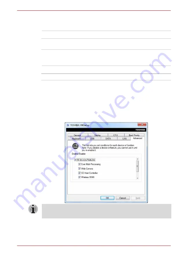
Advanced

Enable/Disable

This tab allows you to set the conditions for each device or function. You 
can enable or disable the selected device or function for power 
management. Disabled mode consumes less power.The setup window will 
be displayed as follows. 

Enabled

Enables Wake-up on LAN from shutdown.

Disabled

Disables Wake-up on LAN from shutdown. 
(Default)

Enabled

Enables Built-in LAN functions (Default).

Disabled

Disables Built-in LAN functions.

If you disable a device or function, you must re-enable it before you can 
use it.

Summary of Contents for TECRA R700

Page 1: ...User s Manual PORTÉGÉ TECRA R700 Series ...

Page 2: ...ormation is only for Turkey x Optical disc drive safety instructions x Precautions xiii Preface Conventions xiv General Precautions Provide adequate ventilation xvi Creating a computer friendly environment xvi Stress injury xvii Heat injury xvii Pressure or impact damage xvii ExpressCard overheating xvii Mobile phones xvii Instruction Manual for Safety and Comfort xviii Chapter 1 Getting Started E...

Page 3: ...he Fingerprint Sensor 4 2 Web Camera 4 8 Using the TOSHIBA Face Recognition 4 9 Using optical disc drives 4 13 Writing CD DVDs 4 17 TOSHIBA DVD PLAYER 4 25 Media care 4 27 Sound System 4 28 Wireless communications 4 31 LAN 4 34 Computer Handling 4 36 Using the Hard Disk Drive HDD Protection 4 37 Taskbar icon 4 37 TOSHIBA HDD Protection Properties 4 37 Details 4 38 Using the TOSHIBA Sleep Utility 4...

Page 4: ...Advanced 7 6 Chapter 8 Troubleshooting Problem solving process 8 1 Hardware and system checklist 8 3 TOSHIBA support 8 20 Appendix A Specifications Physical Dimensions A 1 Environmental Requirements A 1 Power Requirements A 1 Appendix B Display Controller and Video mode Display controller B 1 Video mode B 1 Appendix C Wireless LAN Card Specifications C 1 Radio Characteristics C 1 Supported Frequen...

Page 5: ...Starting the TOSHIBA PC Health Monitor F 1 If a TOSHIBA PC Health Monitor message is displayed F 2 Appendix G Legal Footnotes Non applicable Icons G 1 CPU G 1 Memory Main System G 2 Battery Life G 2 Hard Disk Drive HDD Capacity G 3 LCD G 3 Graphics Processor Unit GPU G 3 Wireless LAN G 3 USB Sleep and Charge G 3 Copy Protection G 4 Glossary Index ...

Page 6: ...validated and reviewed for accuracy The instructions and descriptions it contains are accurate for the TOSHIBA PORTÉGÉ TECRA R700 Series Portable Personal Computer at the time of this manual s production However succeeding computers and manuals are subject to change without notice TOSHIBA assumes no liability for damages incurred directly or indirectly from errors omissions or discrepancies betwee...

Page 7: ...onnect the equipment into an outlet on a circuit different from that to which the receiver is connected Consult the dealer or an experienced radio TV technician for help FCC conditions This device complies with part 15 of the FCC Rules Operation is subject to the following two conditions 1 This device may not cause harmful interference 2 This device must accept any interference received including ...

Page 8: ... Compatibility and safety standards However TOSHIBA cannot guarantee that this product still observes these EMC standards if options or cables not produced by TOSHIBA are connected or implemented In this case the persons who have connected implemented those options cables have to provide assurance that the system PC plus options cables still fulfils the required standards To avoid general EMC prob...

Page 9: ... of this product Furthermore for general safety reasons the use of this product in environments with explosive atmospheres is not permitted VCCI Class B Information Canadian regulatory information Canada only This digital apparatus does not exceed the Class B limits for radio noise emissions from digital apparatus as set out in the Radio Interference Regulation of the Canadian Department of Commun...

Page 10: ...ters toshiba europe com or contact your local city office or the shop where you purchased the product The crossed out wheeled dust bin symbol indicates that batteries and or accumulators must be collected and disposed of separately from household waste If the battery or accumulator contains more than the specified values of lead Pb mercury Hg and or cadmium Cd defined in the Battery Directive 2006...

Page 11: ...stomers with information about the chemical substances in our products according to REACH regulation Please consult the following website www toshiba europe com computers info reach for information about the presence in our articles of substances included on the candidate list according to article 59 1 of Regulation EC No 1907 2006 REACH in a concentration above 0 1 weight by weight Following info...

Page 12: ...ase read this instruction manual carefully and retain for future reference Should the unit ever require maintenance contact an authorized service location Use of controls adjustments or the performance of procedures other than those specified may result in hazardous radiation exposure To prevent direct exposure to the laser beam do not try to open the enclosure Location of the required label on th...

Page 13: ...User s Manual xii PORTÉGÉ TECRA R700 Series DVD Super Multi UJ 844 ...

Page 14: ...sified as a CLASS 1 LASER PRODUCT To use this model properly read the instruction manual carefully and keep this manual for your future reference In case of any trouble with this model please contact your nearest AUTHORIZED service station To prevent direct exposure to the laser beam do not try to open the enclosure ...

Page 15: ...o learn how this manual is organized then become acquainted with this manual by browsing through its pages Be sure to read the Special features section in chapter 3 Hardware Utilities and Options to learn about features that are uncommon or unique to this computer as well as the section on chapter 7 HW Setup to understand how to setup and configure these features Read chapter 3 Hardware Utilities ...

Page 16: ...s name or the text you are to type in is represented in the typeface you see to the left S ABC Names of windows or icons or text generated by the computer that appear on its display screen are presented in the type face you see to the left Indicates a potentially hazardous situation which could result in death or serious injury if you do not follow instructions Pay attention A caution informs you ...

Page 17: ...block the air vents including those located at the base of the computer Always operate your computer on a hard flat surface Using your computer on a carpet or other soft material can block the vents Always provide sufficient space around the computer Overheating your computer or AC adaptor could cause system failure computer or AC adaptor damage or a fire possibly resulting in serious injury Creat...

Page 18: ...direct contact with the metal plate supporting the various interface ports as this can become hot The surface of the AC adaptor can become hot when in use but this condition does not indicate a malfunction If you need to transport the AC adaptor you should disconnect it and let it cool before moving it Do not lay the AC adaptor on a material that is sensitive to heat as the material could become d...

Page 19: ...and a mobile phone that is in use Instruction Manual for Safety and Comfort All important information on the safe and proper use of this computer is described in the enclosed Instruction Manual for Safety and Comfort Be sure to read it before using the computer ...

Page 20: ... and power cord 2 pin plug or 3 pin plug Battery pack Is pre installed in some computer Documentation PORTÉGÉ TECRA R700 Series User Information Guide Instruction Manual for Safety and Comfort If any of the items are missing or damaged contact your dealer immediately Software The following Windows operating system and utility software are pre installed Windows 7 TOSHIBA Value Added Package TOSHIBA...

Page 21: ...n to start using your computer It covers the following topics Connecting the AC adaptor Opening the display Turning on the power Starting up for the first time Turning off the power Restarting the computer System Recovery Options You may not have all the softwares listed above depending on the model you purchased All users should be sure to read the section Starting up for the first time Be sure t...

Page 22: ...evice or application save any data in memory to the hard disk drive or other storage media Failure to do so may result in the loss of data Always use the TOSHIBA AC adaptor that was included with your computer or use AC adaptors specified by TOSHIBA to avoid any risk of fire or other damage to the computer Use of an incompatible AC adaptor could cause fire or damage to the computer possibly result...

Page 23: ...se the adaptor DC output plug could hold an electrical charge and cause an electrical shock or minor bodily injury when touched As a general safety precaution avoid touching any metal parts Never place your computer or AC adaptor on a wooden surface furniture or any other surface that could be marred by exposure to heat since the computer base and AC adaptor s surface increase in temperature durin...

Page 24: ...ide range of angles for optimal viewing While holding down the palm rest with one hand so that the main body of the computer is not raised slowly lift the display panel this will allow the angle of the display panel to be adjusted to provide optimum clarity Figure 1 4 Opening the display panel 1 DC IN 19V jack 2 DC output plug 2 1 1 Display panel 1 Use reasonable care when opening and closing the ...

Page 25: ...ause damage Do not press or push on the display panel Do not lift the computer by the display panel Do not close the display panel with pens or any other objects left in between the display panel and the keyboard When opening or closing the display panel place one hand on the palm rest to hold the computer in place and use the other hand to slowly open or close the display panel Do not use excessi...

Page 26: ... Shut Down Mode no data will be saved and the computer will boot to the operating system s main screen the next time it is turned on 1 If you have entered data either save it to the hard disk drive or to other storage media 2 Make sure all disk disc activity has stopped before removing the CD DVD or floppy diskette 1 Power button 1 When it is displayed be sure to read the Software License Terms ca...

Page 27: ...er recording function Failure to completely shut down the computer in this way could allow the operating system to reactivate and run pre programmed tasks or preserve unsaved data which could interfere with aviation or other systems possibly causing serious injury Before entering Sleep Mode be sure to save your data Do not install or remove a memory module while the computer is in Sleep Mode The c...

Page 28: ... When you turn the power back on you can continue where you left when you shut down the computer Sleep Mode limitations Sleep Mode will not function under the following conditions Power is turned back on immediately after shutting down Memory circuits are exposed to static electricity or electrical noise Hibernation Mode The Hibernation Mode feature saves the contents of memory to the hard disk dr...

Page 29: ...de The computer can be configured to enter Hibernation Mode automatically when you press the power button or close the lid In order to define these settings you can follow the steps as described below 1 Click Start and click the Control Panel 2 Click System and Security and click Power Options 3 Click Choose what the power button does or Choose what closing the lid does 4 Enable the desired Hibern...

Page 30: ...splay the menu window then select Restart from the Shut down options Press the power button and hold it down for five seconds Once the computer has turned itself off wait between ten and fifteen seconds before turning the power on again by pressing the power button System Recovery Options There is a hidden partition allocated on the hard disk drive for the System Recovery Options This partition st...

Page 31: ...your system including the system image backup feature Be sure to connect the AC adaptor when you create Recovery Media Be sure to close all other software programs except the Recovery Media Creator Do not run software such as screen savers which can put a heavy load on the CPU Operate the computer at full power Do not use power saving features Do not write to the media when the virus check softwar...

Page 32: ...ficient capacity of USB Flash Memory before you proceed with the Recovery Media process And then click the Create button Restoring the pre installed software from the Recovery hard disk drive A portion of the total hard disk drive space is configured as a hidden recovery partition This partition stores files which can be used to restore pre installed software in the event of a problem If you subse...

Page 33: ...u can not use System Recovery Options if restoring the pre installed software without System Recovery Options When you reinstall the Windows operating system the hard disk will be reformatted and all data will be lost A recovery DVD or USB Flash Momery created according to the Creating Recovery Media section in this chapter is required to restore the software In order to create a recovery DVD an e...

Page 34: ...ia Please refer to the Boot Priority section in chapter 7 HW Setup for further information 4 A menu will be displayed from which you should follow the on screen instructions When drivers utilities are installed you can setup the respective drivers utilities from the following place To open the setup files Click Start All Programs TOSHIBA Applications and Drivers ...

Page 35: ...e computer with display panel closed Product appearance depends on the model you purchased Left side The following figure shows the computer s left side Legal Footnote Non applicable Icons For more information regarding Non applicable Icons please refer to the Legal Footnotes section in appendix G Please handle your computer carefully to avoid scratching or damaging the surface 1 System indicators...

Page 36: ... objects such as screws staples and paper clips out of the cooling vents Foreign metal objects can create a short circuit which can cause damage and fire possibly resulting in serious injury External monitor port This port provides 15 pin analog VGA port This port allows you to connect an external monitor to the computer There are no fastening screws for an external monitor cable on this computer ...

Page 37: ...Universal Serial Bus Port Foreign metal objects can create a short circuit which can cause damage and fire possibly resulting in serious injury Please note that it is not possible to confirm the operation of all functions of all USB devices that are available In view of this it may be noted that some functions associated with a specific device might not operate properly HDMI out port HDMI out port...

Page 38: ...e jack 9 PC Card slot 5 Universal Serial Bus USB 2 0 port 10 PC Card eject button 2 1 5 5 3 6 9 10 4 7 Bridge media slot This slot lets you insert an SD SDHC SDXC memory card miniSD microSD Card and MultiMediaCard Refer to the Optional devices section in chapter 3 Hardware Utilities and Options Keep foreign metal objects such as screws staples and paper clips out of the Bridge media slot Foreign m...

Page 39: ...s per second 1000BASE T Refer to chapter 4 Operating Basics for details Do not connect any cable other than a LAN cable to the LAN jack It could cause damage or malfunction Do not connect the LAN cable to a power supply It could cause damage or malfunction Security lock slot A security cable can be attached to this slot and then connected to a desk or other large object in order to deter theft of ...

Page 40: ...r to avoid causing any damage Keep foreign metal objects such as screws staples and paper clips out of the PC Card slot Foreign metal objects can create a short circuit which can cause damage and fire possibly resulting in serious injury 1 Battery pack 1 Battery pack The battery pack provides power to the computer when the AC adaptor is not connected For more detailed information on the use and op...

Page 41: ...battery pack ready for removal Docking port This port enables connection of an optional TOSHIBA Hi Speed Port Replicator described in chapter 3 Hardware Utilities and Options Some models are equipped with a Docking port Only the TOSHIBA Hi Speed Port Replicator can be used with this docking port Keep foreign objects out of the docking port A pin or similar object can damage the computer s circuitr...

Page 42: ...re detailed information on removing the battery pack please refer to chapter 6 Power and Power Up Modes Memory module slot The memory module slot allows for the installation replacement and removal of additional memory module Refer to the Additional memory module section in chapter 3 Hardware Utilities and Options 1 Display screen 10 Touch Pad ON OFF button 2 Web Camera 11 Fingerprint Sensor 3 Web...

Page 43: ...ssenger TOSHIBA Web Camera Application will help you to add various video effects to your video or photograph Enables the transmission of video and use of video chat via the internet using specialized applications Some models are equipped with a Web Camera Please refer to the Web Camera section in chapter 4 Operating Basics Web Camera LED The Web Camera LED glows when the Web Camera is operating W...

Page 44: ...or detailed information on Fingerprint Sensor refer to chapter 4 Using the Fingerprint Sensor Some models are equipped with a Fingerprint Sensor Keyboard The internal keyboard provides the embedded numeric overlay keys dedicated cursor control overlay keys Windows Start key and application key Refer to chapter 5 The Keyboard for details Power button Press this button to turn the computer s power o...

Page 45: ... green when power is being correctly supplied from the AC power adaptor However If the output voltage from the adaptor is abnormal or if the computer s power supply malfunctions this indicator will flash orange Power The Power indicator normally glows green when the computer is turned on However if you turn the computer off into Sleep Mode this indicator will flash orange approximately two second ...

Page 46: ...TA The Hard Disk Drive Optical Disc Drive eSATA indicator glows green whenever the computer is accessing the built in hard disk drive optical disc drive or eSATA device Bridge media slot The Bridge media slot indicator glows green when the computer is accessing the Bridge media slot Wireless communication The Wireless communication indicator blinks orange when the Bluetooth and Wireless LAN functi...

Page 47: ...erating Basics Region codes for DVD drives and media DVD Super Multi drives and their associated media are manufactured according to the specifications of six marketing regions When you purchase DVD Video make sure it matches your drive otherwise it will not play properly 1 CAPS LOCK indicator 1 CAPS LOCK This indicator glows green when letter keys are locked into their uppercase format Code Regio...

Page 48: ...ce The recorded data cannot be erased or changed DVD RW DVD RW and DVD RAM discs can be recorded more than once Formats The drive supports the following formats DVD Super Multi drive The drive supports the formats CD ROM DVD ROM DVD Video CD DA CD Text Photo CDTM single multi session CD ROM Mode 1 Mode 2 CD ROM XA Mode 2 Form1 Form2 Enhanced CD CD EXTRA Addressing Method 2 CD R CD RW DVD R DVD RW ...

Page 49: ...ut using an adaptor DVD read 8 speed maximum DVD R write 8 speed maximum DVD RW write 4 speed maximum DVD R write 8 speed maximum DVD RW write 4 speed maximum DVD RAM write 3 speed maximum CD read 24 speed maximum CD R write 16 speed maximum CD RW write 10 speed maximum Ultra speed media The read speed is slower at the center of a disc and faster at the outer edge DVD read 8 speed maximum DVD R wr...

Page 50: ...omputer Please refer to chapter 6 Power and Power up Modes for further information Figure 2 11 The AC adaptor 2 pin plug Figure 2 12 The AC adaptor 3 pin plug Depending on the model in question either a 2 pin or 3 pin adaptor power lead will be bundled with the computer Do not use a 3 pin to 2 pin conversion plug The supplied power cord conforms to safety rules and regulations in the region the pr...

Page 51: ...r computer or use AC adaptors specified by TOSHIBA to avoid any risk of fire or other damage to the computer Use of an incompatible AC adaptor could cause fire or damage to the computer possibly resulting in serious injury TOSHIBA assumes no liability for any damage caused by use of an incompatible adaptor ...

Page 52: ...he model you purchased Processor CPU Your computer is equipped with one processor and processor type varies depending on model To check which type of processor is included in your model open the TOSHIBA PC Diagnostic Tool Utility by clicking Start All Programs TOSHIBA Utilities PC Diagnostic Tool Legal Footnote CPU For more information on the CPU please refer to the Legal Footnotes section in appe...

Page 53: ...ory might be displayed as approximately 3 GB only depending on the computer s hardware specifications This is correct because the operating system usually displays the available memory instead of the physical memory RAM built into the computer Various system components like the video adapter s GPU and PCI devices like Wireless LAN etc require their own memory space Since a 32 bit operating system ...

Page 54: ... As the AC adaptor is universal it can receive a range of AC voltages from 100 to 240 volts however you should note that the output current varies among different models Using the wrong adaptor can damage your computer Refer to the AC adaptor section in chapter 2 The Grand Tour Hard disk drive or Solid state drive This computer is equipped with one of the following hard disk drive HDD types The ca...

Page 55: ...l the word HDD or Hard disk drive also refers to the SSD unless otherwise stated SSD is a large capacity storage media which uses Solid State Memory in place of a magnetic disk of the hard disk Under certain unusual conditions of prolonged non use and or exposure to high temperatures the SSD may be vulnerable to data retention errors Legal Footnote Hard Disk Drive HDD Capacity For more information...

Page 56: ...s Maximum Quality or disable this feature Please visit your region s web site or refer to the catalog for the configuration details of the model that you have purchased Sound Legal Footnote LCD For more information regarding the LCD please refer to the Legal Footnotes section in appendix G Graphics controller The graphics controller maximizes display performance Refer to Display Controller and Vid...

Page 57: ...ASE T Fast Ethernet LAN 100 megabits per second 100BASE TX and Gigabit Ethernet LAN 1000 megabits per second 1000BASE T Bluetooth Some computers in this series have Bluetooth wireless communication function which eliminates the need for cables between electronic devices such as computers printers and mobile phones When it is enabled Bluetooth provides the wireless personal area network environment...

Page 58: ... not accessed for a specified time with power being restored when the hard disk drive is next accessed This can be specified in the Power Options System automatic Sleep Hibernation Mode 1 This feature automatically shuts down the system into either Sleep Mode or Hibernation Mode when there is no input or hardware access for a specified time This can be specified in the Power Options Keypad overlay...

Page 59: ...erature sensor so that if the computer s internal temperature rises to a certain level the cooling fan is turned on or the processing speed is lowered This can be specified in the Power Options TOSHIBA HDD Protection This feature uses the acceleration sensor built in the computer to detect vibration and shocks and automatically moves the hard disk drive s read write head to a safe position in orde...

Page 60: ...USB port when your computer is in Sleep Mode Hibernation Mode or in the shutdown state This function is worked by the Sleep Utility For more information please refer to the Using the TOSHIBA Sleep Utility section in chapter 4 Operating Basics Legal Footnote Sleep and Charge For more information regarding Sleep and Charge please refer to the Legal Footnotes section in Appendix G USB Wakeup function...

Page 61: ...A Power Saver provides you with the features of more various power supply managements TOSHIBA Button Support This utility controls the following computer button functions Eco button TOSHIBA Presentation button The starting application from the button can be changed TOSHIBA Zooming Utility This utility allows you to enlarge or reduce the icon size on the Windows Desktop or the zoom factor associate...

Page 62: ...n order to access its specific function When set the FN key will remain active until another key is pressed Fingerprint Utility This product has a fingerprint utility installed for the purpose of enrolling and recognizing fingerprints which can then be linked to a username and password in order to remove the need to input these details from the keyboard Just by swiping an enrolled finger against t...

Page 63: ...functions Click Start All Programs TOSHIBA DVD PLAYER TOSHIBA DVD PLAYER Refer to the TOSHIBA DVD PLAYER section in Chapter 4 Operating Basics for more details Frame dropping audio skipping or out of synch audio and video may occur during playback of some DVD Video titles Make sure to connect the computer s AC adaptor when playing a DVD Video Power saving features may interfere with smooth playbac...

Page 64: ...d System section in chapter 4 Operating Basics TOSHIBA eco Utility Your computer is equipped with eco mode This mode slightly lowers performance of some devices to reduce electric power consumption You can realize measurable power savings by using it continuously TOSHIBA eco Utility helps you monitor your power savings by showing approximate real time power consumption Furthermore it shows approxi...

Page 65: ... CD DVDs which can store copies of the files and folders on your computer s hard disk drive This software can be used on models with a optical disc drive To access this utility click Start All Programs TOSHIBA CD DVD Applications Disc Creator TOSHIBA DVD RAM Utility This utility has the function of Physical Format and Write Protect to DVD RAM This utility is contained the setup module of TOSHIBA D...

Page 66: ...oller This application allows you to control your music pictures and videos by streaming content to any compatible device in your home To access this utility click Start All Programs TOSHIBA TOSHIBA Media Controller TOSHIBA Media Controller For more information please refer to the TOSHIBA Media Controller Help TOSHIBA Speech System The TOSHIBA Speech System consists of a voice composition applicat...

Page 67: ...that can accommodate a Type II format card Any PC Card that meets industry standards either manufactured by TOSHIBA or another vendor can be installed as the slot supports 16 bit PC Cards and 32 bit CardBus cards For reference CardBus supports the newer standard of 32 bit PC Cards and provides superior performance for the greater demands of applications such as multimedia data transmission 1 Turn ...

Page 68: ...Insert the PC Card into the PC Card slot on the right side of the computer 4 Press the PC Card gently to ensure a firm connection is made Figure 3 1 Inserting the PC Card PC Cards can sometimes become hot during computer operation Before you remove a PC Card always wait for it to cool You could get burned removing a hot PC Card Some models are equipped with either a PC Card slot or a ExpressCard s...

Page 69: ...ard into the PC Card slot ExpressCard Some models are equipped with a single ExpressCard slot into which any ExpressCard device that meets industry standards either manufactured by TOSHIBA or another vendor can be installed The slot supports hot plug connection and utilizes the PCI Express interface that supports the reading and writing of data at a theoretical maximum rate of 2 5Gbps Inserting an...

Page 70: ...serting the ExpressCard you should refer to its documentation and also check the configuration in Windows in order to ensure that it is correct Removing an ExpressCard To remove an ExpressCard follow the steps as detailed below 1 Open the Safely Remove Hardware and Eject Media icon on the Windows Taskbar 2 Point to ExpressCard and click the left Touch Pad control button 3 Press the ExpressCard in ...

Page 71: ...idge media slot Never allow metal objects such as screws staples and paper clips to enter the computer or Keyboard Foreign metal objects can create a short circuit which can cause computer damage and fire possibly resulting in serious injury Memory Stick Duo is not compatible with the Bridge media slot Do not insert Memory Stick Duo into the slot or you may not be able to remove it Data may be los...

Page 72: ...cards from SDHC and SDXC memory cards SD SDHC and SDXC memory cards appear the same externally However the logo on SD SDHC and SDXC memory cards is different so pay careful attention to the logo when purchasing The maximum capacity of SD memory cards is 2GB The maximum capacity of SDHC memory cards is 32GB The maximum capacity of SDXC memory cards is 64GB Please note that not all memory media have...

Page 73: ...edia close to containers of liquid Do not touch the metal part of a card or expose it to liquids or let it get dirty After using card return it to its case The card is designed so that it can be inserted only one way Do not try to force the card into the slot Do not leave a card partially inserted in the slot Press the card until you hear it click into place Memory card care Set the write protect ...

Page 74: ...ot on the right side of the computer 3 Press the memory media gently to ensure a firm connection is made Figure 3 6 Inserting a memory media Set the write protect switch to the lock position if you do not want to record data 1 Bridge media slot 2 Memory media 2 1 Make sure memory media is oriented properly before you insert it If you insert the media in wrong direction you may not be able to remov...

Page 75: ...install additional memory into the computer in order to increase the amount of system memory that is available This section describes how to install and remove optional memory modules 1 Bridge media slot 1 Make sure the Bridge Media slot indicator is out before you remove the memory media or turn off the computer s power If you remove the memory media or turn off the power while the computer is ac...

Page 76: ...uter will operate in dual channel mode You can access the inserted memory modules efficiently in dual channel Use only memory modules approved by TOSHIBA Do not try to install or remove a memory module under the following conditions The computer is turned on The computer was shut down in either Sleep or Hibernation Mode Wake up on LAN is enabled The wireless communication functionalities are turne...

Page 77: ...t the screws are attached to the cover in order to prevent them from being lost 6 Slide your fingernail or a thin object under the cover and lift it off Figure 3 8 Removing the memory module cover 7 Align the notch of the memory module with that of the memory slot and gently insert the module into the slot at about a 30 degree angle before holding it down until the latches on either side snap into...

Page 78: ...erious injury Do not touch the connectors on the memory module or on the computer Debris on the connectors may cause memory access problems Align the grooves along the edges of the memory module with the locking tabs on the connector and insert the module into the connector firmly if you find it difficult to install the memory module gently prise the locking tabs outwards using the tip of your fin...

Page 79: ...omputer 3 Close the display panel 4 Turn the computer upside down and remove the battery pack refer to Replacing the battery pack section in chapter 6 Power and Power Up Modes if required 5 Loosen the screws securing the memory module cover in place please note that the screws are attached to the cover in order to prevent them from being lost 6 Slide your fingernail or a thin object under the cove...

Page 80: ...analog monitor can be connected to the external monitor port on the computer To connect a monitor follow the steps as detailed below Do not touch the connectors on the memory module or on the computer Debris on the connectors may cause memory access problems 1 Latches 1 1 Take care to ensure that the memory module cover is firmly closed There are no fastening screws for an external monitor cable o...

Page 81: ...ou turn the computer s power off be sure to press FN F5 hot key again to switch to the internal display Please refer to chapter 5 The Keyboard for further details on using hot keys to change the display setting When displaying desktop at external analog monitor desktop is sometimes displayed on the center of the monitor with black bars around desktop with small size At that time please read the ma...

Page 82: ...y to force the connection doing so can damage the connecting pins 1 eSATA USB combo port 2 eSATA cable 1 2 A connected eSATA device may not be recognized if it is connected to the computer s eSATA USB combo port while the computer is in Sleep Mode or Hibernation Mode If this occurs disconnect the eSATA device and then reconnect the device while the computer is turned on If you connect an eSATA dev...

Page 83: ...ing the HDMI out port 1 Plug one end of the HDMI cable into the HDMI port of the HDMI device 2 Plug the other end of the HDMI cable into the HDMI out port on your computer Figure 3 14 Connecting the HDMI out port As the port operation of all HDMI High Definition Multimedia Interface monitors have not been confirmed some HDMI monitors may not function properly 1 HDMI out port 2 HDMI cable 1 2 When ...

Page 84: ... plug it in please wait at least 5 seconds before you replug the HDMI cable again When you connect a television or external monitor to the HDMI port and you connect the television external monitor or external sound device to another port When you change the display output or Unplug re plug the HDMI cable The sound output device and the display output device maybe changed automatically by the syste...

Page 85: ...olor 32bit 50Herts 576p 720 by 480 True Color 32bit 60Herts 480p Display mode at List All Modes HD Format The above display mode is a typical HDMI display mode The selectable display modes will vary for different HDMI monitors You must connect the AC adaptor before you connect to a TOSHIBA Hi Speed Port Replicator When a TOSHIBA Hi Speed Port Replicator is connected to the computer you can not use...

Page 86: ...roduct Please refer to the instructions for the product you are using for more information Connecting the security lock In order to connect a security cable to the computer follow the steps as detailed below 1 Turn the computer so its right side faces you 2 Align the security cable with the lock slot and secure it in place Figure 3 15 Security lock Optional accessories You are able to add a number...

Page 87: ...be purchased for use as either a spare or replacement Please refer to chapter 6 Power and Power up Modes for further information TOSHIBA Hi Speed Port Replicator The TOSHIBA Hi Speed Port Replicator provides the ports available on the computer in addition to a RJ45 LAN jack an External monitor port a DC IN 19V jack a Security lock slot four Universal Serial Bus 2 0 ports two Universal Serial Bus 3...

Page 88: ...u want the on screen pointer to go Figure 4 1 Touch Pad and Touch Pad control buttons Press Touch Pad ON OFF button could enable or disable the Touch Pad function The two buttons below the Touch Pad are used like the buttons on a standard mouse press the left button to select a menu item or to 1 Touch Pad ON OFF button 4 Fingerprint Sensor 2 Touch Pad 5 Touch Pad control buttons lef t 3 Touch Pad ...

Page 89: ...e the password protected screen saver when returning from a power saving mode such as Sleep Mode Authentication of the User Password and if applicable the HDD Hard Disk Drive Password when booting up the computer boot authentication Single Sign On feature How to Swipe your Finger Using the following steps when swiping fingers for fingerprint registration or authentication will help to minimize aut...

Page 90: ...rt may scratch it Do not paste stickers or write on the sensor Do not touch the sensor with a finger or any other object which may have a build up of static electricity on it Observe the following before you place your finger on the sensor whether for fingerprint enrollment registration or recognition Wash and dry your hands thoroughly 1 Sensor 1 1 Avoid swiping with your finger stiff or pressed t...

Page 91: ...recognition success rate Also if the fingerprint is worn down or the finger becomes thinner or fatter the recognition success rate may be lowered As the fingerprint for each finger is different and unique you should ensure that only the registered or enrolled fingerprint or fingerprints are used for identification Check the position and speed at which you swipe your finger across the sensor please...

Page 92: ...creen is displayed Confirm the message and then click Next 5 The scanning practice screen is displayed You are able to practice swiping three times your finger to ensure you use the correct method When you have finished practicing swiping your finger click Next 6 Swipe three times with the same finger If scanning of fingerprint succeeds Enrollment succeed Do you want to save this fingerprint messa...

Page 93: ...gerprint is registered the message Sorry At least one fingerprint is required will appear after clicking OK You are not allowed to delete a unique fingerprint 5 Click Close 6 Are you sure you want to quit is displayed Click OK It will be returned to the TOSHIBA Fingerprint Utility main menu Delete all users fingerprints 1 In the TOSHIBA Fingerprint Utility main menu click Run as administrator in t...

Page 94: ...lease logon using the Windows logon password Please logon using the Windows logon password if the fingerprint authentication failed for five times To logon using the Windows logon password enter the Windows logon password at the Welcome screen as normal A warning message will be displayed when authentication is abnormal or authentication is not successful within a fixed duration You must ensure th...

Page 95: ...at your fingerprint is enrolled before configuring the settings 1 Logon as Administrator means a user has administrator privileges 2 Click Start All Programs TOSIHBA Utilities TOSHIBA Fingerprint Utility 3 Swipe your finger across the fingerprint sensor 4 The TOSHIBA Fingerprint Utility main menu is displayed Click Run As Administrator in lower left 5 User Account Control window is displayed Click...

Page 96: ...Web Camera Using the TOSHIBA Face Recognition Some models are preinstalled with a TOSHIBA Face Recognition TOSHIBA Face Recognition uses a face verification library to verify the face data of users when they log in to Windows The user can thus avoid 1 Web Camera 2 Web Camera LED 2 1 Do not point the web camera directly at the sun Do not touch or press strongly on the web camera lens Doing so may r...

Page 97: ... TOSHIBA Face Recognition does not guarantee the correct identification of a user Changes to the likeness of a registrant such as hair style changes wearing a cap or wearing glasses may effect the recognition rates when such changes occur after the registrant had registered TOSHIBA Face Recognition may incorrectly recognize faces that are similar to a registrant For high security purposes TOSHIBA ...

Page 98: ... fits within the face shaped frame 5 Once your face has been positioned properly the recording will commence Start moving your neck very slightly to the left and right and then move your neck down and up 6 Registration will end after you have repeatedly moved your neck left right down and up When the register succeeds below message will be displayed on the screen Registration successful Now we ll ...

Page 99: ...ow to login to Windows with TOSHIBA Face Recognition Two authentication modes are provided 1 N Mode Login screen If the face authentication tile is selected by default you can log in without using the keyboard or mouse 1 1 Mode Login screen This mode is essentially the same as AUTO mode but the Select Account screen will appear before the Display Captured Image screen and you will need to select t...

Page 100: ... equipped with an optical disc drive The full size drive provides high performance execution of CD DVD ROM based programs You can run either 12 cm 4 72 or 8 cm 3 15 CD DVDs without an adaptor When the computer is accessing a DVD Super Multi drive an indicator on the drive glows If you have a DVD Super Multi drive please also refer to the Writing CD DVDs section for precautions on writing to CDs DV...

Page 101: ...2 Eject button 1 Laser lens 1 2 1 When the disc tray is fully opened the edge of the computer will extend slightly over the CD DVD tray Therefore you will need to turn the CD DVD at an angle when you place it in the disc tray After seating the CD DVD however make sure it lies flat Gently support the disc tray from below with your free hand when inserting or removing CD DVDs from the optical disc d...

Page 102: ...could cause misalignment Prevent foreign objects from entering the drive Check the surface of the disc tray especially the area behind the front edge of the disc tray to make sure there are no such objects before closing the drive If the CD DVD is not seated properly when the disc tray is closed the CD DVD might be damaged Also the disc tray might not open fully when you press the eject button Do ...

Page 103: ... Removing a CD DVD DVD Supter Multi drive models 3 Push the center of the disc tray to close it Press gently until it locks into place How to remove CD DVD when the disc tray will not open Pressing the eject button will not open the disc tray when the computer power is off If the power is off you can open the disc tray by inserting a slender object about 15 mm such as a straightened paper clip int...

Page 104: ...u use the eject hole If the CD DVD is spinning when you open the disc tray the CD DVD could fly off the spindle and cause injury Please refer to the Writable discs chapter 2 for details about the types of writable CD and DVD discs that can be supported by this computer Do not turn off the power to the optical disc drive while the computer is accessing it as this may cause you to lose data To write...

Page 105: ...r loss of the recorded contents Damage that may be caused by using third party equipment or software Given the technological limitations of current optical disc writing drives you may experience unexpected writing or rewriting errors due to disc quality or problems with hardware devices In view of this it is good practice to make two or more copies of important data in case of any undesired change...

Page 106: ...DVD Specifications for Recordable Disc for General Version 2 0 MITSUBISHI KAGAKU MEDIA CO LTD for 8x and 16x speed media Panasonic Co Ltd for 4x and 16x speed media TAIYO YUDEN Co Ltd for 4x 8x and 16x speed media Hitachi Maxell Ltd for 8x speed media DVD R MITSUBISHI KAGAKU MEDIA CO LTD for 8x and 16x speed media DVD RW DVD Specifications for Recordable Disc for Version 1 1 or version 1 2 Victor ...

Page 107: ... to connect the AC adaptor to the computer before you write or rewrite any information Before you enter either Sleep Mode or Hibernation Mode take care to ensure that any DVD RAM writing has been completed In this instance writing is finished if you can eject the DVD RAM media Be sure to close all other software programs except for the writing software itself Do not run software such as a screen s...

Page 108: ...al Version 2 0 MITSUBISHI KAGAKU MEDIA CO LTD for 8x and 16x speed media TAIYO YUDEN Co Ltd for 8x and 16x speed media Hitachi Maxell Ltd for 8x speed media DVD R DL MITSUBISHI KAGAKU MEDIA CO LTD for 4x and 8x speed media DVD R MITSUBISHI KAGAKU MEDIA CO LTD for 8x and 16x speed media TAIYO YUDEN Co Ltd for 8x and 16x speed media DVD R DL MITSUBISHI KAGAKU MEDIA CO LTD for 4x and 8x speed media D...

Page 109: ...ted you do not delete data from the wrong one In writing to DVD R DVD R DL DVD RW DVD R DVD R DL DVD RW or DVD RAM media some space is required for file management so you may not be able to write to the full capacity of the disc Since the disc is based on the DVD standard it might be filled with dummy data if the written data is less than about 1GB Therefore in these circumstance even if you write...

Page 110: ...ite or rewrite data to optical media Always copy data from the hard disk drive to the optical media do not use the cut and paste function as the original data will be lost if there is a write error Do not perform any of the following actions Change users in the Windows 7 Operating Systems Operate the computer for any other function including such tasks as using a mouse or Touch Pad or closing open...

Page 111: ...g the Disc Backup function of TOSHIBA Disc Creator TOSHIBA Disc Creator cannot record in packet format You might not be able to use the Disc Backup function of TOSHIBA Disc Creator to back up a DVD R DVD R DL DVD RW DVD R DVD R DL or DVD RW disc that was made with other software on a different optical media recorder If you add data to a DVD R DVD R DL DVD R or DVD R DL disc that you have already r...

Page 112: ...HIBA DVD PLAYER Please be aware of the following limitations when you use the TOSHIBA DVD PLAYER Notes on use TOSHIBA DVD PLAYER software is supported for playback of DVD Video and DVD VR Frame dropping audio skipping or out of synch audio and video may occur during playback of some DVD Video titles Close all other applications when using the TOSHIBA DVD PLAYER Do not open any other applications o...

Page 113: ...reen function is disabled when TOSHIBA DVD PLAYER is running Please close the TOSHIBA DVD PLAYER to use the Print Screen function Print Screen functions are disabled even when running other applications besides TOSHIBA DVD PLAYER and when TOSHIBA DVD PLAYER is minimized For some DVD Video discs using the control window to change the audio track will also change the subtitle track Carry out the ins...

Page 114: ... start TOSHIBA DVD PLAYER Operating TOSHIBA DVD PLAYER Notes on Using TOSHIBA DVD PLAYER Screen display and available features may vary amongst DVD Videos and scenes If the menu is opened in the Display Area using the Control window s Top Menu or Menu buttons touch pad and mouse menu operations may not be able to be used Open TOSHIBA DVD PLAYER HELP TOSHIBA DVD PLAYER features and instructions are...

Page 115: ...he speaker icon on the Taskbar and select Open Volume Mixer from the sub menu Adjust speaker volume by moving the slider up or down under Device to raise or lower the volume of your speakers Click the Mute button to mute the volume You may see another control under Applications in Volume Mixer It is the control for an application which is currently running The System Sounds is always displayed sin...

Page 116: ...t input device To change the default device click the Set Default Device button under the chosen device tab Information Click the Information button to view hardware information software information and language setting Power Management The audio controller in your computer can be turned off when the audio function is not used To adjust the configuration of audio power management click the Power M...

Page 117: ...enu of Default Format and then click OK 4 On the Recording tab select Microphone and click Properties 5 On the Advanced tab select 2 channel 16 bit 48000 Hz DVD Quality in the pull down menu of the Default Format pane 6 On the Enhancements tab select the Acoustic Echo Cancellation check box and click Apply Notes on Using Microphone You can use the built in or an external microphone that connects t...

Page 118: ... a microwave oven or in areas subject to radio interference or magnetic fields Interference from a microwave oven or other source can disrupt Wi Fi or Bluetooth operation Turn all wireless functionalities off when near a person who may have a cardiac pacemaker implant or other medical electric device Radio waves may affect pacemaker or medical device operation possibly resulting in serious injury ...

Page 119: ...Bluetooth wireless technology eliminates the need for cables such as desktop computers between your PC and other electronic devices example of printers and mobile phones You cannot use the computer s built in Bluetooth functions and an external Bluetooth adaptor simultaneously For reference Bluetooth wireless technology has the following features Worldwide operation The Bluetooth radio transmitter...

Page 120: ...etooth is not supported in a multi user environment This means that when you use Bluetooth other users that are logged into the same computer will not be able to use this type of functionality Product Support The latest information regarding operating system support language support or available upgrades can be found on our web site http www toshiba europe com computers tnt bluetooth htm in Europe...

Page 121: ...le or higher You cannot use a CAT3 cable If you are using Ethernet LAN 10 megabits per second 10BASE T you can connect with a CAT3 or higher cable Indicator status Indication Indicator off The wireless communication functionalities are off no wireless functionality is available Indicator glows Wireless communication functionalities are on Except for the stopped device by the software switch all th...

Page 122: ...ct the LAN cable follow the steps as detailed below 1 Pinch the lever on the connector in the computer s LAN jack and pull out the connector 2 Disconnect the cable from the LAN hub or router in the same manner Check with your LAN administrator and hardware or software vendor before disconnecting from the hub Connect the AC adaptor before connecting the LAN cable The AC adaptor must remain connecte...

Page 123: ...en moving it in order to help ensure trouble free operation Before moving the computer it is recommended that you change the setting associated with the Hard Disk Drive Protection feature Please refer to the section Using the Hard Disk Drive HDD Protection in this chapter for further information Make sure all disk disc activity has ended before moving the computer check that the HDD and other indi...

Page 124: ...ll be displayed on the screen and the icon in the Taskbar notification area will change to the protection state This message is displayed until the OK button is pressed or 30 seconds pass When vibration subsides the icon returns to the normal state Taskbar icon TOSHIBA HDD Protection Properties You can change the TOSHIBA HDD Protection settings by using the TOSHIBA HDD Protection Properties window...

Page 125: ...s handheld or mobile usage the detection level automatically switches according to the power connection mode 3D Viewer This feature displays a 3D object on the screen which moves in according to tilting or vibration of the computer When the TOSHIBA HDD Protection detects computer vibration the Hard Disk Drive head is parked and the 3D object disk rotation will stop When the head is un parked the d...

Page 126: ...t with the USB specification In those cases turn the power of the computer ON to charge the device This function does not work when the computer is booting in Sleep Mode in Hibernation Mode in transition to Hibernation Mode recovering from Hibernation Mode or powered off Do not subject the computer to vibration or impact while the function is disabled When USB Sleep and Charge function is enabled ...

Page 127: ...and stop using this function 1 Some computers may not support all modes Battery Settings This utility can be used to specify the lower limit of remaining battery life for USB Sleep and Charge Move the slider bar to specify the lower limit If the remaining battery life falls below the setting the USB Sleep and Charge function will be stopped Clearing the Enable under Battery Mode check box sets the...

Page 128: ... on the fan first then if necessary lowering the processor speed or by lowering the processor speed first then if necessary turning on the fan Both of these functions are controlled through the Power Options When the processor s temperature falls within normal range the fan will be turned off and the processor operation returned to its standard speed If the processor s temperature reaches an unacc...

Page 129: ...ctuation marks and special symbols that appear on the screen However there are some differences between using a typewriter and using a computer keyboard Letters and numbers produced in computer text vary in width Spaces which are created by a space character may also vary depending on line justification and other factors The lowercase l el and the number 1 one together with the uppercase O oh and ...

Page 130: ... FN function is unique to TOSHIBA computers and is used in combination with other keys to form soft keys Soft keys are key combinations that enable disable or configure specific features Emulating keys on an enhanced keyboard Figure 5 1 A 104 key enhanced keyboard layout This computer s keyboard is designed to provide all the features of the 104 key enhanced keyboard Since the keyboard is smaller ...

Page 131: ...efault is off Hot keys Hot keys pressing FN a function or ESC key let you enable or disable certain features of the computer Mute Pressing FN ESC turns the volume on and off Lock Pressing FN F1 enters Lock computer mode To restore your desktop you need to log on again Power Plan Pressing FN F2 changes the power settings Sleep Pressing FN F3 switches the system to Sleep Mode Hibernate Pressing FN F...

Page 132: ...ay TOSHIBA Zooming Utility reduce Pressing FN 1 reduces the icon size on the desktop or the font sizes within one of the supported application windows TOSHIBA Zooming Utility enlarge Pressing FN 2 enlarges the icon size on the desktop or the font sizes within one of the supported application windows Volume down Pressing FN 3 decreases the volume in increment Volume up Pressing FN 4 increases the v...

Page 133: ...d but includes a numeric keypad overlay which functions like one this is located in the center of the keyboard with the relevant keys having grey letters at their front edge The overlay provides the same functions as the numeric keypad on a standard 104 105 key enhanced keyboard Turning on the overlays The numeric keypad overlay can be used for numeric data input or cursor and page control Arrow M...

Page 134: ...ng the selected overlay function Temporarily using overlay overlay off While using the normal keyboard function you can temporarily use the keypad overlay without having to turn it on 1 Hold down FN key 2 Release FN key to return to normal keyboard operation Temporarily changing modes If the computer is in Numeric Mode you can switch temporarily to Arrow Mode by pressing a SHIFT key while if it is...

Page 135: ...00 Series ASCII codes 1 Hold down ALT with the overlay on or ALT FN with overlay off 2 Using the overlay keys type the ASCII code of the character you require 3 Release ALT or ALT FN the ASCII character will appear on the display screen ...

Page 136: ...mputer s operating capability and battery charge status are affected by different power conditions including whether an AC adaptor is connected whether a battery pack is installed and what the charge level is for that battery Power on Power off no operation AC adaptor connected Battery fully charged Operates No charge LED Battery green DC IN green No charge LED Battery green DC IN green Battery pa...

Page 137: ... flashes orange DC IN off Battery charge is exhausted Computer shuts down No battery installed No operation LED Battery off DC IN off Power on Power off no operation Flashing orange The battery charge is low the AC adaptor must be connected in order to recharge the battery Orange Indicates the AC adaptor is connected and the battery is charging Green Indicates the AC adaptor is connected and the b...

Page 138: ... the battery pack save your data and shut down the computer or place the computer into Hibernation Mode Please be aware that when placing the computer into Hibernation Mode the contents of memory will be saved to the hard disk drive although for safety sake it is best to also save your data manually Green Indicates the AC adaptor is connected and is correctly supplying power to the computer Flashi...

Page 139: ...the computer is turned off even if the AC adaptor is attached Make sure the battery is securely installed in the computer before attempting to charge the battery pack Improper installation could generate smoke or fire or cause the battery pack to rupture Keep the battery pack out of reach of infants and children It can cause injury The battery pack is lithium ion batteries which can explode if not...

Page 140: ...onditions The battery is extremely hot or cold if the battery is extremely hot it might not charge at all To ensure the battery charges to its full capacity you should charge it at room temperature of between 5 to 35 C 41 to 95 F The battery is nearly completely discharged In this instance you should leave the AC adaptor connected for a few minutes and the battery should begin charging The Battery...

Page 141: ...splay power off period Hard disk drive power off period How often and for how long you use the hard disk drive and external disk c drives for example optical disc and floppy diskette drive How much charge the battery contained to begin with How you use optional devices such as an ExpressCard to which the battery supplies power Whether you enable Sleep Mode which can conserve battery power if you a...

Page 142: ...ator flashes or there is some other warning to indicate a low battery condition go to Step 4 d Connect the AC adaptor to the DC IN 19V jack of the computer and to a wall outlet that is supplying power The DC IN indicator should glow green and the Battery indicator should glow orange to indicate that the battery pack is being charged however in the event that DC IN indicator does not glow this indi...

Page 143: ...sing the battery pack Installing the battery pack To install a battery pack follow the steps as detailed below Do not remove the battery pack while the computer is in Sleep Mode Data is stored in RAM so if the computer loses power it could be lost In Hibernation Mode data will be lost if you remove the battery pack or disconnect the AC adaptor before the save is completed Wait for the Hard Disk Dr...

Page 144: ...alidate user rights when using TOSHIBA Password Utility to delete or change passwords etc User Password field Set button Click this button to register a password of up to 50 characters After a password is set you will be prompted to enter it when you start the computer Check Set the same string simultaneously as the HDD User Password when setting the HDD User Password 1 Battery pack 2 Battery lock...

Page 145: ...sure that the registered password is correct by outputting the character string to the password file When entering a password do not enter any characters for example or produced by pressing the SHIFT or ALT keys and so on To start BIOS Setup 1 Turn on the computer while pressing the F2 key 2 Release the F2 key when the TOSHIBA Leading Innovation screen appears To end the BIOS Setup 3 Press F10 and...

Page 146: ...ike to swipe your finger or cannot authenticate the fingerprint for some reasons push the BACK SPACE key to skip the fingerprint authentication screen You can try to swipe the fingerprint up to five times If you failed fingerprint authentication five times you must enter the password manually to start the computer Enter the password manually To enter a password manually follow the steps as detaile...

Page 147: ...pter 5 The Keyboard for further details Panel power on off You can set up your computer so that power is turned off automatically when you close the display panel and turned on again when you open it Please note that this function is only available for Sleep Mode or Hibernation Mode not for Shut Down Mode System automatic Sleep Hibernation This feature automatically turns off the system in Sleep o...

Page 148: ...t Priority Keyboard USB SATA LAN and Advanced to allow specific functions of the computer to be configured In addition there are also three buttons OK Cancel and Apply General This window displays the BIOS EC version and contains two buttons Default and About Setup This field displays the installed BIOS version date and EC version OK Accepts your changes and closes the HW Setup window Cancel Close...

Page 149: ...e Boot Priority Options setting window will be displayed as shown below Click the The Power On Display is supported with some models Auto Selected Selects an external monitor if one is connected otherwise it selects the internal display default System LCD Only Selects the internal LCD even if an external monitor is connected Dynamically Switchable The processor s power consumption and automatic cl...

Page 150: ...TOSHIBA Leading Innovation screen appears release the F12 key 2 Use the up and down cursor keys to select the boot device you want and press ENTER U Selects the USB floppy diskette drive 1 N Selects the network 1 Selects the built in hard disk drive C Selects the optical disc drive 2 S Selects the USB memory drive E Selects the eSATA HDD If a Supervisor Password has been set manual boot device sel...

Page 151: ...Use this option to enable or disable USB floppy diskette drive legacy emulation If your operating system does not support USB you can still use HDD Sets the USB memory to be the equivalent of a hard disk drive default With this setting the USB memory device can be used to start the computer as though it were a hard disk drive based on the hard disk drive settings within both the Boot Priority and ...

Page 152: ...LAN function The Enabled Enables the USB floppy diskette drive legacy emulation function Default Disabled Disables the USB floppy diskette drive legacy emulation function Enabled Enables the eSATA port Default Disabled Disables the eSATA port in order to save power Performance Let HDD SSD work with maximum performance Default Battery life Let HDD SSD work with battery life mode If this setting is ...

Page 153: ...le This tab allows you to set the conditions for each device or function You can enable or disable the selected device or function for power management Disabled mode consumes less power The setup window will be displayed as follows Enabled Enables Wake up on LAN from shutdown Disabled Disables Wake up on LAN from shutdown Default Enabled Enables Built in LAN functions Default Disabled Disables Bui...

Page 154: ...rint a copy of the screen using the computer s PRTSC key Please also be aware that the questions and procedures described in this chapter are meant only as a guide they are not definitive problem solving techniques In reality many problems can be solved simply but a few may require help from your reseller dealer or service provider if you find you need to consult others be prepared to describe the...

Page 155: ...iew of this you should keep the following questions in mind Which part of the computer is not operating properly keyboard hard disk drive display panel touch pad touch pad control buttons as each device will produce different symptoms Check the options within the operating system to ensure that its configuration is set properly What appears on the display Does it display any messages or random cha...

Page 156: ...em documentation Hardware If you cannot find a software problem you should then check the setup and configuration of your hardware First run through the items in the preliminary checklist as described previously then if you still cannot correct the problem try to identify the source the next section provides checklists for individual components and peripherals Before using a peripheral device or a...

Page 157: ...nections and then restart it if the self test fails again contact your reseller dealer or service provider Power When the computer is not plugged into an AC power outlet the battery pack is the primary power source However your computer also has a number of other power resources including an intelligent power supply and a Real Time Clock RTC battery all of which are interrelated with any one havin...

Page 158: ...not start or if it starts but shuts down quickly contact your reseller dealer or service provider Computer shuts down and its DC IN indicator is flashing green This indicates a problem with the heat dispersal system you should contact your reseller dealer or service provider Problem Procedure AC adaptor doesn t power the computer DC IN indicator does not glow green Check the connections to make su...

Page 159: ...ct the AC adaptor and replace the battery taking care to ensure that it is securely seated in the computer Check the Battery indicator if it does not glow allow the computer to charge the battery for at least twenty minutes If the Battery indicator starts to glow after this period allow the battery to continue to charge for at least another twenty minutes before turning on the computer However if ...

Page 160: ...on screen appears the BIOS setup application will load 3 Set the date in the System Date field 4 Set the time in the System Time field 5 Press F10 a confirmation message will be displayed 6 Press the Y key the BIOS setup application will end and the computer will restart Problem Procedure Cannot enter password Please refer to the TOSHIBA Password Utility section in chapter 6 Power and Power Up Mod...

Page 161: ... that is causing the problems Alternatively you may wish to run the TOSHIBA PC Diagnostic Tool to check the general operation of the computer If you are still unable to resolve the problem contact your reseller dealer or service provider Problem Procedure Computer does not boot from hard disk drive Check to see whether that is a floppy diskette in the floppy diskette drive or a CD DVD in the optic...

Page 162: ... hot key and turn on the power Open the disc tray and make sure the CD DVD is properly seated It should lie flat with the label facing up A foreign object in the disc tray could block laser light from reading the CD DVD Make sure there is no obstruction Remove any foreign object Check whether the CD DVD is dirty If it is wipe it with a clean cloth dipped in water or a neutral cleaner Refer to the ...

Page 163: ...lem Procedure ExpressCard Card error occurs Remove the ExpressCard from the computer and then reinsert it in order to ensure it is firmly connected In the event that the ExpressCard is attached to an external peripheral device ensure that this connection is properly made If the problem persists then you should refer to the documentation supplied with your ExpressCard for further information If you...

Page 164: ...er to ensure it is firmly connected If the problem persists then you should refer to the documentation supplied with your MultiMediaCard for further information You cannot write to a MultiMediaCard Remove the MultiMediaCard from the computer and check to ensure that it is not write protected You cannot read a file Check to ensure the required file is actually on the MultiMediaCard that is inserted...

Page 165: ...peed as required and click OK The reaction of Touch pad is either too sensitive or not sensitive enough Adjust the touch Sensitivity 1 Click Start Control Panel Hardware and Sound Mouse 2 Within the Mouse Properties window click the Device Settings tab 3 Select the TouchPad in the Devices list and click the Settings button 4 Click Pointing Sensitivity Touch Sensitivity 5 Move the slider bar to adj...

Page 166: ...moves erratically The elements of the mouse responsible for detecting movement might be dirty please refer to the documentation supplied with the mouse for instructions on how to clean it If you are still unable to resolve the problem contact your reseller dealer or service provider Problem Procedure Problem Procedure Reading of the fingerprint was not successful In this instance you should try th...

Page 167: ... using the keyboard to input the password If you are still unable to resolve the problem contact your reseller dealer or service provider Problem Procedure Problem Procedure USB device does not work Remove the USB device from the computer and then reconnect it to a free port it in order to ensure it is firmly attached Ensure that any required USB device drivers are properly installed to achieve th...

Page 168: ...or more of the following methods Select another mode Turn OFF the computer while external devices are connected Connect external devices after turning OFF of the computer If this function can not be still used change the setting to disable the function and stop using this function The battery depletes quickly even when I turned OFF the power of the computer If USB Sleep and Charge function is enab...

Page 169: ...n compatible icon or change to disable USB Sleep and Charge function Problem Procedure Problem Procedure eSATA device does not work Remove the eSATA device from the computer and then reconnect it to a free port it in order to ensure it is firmly attached A connected eSATA device may not be recognized if it is connected to the computer s eSATA USB combo port while the computer is in Sleep Mode or H...

Page 170: ...ity the memory module is damaged If you determine that an incompatible module has been installed you should follow the steps as detailed below 1 Turn off the computer 2 Disconnect the AC adaptor and all peripheral devices 3 Remove the battery pack 4 Remove the incompatible memory module 5 Install the battery and or connect the AC adaptor 6 Turn on the computer If you are still unable to resolve th...

Page 171: ...ly connected to the monitor and to a working power outlet No display Try adjusting the contrast and brightness controls on the external monitor Press the FN F5 hot key in order to change the display priority and ensure that it is not set for the internal display only Check to see if the external monitor is connected When the external monitor is set as the primary display device in extended desktop...

Page 172: ...AN does not work Make sure the AC adaptor is connected The Wake up on LAN function consumes power even when the system is off If problems persist consult your LAN administrator Problem Procedure Cannot access Wireless LAN Make sure the computer s Wireless communication functionality is set to on If problems persist contact your LAN administrator Problem Procedure Cannot access Bluetooth device Che...

Page 173: ...ware they are your best resource for current information and support Where to write If you are still unable to solve the problem and suspect that it is hardware related write to TOSHIBA at the nearest location listed below Problem Procedure The following message appears when executing Recovery Media Creator The Recovery Media Creator can not be launched because there is no recovery partition You w...

Page 174: ... Netherlands TOSHIBA Information Systems Benelux B V Rivium Boulevard 41 2909 LK Capelle a d IJssel Singapore TOSHIBA Singapore Pte Ltd 438B Alexandra Road 06 01 Alexandra Technopark Singapore 119968 Spain TOSHIBA Information Systems ESPAÑA Parque Empresarial San Fernando Edificio Europa 1a Planta Escalera A 28830 Madrid España United States of America TOSHIBA America Information Systems Inc 9740 ...

Page 175: ...al Requirements Power Requirements Conditions Ambient temperature Relative humidity Operating 5 C 41 F to 35 C 95 F 20 to 80 noncondensing Non operating 20 C 4 F to 65 C 149 F 10 to 90 noncondensing Wet bulb temperature 26 C maximum Conditions Altitude from sea level Operating 60 to 3 000 meters Non operating 60 to 10 000 meters maximum AC adaptor 100 240 volts AC 50 or 60 hertz cycles per second ...

Page 176: ...on any computer that supports that mode Video mode Video mode settings are configured via the Display Properties dialog To open the Screen Resolution dialog click Start Control Panel Appearance and Personalization Display Change display settings Due to the display panel s increased resolution lines may appear broken in when displaying images in full screen text mode If you are running some applica...

Page 177: ...LAN wireless networking products have been designed for operation in the license free 2 4GHz and 5GHz band local radio regulations may impose a number of limitations to the use of wireless communication equipment Form Factor PCI Express Mini Card Compatibility IEEE 802 11 Standard for Wireless LANs Wi Fi Wireless Fidelity certified by the Wi Fi Alliance The Wi Fi CERTIFIED logo is a certification ...

Page 178: ...ject to the radio regulations that apply in the countries regions your Wireless LAN module may support a different set of 5 GHz 2 4 GHz channels Consult your Authorized Wireless LAN or TOSHIBA Sales office for information about the radio regulations that apply in the countries regions 2 4GHz Band Channels Sets Wireless IEEE 802 11 Revision b g and n 1 Factory set default channels 2 The band width ...

Page 179: ...etween different access points the station can dynamically switch to another channel if required For Wireless LAN modules installed in wireless clients that operating in a peer to peer mode the module will use the default channel 10 In a Wireless LAN Access Point the Wireless LAN module will use the factory set default channel printed in bold unless the LAN Administrator selected a different chann...

Page 180: ...wireless clients that operate in a Wireless LAN Infrastructure the Wireless LAN module will automatically start operation at the channel identified by the Wireless LAN Access Point When roaming between different access points the station can dynamically switch to another channel if required In a Wireless LAN Access Point the Wireless LAN module will use the factory set default channel printed in b...

Page 181: ... Bluetooth Adaptor from TOSHIBA close to 2 4 GHz Wireless LAN devices Bluetooth transmissions might slow down or cause errors If you detect certain interference while you use Bluetooth Adaptor from TOSHIBA always change the frequency move your computer to the area outside of the interference range of 2 4 GHz Wireless LAN devices 40 meters 43 74 yards or more or stop transmitting from your computer...

Page 182: ...device with Bluetooth wireless technology prior to turning on the equipment Regulatory statements General This product complies with any mandatory product specification in any country region where the product is sold In addition the product complies with the following European Union EU and EFTA This equipment complies with the R TTE directive 1999 5 EC and has been provided with the CE mark accord...

Page 183: ...io Frequency Radiation The radiated output power of the Bluetooth Adaptor from TOSHIBA is far below the FCC radio frequency exposure limits Nevertheless the Bluetooth Adaptor from TOSHIBA shall be used in such a manner that the potential for human contact during normal operation is minimized The installer of this radio equipment must ensure that the antenna is located or pointed such that it does ...

Page 184: ...t identification systems Device Authorization This device obtains the Technical Conditions Compliance Approval and it belongs to the device class of radio equipment of low power data communication system radio station stipulated in the Telecommunications Business Law The frequency bandwidth of this equipment may operate within the same range as industrial devices scientific devices medical devices...

Page 185: ... the radio equipment BCM92070MD_REF JAPAN APPROVALS INSTITUTE FOR TELECOMMUNICATIONS EQUIPMENT Approval Number D09 1274003 The following restrictions apply Do not disassemble or modify the device Do not install the embedded wireless module into other device ...

Page 186: ...t is used All cords must meet the following specifications Certification agencies Length Minimum 1 7 meters Wire size Minimum 0 75 mm2 Current rating Minimum 2 5 amperes Voltage rating 125 or 250 VAC depending on country region s power standards China CQC CEMC U S and Canada UL listed and CSA certified No 18 AWG Type SVT or SPT 2 Australia AS Japan DENANHO Europe Austria OVE Italy IMQ Belgium CEBE...

Page 187: ...in plug configuration must be 6 15P 250V or 5 15P 125V as designated in the U S National Electrical code handbook and the Canadian Electrical Code Part II The following illustrations show the plug shapes for the U S A Canada the United Kingdom Australia Europe and China Sweden SEMKO France LCIE Switzerland SEV Germany VDE United Kingdom BSI USA United Kingdom Australia Europe Canada China UL appro...

Page 188: ...ately 10MB or less per year This information is used to identify and provide a notification of system conditions which may effect the performance of your Toshiba computer It may also be used to help diagnose problems should the computer require service by Toshiba or Toshiba s authorized service providers Additionally Toshiba may also use this information for quality assurance analysis Subject to t...

Page 189: ...e screen Please carefully read the information displayed Selecting ACCEPT and clicking OK will enable the program By enabling the TOSHIBA PC Health Monitor software you agree with these terms and conditions and to the use and sharing of the collected information Once the program is enabled the TOSHIBA PC Health Monitor screen is displayed and the program will begin monitoring system functions and ...

Page 190: ...certain multimedia computer generated graphics or video applications use of standard telephone lines or low speed network connections use of complex modeling software such as high end computer aided design applications use of several applications or functionalities simultaneously use of computer in areas with low air pressure high altitude 1 000 meters or 3 280 feet above sea level use of computer...

Page 191: ...erformance and therefore reduce the amount of main system memory available for other computing activities The amount of main system memory allocated to support graphics may vary depending on the graphics system applications utilized system memory size and other factors Computers configured with a 32 bit operating system can address up to approximately 3 GB of system memory Computers configured wit...

Page 192: ...he screen Graphics Processor Unit GPU Graphics processor unit GPU performance may vary depending on product model design configuration applications power management settings and features utilized GPU performance is only optimized when operating in AC power mode and may decrease considerably when operating in battery power mode Total Available Graphics Memory is the total of as applicable Dedicated...

Page 193: ...User s Manual G 4 PORTÉGÉ TECRA R700 Series Copy Protection Applicable copy protection standards included in certain media may prevent or limit recording or viewing of the media ...

Page 194: ... ReWritable CMOS complementary metal oxide semiconductor CPU central processing unit CRT cathode ray tube DC direct current DDC display data channel DDR double data rate DIMM dual inline memory module DVD digital versatile disc DVD R Digital Versatile Disc Recordable DVD RAM Digital Versatile Disc Random Access Memory DVD R Dual Layer Digital Versatile Disc Recordable Dual Layer DVD ROM Digital Ve...

Page 195: ...mory RGB red green and blue ROM read only memory RTC real time clock S P DIF Sony Philips Digital Interface Format SDRAM synchronous dynamic random access memory SLI Scalable Link Interface SO DIMM small outline dual in line memory module SSD Solid state drive TFT thin film transistor USB Universal Serial Bus UXGA ultra extended graphics array VGA video graphics array WAN wide area network WSXGA w...

Page 196: ...mentation list 1 1 DVD Super Multi drive problems 8 9 using 4 13 writing 4 17 E Equipment checklist 1 1 eSATA device 3 30 problems 8 16 ExpressCard 3 18 inserting 3 18 removing 3 19 External monitor 3 29 problems 8 18 F Fingerprint Sensor problems 8 13 using 4 2 FN 1 TOSHIBA Zooming Utility re duce 5 4 FN ESC Mute 5 3 FN F12 ScrLock 5 3 FN F2 Power Plan 5 3 FN F3 Sleep 5 3 FN F4 Hibernate 5 3 FN F...

Page 197: ...isconnecting 4 35 problems 8 19 M Media care 4 27 Card care 3 22 Memory card care 3 22 Memory 3 2 installing 3 25 problems 8 16 removing 3 28 memory media inserting 3 23 removing 3 24 Moving the computer 4 36 MultiMediaCard 3 20 problems 8 11 P Password problems 8 7 Starting the computer by 6 11 Supervisor 6 11 user 6 9 Power conditions 6 1 Hibernation Mode 1 9 indicators 6 2 panel on off 6 12 Shu...

Page 198: ...USB device 8 14 USB mouse 8 12 Wireless LAN 8 19 Processor 3 1 R Recovery hard disk drive 1 13 Recovery Media 1 14 problems 8 20 Restarting the computer 1 11 S SD SDHC SDXC Card formatting 3 22 note 3 21 Security lock 3 35 Sleep Mode setting 1 8 Soft keys enhanced keyboard 5 2 ScrLock 5 3 Sound system problems 8 17 T TOSHIBA Disc Creator 4 24 Touch Pad 8 11 U USB device problems 8 14 W Web Camera ...

Reviews: