background image

21

20

Preparations

p.47

Before connection

• Read the owner’s manual of the device you are connecting to the projector.
• Some types of computer cannot be used or connected to this projector.

Check for an RGB output terminal, supported signal 

p.45

, etc.

• Turn off the power of both devices before connecting.
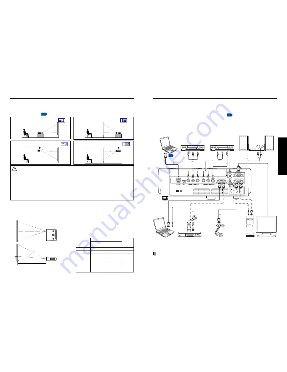
• The figure below is a sample connection. This does not mean that all of these devices

can or must be connected simultaneously. (Dotted lines mean items can be exchanged.)

Notes

• COMPUTER terminals 1 and 2 function identically.
• For TDP-T91, the document camera should be connected to COMPUTER terminal 2.
• The AUDIO IN terminal doubles for devices connected to COMPUTER terminals 1 and 2.

Connection

Projection Distance and Size

Use the figures, tables, and formulas below to determine the projection size and projection distance.
(Projection sizes are approximate values for full-size picture with no keystone adjustment.)

Placement Styles

As shown in the figures below, this device can be placed in 4 different styles.
The factory setting is “floor-mounted front projection.” Set the Projection mode in the
default setting menu 

p.32

, in accordance with your needs.

Placement

Floor-mounted front projection 

 WARNING

• Always obey the instructions listed in IMPORTANT SAFETY INSTRUCTIONS when placing the unit.

Attempting to clean/replace the lamp at a high site by yourself may cause you to drop down, thus
resulting in injury.

• If you wish to mount the projector on the ceiling, be sure to ask your dealer to do so. Mounting the

projector on a ceiling requires special ceiling brackets (sold separately) and specialized knowledge.
Improper mounting could cause the projector to fall, resulting in an accident.

• If the projector is ceiling-mounted, install the breaker for turning off the power in case of anomaly. Let

everyone involved with the use of the projector know that fact.

Floor-mounted rear projection 

Ceiling-mounted front projection 

Ceiling-mounted rear projection 

H

a

90

°

Screen

As seen from above

Lens center

As seen from the side

a (min length) = projection size (inches) 

×

 4.064

a (max length) = projection size (inches) 

×

 4.878

90

°

Computer (for control)

VCR

Video recorder,

DVD player, etc.

Audio amplifier, etc.

To RS-232C

terminal

Control cable

To audio output
White (L)/Red (R)

To video
output

AV cable

(not supplied)

Video cable (not supplied)

To S-Video
output

To audio output

White (L)/Red (R)

S-Video cable

(not supplied)

Audio cable

(not supplied)

To audio input
White (L)/Red (R)

To RGB
output

RGB cable

(not supplied)

Audio cable

(not supplied)

To audio
output

To Y/C

B

/C

R

 output

Green (Y)/Blue (C

B

)/Red (C

R

)

Conversion adapter BNC-pin
(not supplied)

Monitor cable Mini
D-sub 15P-BNC
(not supplied)

RGB cable
(supplied with
TDP-T91)

To audio output

Audio cable
(not supplied)

RGB cable
(supplied)

To RGB output

Computer

Document camera

Computer

DVD video recorder, etc.

a is the distance (m) between the lens and the
screen, and corresponds to a range of 1.20 m to
10.00 m. H is the height from the image bottom to
the center of the lens.

projection

projection distance a (m)

height (H)

min length

max length

size (inches)

(zooming max) (zooming min)

(cm)

24.6

1.20

5.6

40

1.62

1.95

9.1

60

2.44

2.93

13.8

80

3.25

3.90

18.3

100

4.00

4.88

22.9

150

6.10

7.30

34.3

200

8.10

9.76

45.7

246

10.00

56.2

Summary of Contents for TDP-T90

Page 1: ...Others Maintenance Operations Preparations Before Using OWNER S MANUAL DATA PROJECTOR TDP T90 XGA TDP T91 XGA With Document Camera ...

Page 2: ... A digital apparatus complies with Canadian ICES 003 Cet appareil numérique de la classe A est conforme à la norme NMB 003 du Canada WARNING This is a Class A product In a domestic environment this product may cause radio interference in which case the user may be required to take adequate measures USA only CANADA only USA only FCC NOTICE This device complies with part 15 of the FCC Rules Operatio...

Page 3: ...afeguards incorporated in this unit will protect you if you observe the following procedures for installation use and servicing This unit is fully transistorized and does not contain any parts that can be repaired by the user DO NOT REMOVE THE CABINET COVER OR YOU MAY BE EXPOSED TO DANGEROUS VOLTAGE REFER SERVICING TO QUALIFIED SERVICE PERSONNEL ONLY 1 Read Owner s Manual After unpacking this prod...

Page 4: ...to avoid injury and contact your dealer for repair service The broken pieces of glass may cause to injury In the unlikely event of the lamp rupturing thoroughly clean the area around the projector and discard any edible items placed in that area 18 Servicing Do not attempt to service this product yourself as opening or removing covers may expose you to dangerous voltage or other hazards Refer all ...

Page 5: ... that situation the malfunction may result Ensure to wait until the condensation naturally disappears In a high altitude location where air is thin cooling efficiency is reduced so use it with the ambient temperature being lowered POWER SUPPLY CORD SELECTION 19 Replacement Parts When replacement parts are required be sure the service technician has used replacement parts specified by the manufactu...

Page 6: ...XGA are trademarks or registered trademarks of International Business Machines Corporation Digital Light Processing Digital Micromirror Device and DMD are trademakes of Texas Instruments Macintosh is a registered trademark of Apple Computer Inc Windows is a registered trademark of Microsoft Corporation in the U S and other countries Adobe is a registered trademark and Acrobat Reader is a trademark...

Page 7: ...ng off the picture and sound temporarily Mute 28 Freezing the image Freeze 28 Using the menus 29 How to use the menus 29 The image adjustment menu 30 The display setting menu 31 The default setting menu 32 Displaying Information Status display 33 Using the document camera 34 How to use the document camera 34 Image projection with the document camera 36 Locking the white balance 37 Maintenance Abou...

Page 8: ...Windows Run the CD ROM select the Reader English folder and run ar500enu exe Follow the on screen instructions Macintosh Run the CD ROM select the Reader English folder and run Reader Installer Follow the on screen instructions to install the software Viewing the manual Run the CD ROM and double click on Start pdf Acrobat Reader launches and the menu screen of the Owner s manual appears Click on y...

Page 9: ...pment For TDP T91 use exclusively for document camera connection 12 Main power switch AC power line ON standby OFF 13 AC IN socket Connect the supplied power cord here 14 AUDIO IN terminal Input audio signals from a computer or video equipment with a component video signal output terminal 15 Antitheft lock hole Attach a safety cable or any other antitheft device Parts on the rear panel Names of ea...

Page 10: ... or bang Do not leave in hot or humid locations Do not get wet or place on top of wet objects Do not take apart In rare cases ambient conditions could impede the operation of the remote control If this happens point the remote control at the main unit again and repeat the operation Preparing and using the remote control 8 9 5 4 2 6 11 10 12 1 3 7 Name Function 1 Tray The document camera is mounted...

Page 11: ...ojector on a ceiling requires special ceiling brackets sold separately and specialized knowledge Improper mounting could cause the projector to fall resulting in an accident If the projector is ceiling mounted install the breaker for turning off the power in case of anomaly Let everyone involved with the use of the projector know that fact Floor mounted rear projection Ceiling mounted front projec...

Page 12: ...ng lamp During internal cooling After cooling complete A B C Orange Orange Green Green Off Orange Flashing Green Off Off A During cooling the LAMP indicator flashes In this state the power cannot be turned back on B After the LAMP indicator goes off the cooling fan continues to operate for a short while in order to expel excess internal heat If you are in a hurry there is no problem with unpluggin...

Page 13: ...ojector placement angle adjustments The placement angle and the height of the projected image can be adjusted by the foot adjuster q Lift up the front of the projector to the desired angle then press the foot adjuster release button The foot adjuster extends Release the button to lock the position w Turn the foot adjuster to fine tune the angle e To adjust the horizontal angle use the tilt adjuste...

Page 14: ...ay be lost or the picture quality may suffer Keystone adjustment is available for the keystone distortion in a slant angle of 15 degrees Keystone adjustment will not change the shape of the menus the start up screen and the background with no signal input Using handy features Control panel Remote Control Before correction After correction Manual adjustments and settings The menu items of the Set u...

Page 15: ...can call up on screen menus and conduct a number of adjustments and settings using the operation buttons p 16 on the control panel main unit side and remote control How to use the menus The menu shown below is for operation instructions purposes and might differ from the actual display Using the menus Note Menu adjustments and settings are saved when the power is turned off via the ON STANDBY butt...

Page 16: ...e document No No No Yes balance 2 camera TDP T91 Auto Lock 1 Tint and NTSC mode can be displayed and adjusted only when the video signal is set to NTSC and NTSC4 43 NTSC mode is set to JAPAN when the language is set to Japanese It is set to US for other languages 2 Even if the white balance is set to Lock turning the projector off disables this function and turning it on again the next time resets...

Page 17: ...erred to for customer service etc Note The displayed information will not be refreshed if the status changes To refresh the information dismiss the display then display it again The default setting menu This menu shows placement status and other settings Sets projection mode in accordance with Placement Style Set the timer to wait for the power to be turned off after signal input stops Press Switc...

Page 18: ...ke care not to bump yourself or others with it When placing the projector in the carrying bag remove the connection cables Otherwise damage to the connectors and cables may result Status before preparation When stored 1 Set up arm 2 Rotate arm 3 Raise camera head Using the camera removed from the projector PRECAUTIONS Installation of the document camera onto the tray should be performed in the rev...

Page 19: ...ing the document camera p 34 Notes There is no audio output when camera input is selected If the room s fluorescent lighting causes the image to flicker either turn off the fluorescent light or set the Shutter from the Image adjustment menu p 30 Note that changing the Shutter setting may not eliminate the flicker depending on the lighting state of the document or image adjustment Locking the white...

Page 20: ...r the life expires may vary greatly by lamp Some may explode shortly after first use Free replacement is available if the lamp explodes within the warranty period Contact the dealer from whom you purchased the product in such a case Explosion is likely to happen if the lamp is used after the replacement period has elapsed When the lamp explodes the broken pieces of glass may get inside the product...

Page 21: ...ne minute of abnormal display the projector returns to the standby state waiting for internal cool down Power went out during use Camera is not correctly connected Disconnect the power plug and check the connection with the camera The icon will appear before the power goes out After approx one minute of abnormal display the projector returns to the standby state waiting for internal cool down PREC...

Page 22: ...functioning properly Is the input signal supported by the projector p 45 p 46 Is there something generating an abnormal video signal for instance the video tape Is the lens dirty p 40 Is the lens focus adjusted optimally p 25 Is the projection distance within the projector s supported range p 20 Is the projector s screen placement angle tilted too far p 20 Are the sharpness or sampling phase adjus...

Page 23: ...ilitate recycling after this product becomes no longer usable Note Design specifications etc subject to change without notice for improvements etc Connection terminal List of supported signals RGB signals This projector supports the following RGB signals Note however that depending on the computer model the screen may show flicker or streaking Please adjust the projector if this happens Press the ...

Page 24: ...tal sync signal 14 Vertical sync signal 15 N C Specifications Continued Do not connect anything CONTROL terminal Pin assignment 7 6 8 5 4 3 2 1 Signal Name RXD CTS DSR GND RTS N C TXD GND Pin No 1 2 3 4 5 6 7 8 Description Receiving data Consent to send Data set ready Signal ground Request to send No connection Sending data Signal ground Mini DIN 8 pin connector Interface format 1 Communication me...

Page 25: ......

Reviews: