background image

15

Preparations

14

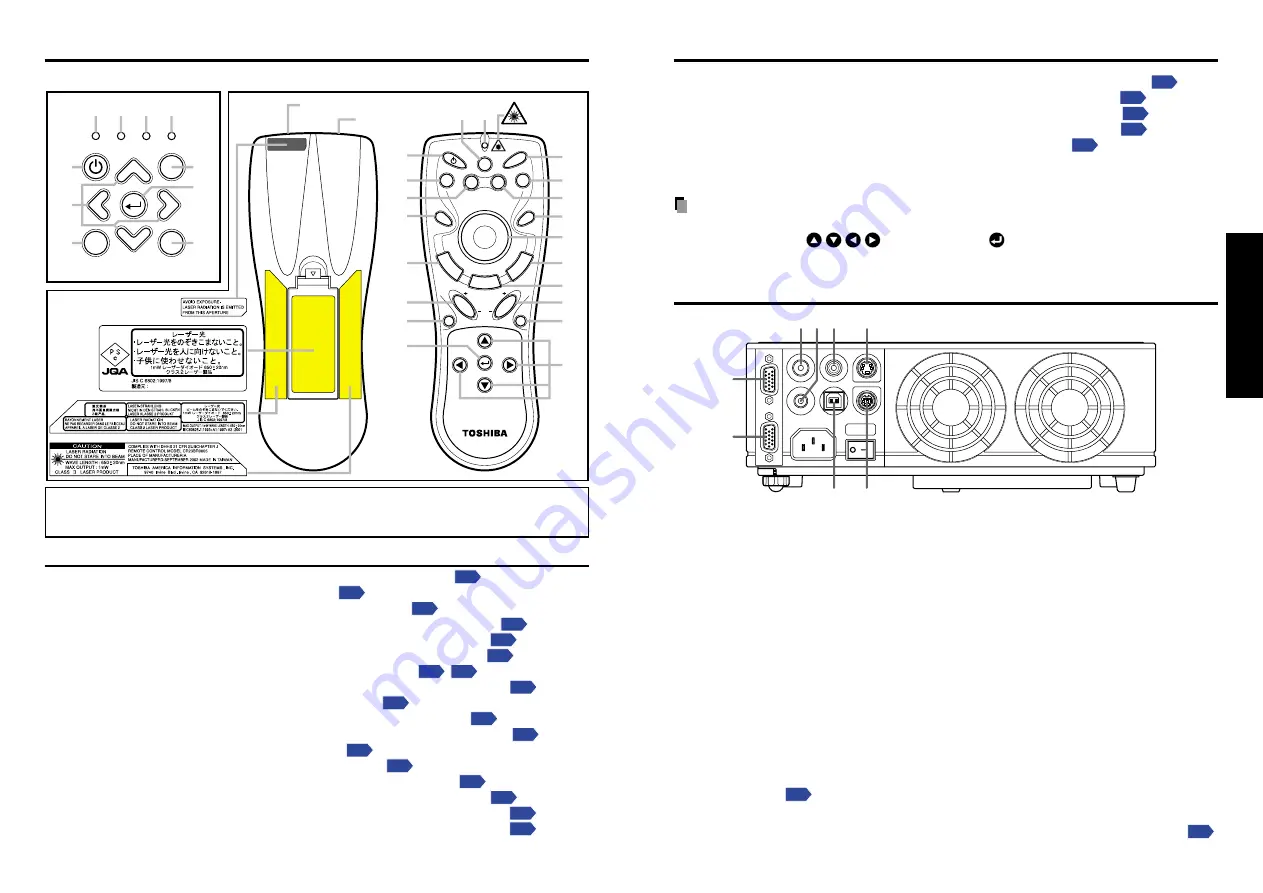
Names of each part on the control panel and remote control

Name

: Main Function

(1) ON/STANDBY button

: Turns the power on/off (standby) 

p.19

(2) INPUT button

: Selects input 

p.21

(3) AUTO SET button

: Sets up image and mode 

p.23

(4) AUTO KEYSTONE button

: Adjusts keystone (trapezoidal distortion) 

p.24

(5) MENU button

: Displays menus and makes selections 

p.27

(6) Selection button

: Menu selections and adjustments, etc.

p.27

(7) FAN indicator

: Displays cooling fan mode 

p.20


p.33

(8) TEMP indicator

: Lights when internal temperature too high 

p.33

(9) LAMP indicator

: Displays lamp mode 

p.20

(10) ON indicator

: Displays whether power is on or off 

p.19

(11) MUTE button

: Cuts off the picture and sound temporarily 

p.24

(12) FREEZE button

: Pauses image 

p.25

(13) RESIZE button

: Enlarges picture size 

p.25

(14) RESIZE OFF button

: Turns off enlarged picture display 

p.25

(15) CALL button

: Displays the information on the screen 

p.26

(16) PAGE DOWN button

: Canges page of file (Computer operation) 

p.30

(17) PAGE UP button

: Canges page of file (Computer operation) 

p.30

DRAG

R

-C

L

IC

K

L

-C

L

IC

K

RESIZE OFF

INPUT

MENU

VOL.+

VOL.-

AUTO

KEYSTONE

AUTO

SET

PAGE

UP

PAGE

     DOWN

FREEZE

MUTE

CALL

ON/STANDBY

LASER

RESIZE INPUT

Laser 

Warning

Remote control

transmitter

Laser emitter

Caution Label

(1)

(1)

(2)

(2)

(5)

(5)

(7)

(8)

(9)

(10)

(11)

(12)

(13)

(14)

(15) (24)

(16)

(17)

(18)

(19)

(20)

(21)

(22)

(23)

(4)

(4)

(6)

(6)

(3)

(3)

ON/STANDBY

INPUT

MENU

ON

LAMP

TEMP

FAN

AUTO KEYSTONE

AUTO SET

Control Panel

Remote Control

VOL.

+

VOL.

-

Caution

 - use of controls or adjustments or performance of procedures other

than those specified herein may result in hazardous radiation exposure.

(18) Pointer control button

: Moves mouce pointer (Computer operation) 

p.30

(19) L-CLICK button

: L-click of mouse (Computer operation) 

p.30

(20) R-CLICK button

: R-click of mouse (Computer operation) 

p.30

(21) DRAG button

: DRAG of mouse (Computer operation) 

p.30

(22) INPUT + - button

: Changes input source in order 

p.21

(23) LASER button

: Displays laser point

(24) Laser indicator

: Lights when laser point displaying

Notes

• For the remainder of this manual, buttons are referred to as follows:

Selection button 


; MENU button 


Names of the connection terminals

S-VIDEO

VIDEO

AUDIO IN

AUDIO OUT

USB

COMPUTER IN

MONIT

OR OUT

CONTROL

(1)

(6)

(4)

(7)

(8)

(5)

(3)

(2)

(1) COMPUTER IN terminal

Input RGB signal from a computer or other source, or a component video signal (Y/P

B

/

P

R

) from video equipment.

(2) MONITOR OUT terminal

Connect to a computer display, etc.

(3) AUDIO IN terminal

Input audio signals from a computer or video equipment.

(4) AUDIO OUT terminal

Outputs audio signals adjusted volume by a projector

(5) VIDEO terminal

Input video signals from video equipment.

(6) S-VIDEO terminal

Input S video signals from video equipment.

(7) CONTROL terminal

When operating the projector via a computer, connect this to the controlling computer’s
RS-232C port. 

p.38

(8) USB terminal

Connect to a computer’s USB port when using the remote-control mouse function. 

p.30

Summary of Contents for TDP-D1

Page 1: ...Others Maintenance Operations Preparations Before Using OWNER S MANUAL DLP DATA PROJECTOR TDP D1 TDP D2 ON ST AN DB Y INP UT ON LA MP TE MP FA N ME NU AU TO KE YS TO NE AU TO SE T VO L VO L ...

Page 2: ...ence to radio or television reception which can be determined by turning the equipment off and on the user is encouraged to try to correct the interference by one or more of the following measures Reorient or relocate the receiving antenna Increase the separation between the equipment and receiver Connect the equipment into an outlet on a circuit different from that to which the receiver is connec...

Page 3: ...RUCTIONS Continued 11 Object and Liquid Entry Never push objects of any kind into this product through openings as they may touch dangerous voltage points or short out parts that could result in a fire or electric shock Never spill liquid of any kind on the product 12 Do not place the product vertically Do not use the product in the upright position to project the pictures at the ceiling or any ot...

Page 4: ...ndle with care to avoid injury and contact your dealer for repair service The broken pieces of glass may cause to injury In the unlikely event of the lamp rupturing thoroughly clean the area around the projector and discard any edible items placed in that area 18 Servicing Do not attempt to service this product yourself as opening or removing covers may expose you to dangerous voltage or other haz...

Page 5: ...0 240V 200 240V Plug configuration Plug type Line voltage Use a 5A fuse which is approved by ASTA or BSI to BSI362 Always replace the fuse cover after changing the fuse IMPORTANT PRECAUTIONS Save Original Packing Materials The original shipping carton and packing materials will come in handy if you ever have to ship your projector For maximum protection repack the set as it was originally packed a...

Page 6: ...ccordance with local regulations Trademarks VGA SVGA XGA SXGA UXGA are trademarks or registered trademarks of International Business Machines Corporation Digital Light Processing DLP Digital Micromirror Device and DMD are trademakes of Texas Instruments Windows is a registered trademark of Microsoft Corporation in the U S and other countries Notational Conventions Used in This Manual References to...

Page 7: ...e Reader English folder and run ar500enu exe Follow the on screen instructions Macintosh In the CD ROM select the Reader English folder and run Reader Installer Follow the on screen instructions to install the software Viewing the manual In the CD ROM double click on Start pdf Acrobat Reader launches and the menu screen of the Owner s manual appears Click on your language The Owner s Manual cover ...

Page 8: ...DBY INPUT MENU ON LAMP TEMP FAN AUTO KEYSTONE AUTO SET Control Panel Remote Control VOL VOL Caution use of controls or adjustments or performance of procedures other than those specified herein may result in hazardous radiation exposure 18 Pointer control button Moves mouce pointer Computer operation p 30 19 L CLICK button L click of mouse Computer operation p 30 20 R CLICK button R click of mouse...

Page 9: ...6 m b is the distance cm between the lens center and the bottom of the projection image Screen As seen from above Lens center As seen from the side Operating the remote control Point the remote control toward the projector s infrared remote sensor and press a button on the remote control Operating the projector from the front ON STA ON Approx 15 Approx 5m Operating the projector from the rear COMP...

Page 10: ...on Read the owner s manual of the device to be connected to the projector Some types of computer cannot be used connected to this projector Check for an RGB output terminal supported signal p 36 etc Turn off the power of both devices before connection The figure below is a sample connection This does not mean that all of these devices can or must be connected simultaneously Dotted lines mean items...

Page 11: ...enu p 29 The first time you use the projector after purchase after the start up screen disappears the Language menu is displayed p 21 Turning the power off 1 Press the ON STANDBY button A message appears on the screen confirming that you wish to shut off the power This message will disappear after a moment This operation is no longer valid after the message disappears 2 Press the ON STANDBY button...

Page 12: ...ss the foot adjuster release button The foot adjuster extends Release the button to lock the position w Turn the foot adjuster to fine tune the angle e To adjust the horizontal angle use the tilt adjuster To stow the foot adjuster hold up the projector while pressing the foot adjuster release button then slowly lower the projector will the button depressed 6 Adjusting the picture size and focus q ...

Page 13: ... PAGE DOWN FREEZE MUTE CALL ON STANDBY LASER Remote Control DRAG R C L I C K L C L I C K RESIZE OFF INPUT MENU VOL VOL RESIZE INPUT 4 3 2 1 Remote Control Correcting the keystone distortion Keystone When the foot adjuster p 22 is used to change the projection angle the picture will undergo keystone trap ezoidal distortion This projector is capable of correcting this keystone distortion 1 Press the...

Page 14: ...tting display menu appears Pressing it again displays information p 27 The table below shows what kind of information is displayed Press the button or the CALL button on the remote control again to dismiss the display Yes displayed No not displayed Item Description Computer Y PB PR Video S video Input Input source name Yes Yes Yes Yes RGB signal mode RGB input mode Note 1 Yes No No No H resolution...

Page 15: ...r will come on Even if Power on is set to Auto press the ON STANDBY button to turn off the power Turning off the main power switch to cut off the power will shorten the life of the lamp The display setting menu Use this menu to set screen display related items Full Display with native resolution 1 024 x 768 pixels Thru Display with sampling resolution for computer input Wide Wide screen display fo...

Page 16: ...If the lamp should break please handle with care to avoid injury due to broken pieces and contact your dealer for repair service 1 Unplug power cord 2 Wait until lamp is sufficiently cooled Wait for at least 1 hour Lens and main unit cleaning A computer can be operated using the projector s remote control This function is available on any computer with the Windows 98SE Windows Me Windows 2000 Wind...

Page 17: ...the power cord repeatedly when the temperature is high will shorten the life of the lamp Even if you are not concerned about lamp lifetime the light may not come on if you do not wait at least 3 minutes Trouble indications FAN TEMP LAMP ON FAN TEMP LAMP ON FAN TEMP LAMP ON FAN TEMP LAMP ON Red lit Red lit Red lit Red lit Green lit Or Orange lit Or Orange lit Red lit or flashing Red lit 3 Remove th...

Page 18: ...nt temperature high p 33 Is the air intake or air exhaust blocked p 33 Is the input source selecting properly p 21 Is the mute function on p 24 Is the brightness setting minimized p 28 Are the connections set up correctly p 18 Are all the connected devices functioning properly Is a plug inserted to AUDIO OUT terminal p 18 Is the mute function on p 24 Is the volume setting minimized p 22 Are the co...

Page 19: ...B signals Note however that depending on the computer model the screen may show flicker or streaking Please adjust the projector if this happens Press the AUTO SET button and adjust automatically or manually p 23 Mode 720x400_85 VGA_60 VGA_72 VGA_75 VGA_85 SVGA_56 SVGA_60 SVGA_72 SVGA_75 SVGA_85 MAC16 XGA_43i XGA_60 XGA_70 XGA_75 XGA_85 MAC19 SXGA1_75 QuadVGA_60 QuadVGA_85 SXGA3_60 SXGA3_75 SXGA3_...

Page 20: ...ers supported 4 Replies Acknowledge ACK 06h CR 0Dh Data Succeed ACK 06h ESC 1Bh Failure No acknowledge NAK 15h If commands are to be sent consecutively wait for the replies from the projector before sending the next command Main Commands Note Contact your dealer for control cable and other commands Separately Sold Product Replacement Lamp Model NO for TDP D1 TDPLD1 for TDP D2 TDPLD2 Note Design sp...

Reviews: