– 6 –
EN
ES
ES
ES
ES
ES
ES
ES
ES
ES
ES
ES
ES
ES
ES
ES
ES
ES
ES
ES
ES
ES
ES
9
Installation for Front Panel Assembly
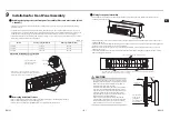
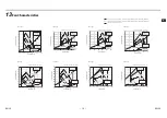
Sticking the sponge onto the front panel assembly (direct connection (only if 91
< D ≤ 101))
* This step is not required for direct connection (D = 91) and air duct connection. Please go to the next step “Removing
•
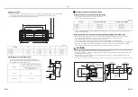
To extend the distance D (distance between the indoor unit and the wall) to more than 91 mm, cut 4 pieces (2 pieces in
length and 2 pieces in width) of heat insulation materials required for the extension (purchased locally). According to the
following table, stick the sponges against the mounting frame of panel assembly (1) (refer to the following figure).
* The maximum thickness of heat insulation material is 10 mm (D = 101). To extend more, please adjust the position of the
indoor unit or install it by the connecting air duct.
(Unit: mm)
Illustration for sticking sponge H and G
Removing horizontal louver
•
Remove the blue tapes in the center of the front panel assembly and on the leading part of the wire.
•
Remove the horizontal louver to prevent damage to it.
* Refer to the owner’s manual for the 3DW Diffusor for removing the horizontal louver.
Model
G Sponge (length × width)
H Sponge (length × width)
014 Type
652 × 15
120 × 15
018 Type
852 × 15
120 × 15
027 Type
1052 × 15
120 × 15
Stick sponges on the inner side of the air outlet (close to
the vertical louver that swing left and right), and the heat
insulation material shall not exceed the inner range
H Sponge
G Sponge
Screw hole
H Sponge
Do not block the screw
hole of panel assembly
(1) during sticking
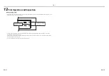
Fixing front panel assembly
•
First thread the connecting wire of the front panel assembly (1) to the wall opening, and then push the front panel
assembly (1) into the opening.
•
Temporarily fix two screws at the central part of the panel assembly (1) with the complimentary fixing screws for panel
assembly (M4x25) (4).
•
Similarly, after temporarily fixing the remaining 4 screws, tighten all the screws (6 in total). Pay attention to the tightening
sequence of the screws and ensure even force distribution.
•
When the clearance between front panel assembly and the wall is 1 mm or less and the clearance is even, please stop
tightening the screws.
•
Please ensure that there is no clearance between the indoor unit and the mounting frame, and between the mounting
frame and front panel assembly.
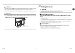
CAUTION
•
Over tightening the fixing screws for front panel assembly
(M4x25) (4) may cause damage. Therefore if the clearance
between front panel assembly and the wall is 1 mm or
less, please stop tightening the screws.
•
A clearance more than 1 mm between the outer periphery
of the front panel assembly (1) and the wall may result in
condensation. Please remove the front panel assembly (1),
readjust the distance between the indoor unit (it is the
mounting frame (2) if air duct is connected) and the wall,
and reinstall the front panel assembly (1).
•
If there is clearance between the indoor unit and the
mounting frame, and between the mounting frame and
front panel assembly, condensation may occur. Please
ensure that there is no clearance after installation.
Connecting wire
Temporarily fix two screws at the central part
Then temporarily fix the remaining 4 screws. Finally tighten all the screws (pay attention to the tightening
sequence of the screws and ensure that the force is even)
Wall
Front panel
assembly
Indoor unit
The clearance
between the
front panel
assembly and the
wall is 1 mm
EN-11
EN-12
Summary of Contents for TCB-TDL0141SDY-E
Page 12: ...D0X7203601 00 ...


