


Strata CT Installation
Strata CT I&M Manual October 2000
2-35
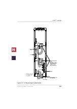
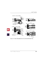
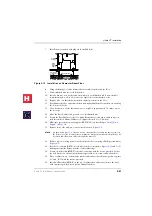
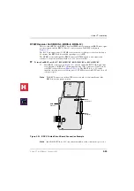
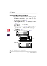
Reserve Power/AC Wiring for Three or More Cabinets (Floor
Mount)
➤
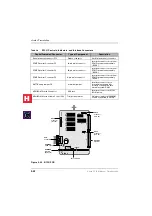
To connect reserve power to floor-mounted systems with three or more cabinets
See
and follow these steps:
1.
Make sure that the Conduit Connection Box is installed on the bottom base cabinet (see
). The box can be installed by the regular system installer.
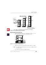
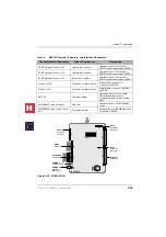
2.
Have a licensed electrician install conduit and battery cabling to the Conduit
Connection Box per local electrical codes. The remaining steps in this procedure can be
performed by the regular system installer (see
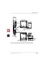
3.
Install the Battery Distribution Box on the second cabinet (the cabinet directly above the
bottom cabinet), see
.
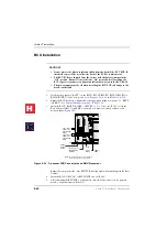
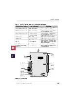
4.
Plug the two Conduit Connection Box cables (coming from the left side of the BCCB
box) into the Battery Distribution Box (BBDB).
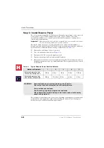
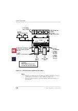
Important!
The cabinets must be connected to the (live) AC power source, and the power
supply On/Off switches set to On prior to the final step of connecting the
reserve power batteries to the power supplies via the BATT +/- receptacle. If
the batteries are connected after AC power is lost, reserve power will not
function.
5.
Connect cables from the (BBDB) Battery Distribution Box to the BATT +/- receptacle
of individual power supplies. BBTC2A-2M cables come with each BBDB distribution
box (see
).
6.
To test reserve power operation, turn off the system AC power circuit breaker with
power supply On/Off switches in the On position. The system should continue to
operate without interruption.
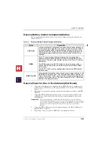
See
for battery specifications and wiring guidelines.
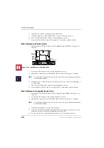
Step 6: Install Universal and Processor PCBs
This section provides procedures for the installation of Strata CT processor (or common
control) PCBs.
The Strata CT system Base and Expansion Cabinets are shipped empty. PCBs are not
installed at the factory. Universal PCBs must be placed according to the configuration
information obtained and developed in
Chapter 1 – Strata CT Configuration
. Processor PCB
of this chapter.
◆
Install PCBs only after installing the Base Cabinet and, if applicable, Expansion
Cabinets per the Cabinet Installation section in this chapter.
◆
Be sure the power supply has been tested and the ground has been checked (see
.
◆
Install universal slot PCBs per the Strata CT configuration guidelines (see
.
◆
Install the metal mesh shield, B50MT around the 25-pair cables connected to PCBs per
H
C
Summary of Contents for Strata CT
Page 36: ...Strata CT Configuration 1 22 Strata CT I M Manual October 2000 H C ...
Page 94: ...Strata CT Installation 2 58 Strata CT I M Manual October 2000 H C ...
Page 242: ...Peripheral Installation 6 54 Strata CT I M Manual October 2000 H C ...
Page 258: ...ACD Installation 7 16 Strata CT I M Manual October 2000 H C ...
Page 274: ...Fault Finding 8 16 Strata CT I M Manual October 2000 H C ...
Page 364: ...ISDN Interfaces 10 38 Strata CT I M Manual October 2000 H C ...
Page 370: ...Notes to Users A 6 Strata CT I M Manual October 2000 H C ...


