DK14 Installation
WSIU1 - Serial Interface Board
Strata DK I&M 6/00
1-19
DK14 Installa
ti
on
WSIU1 - Serial Interface Board
System:
DK14
Circuits per PCB:
two serial interface ports
Interfaces with:
SMDR connection for call accounting device
Caller ID Interface Box, Interface for local connection of DKi Admin PC
customer-provided external modem for remote maintenance from a PC with
DKi Admin
Older Version(s):
none
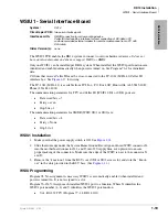
The WSIU1 PCB enables the DK14 system to connect to various hardware devices.
It does not
have an internal modem and does not support IMDU or RMDS.
Only one WSIU1 can be installed per DK14 system. When installed, the WSIU1 port functions are
identified and enabled automatically when power is turned on. See Program 76-1 for initialized
data.
CO lines that receive Caller ID must be cross-connected to the TC-1041 (MLX-41) Caller ID
interface box. See
for wiring.
The TC-1041 (MLX-41) is available from TCI, Inc., P.O. Box 4087, Huntsville, AL 35815-4087.
Phone (256) 881-4000.
The communication parameters for TTY and Caller ID (WSIU1 SI01 or SI02) ports are:
♦
Data word bits = 7
♦
Parity = even
♦
Stop bits = 1
The communication parameters for SMDR (WSIU SI01 or SI02) are:
♦
Data word bits = 8
♦
Parity = None
♦
Stop bit = 1
WSIU1 Installation
1. Make sure that the power supply switch is Off. See
.
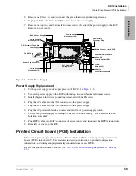
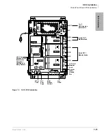
2. Slide the front edge under the System Frame Ground Bar. Align and insert WSIU connector J4
into the motherboard connector J21, and J3 into J20. Apply firm, even pressure to ensure
proper making of the connectors. Make sure the edge of the WSIU is next to the connector J1
and J2.
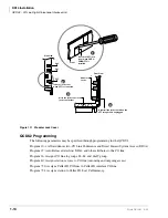
3. Remove the “knock-out” from the KSU cover SI01 or SI02 access slot, and store the “knock-
out” in the slots provided in the KSU base. (See
.)
WSIU Programming
Program 03: No assignment is necessary. WSIU1 is automatically enabled when installed and
power is turned On. It is not assigned to a slot.
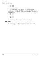
Program 76-1X-Y: Assigns each installed WSIU1 port to a function. Where X identifies the
WSIU1 port number (1~2) and Y identifies the WSIU1 port function:
♦
Y=1, RS-232 TTY (Program 77-1, LED 14 Off)
Summary of Contents for Strata AirLink DK40i
Page 22: ...Introduction Related Documents Media xx Strata DK I M 6 00 ...
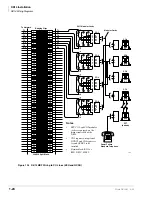
Page 48: ...DK14 Installation DK14 Wiring Diagrams 1 26 Strata DK I M 6 00 ...
Page 220: ...DK424 Installation Remote Cabinet Installation Instructions 5 68 Strata DK I M 6 00 ...
Page 262: ...DK424i Configuration Primary Reserve Power Cabinet Hardware 6 42 Strata DK I M 6 00 ...
Page 450: ...Universal Slot PCB Wiring Option Interface PCB Wiring Diagrams 10 42 Strata DK I M 6 00 ...
Page 592: ...Peripheral Installation Enhanced 911 Service E911 12 84 Strata DK I M 6 00 ...
Page 616: ...ACD Installation Spectrum Electronic Wall Boards 13 24 Strata DK I M 6 00 ...
Page 634: ...Fault Finding Fault Isolation Flowcharts 14 18 Strata DK I M 6 00 ...
Page 704: ...ISDN Interfaces ISDN Disconnect Cause Code 16 54 Strata DK I M 6 00 ...

