DK424i Installation
Step 5: Install Reserve Power
7-32
Strata DK I&M 6/00
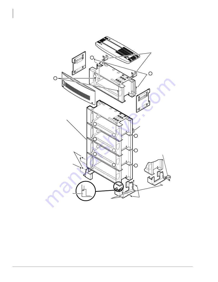
Figure 7-17 DK424i Cabinet Floor Installation
Important!
●
BFIF (two-each) and RWBFA (six-each) are supplied with the floor installation kit BFIF.
●
Upper and third cabinets must be fixed to the wall with RWBFS on each side (use #12 x 1.25
wood screws and wall anchors, as required).
●
Floor fixture (BFIF) must be fixed to floor by either anchor bolts, or wall by RWBF wall
brackets (see
and
).
A
B
Front (2)
Mouting
Screws
Provided
with BFIF Kit
Top Cabinet Wall
Securing Brackets
(RWBF)
(Left and
Right Side)
Back (2) Mounting
Screws Provided
with BFIF Kit
B
B
B
B
Bottom Wall
Securing Bracket
(RWBF)
Third Cabinet Wall
Securing Bracket
(RWBF)
(Left and right side)
B
B
A
A
A
B
BFIF
Mounting
Screws
Base Cabinet
(bottom)
BFIF is
inside of
cabinet edge
BFIF
Mounting Screws
Floor
Fixture
(BFIF)
Anchor
Bolts (2)
Anchor
Bolts (2)
5042
B
A
A
A
B
B
1
Summary of Contents for Strata AirLink DK40i
Page 22: ...Introduction Related Documents Media xx Strata DK I M 6 00 ...
Page 48: ...DK14 Installation DK14 Wiring Diagrams 1 26 Strata DK I M 6 00 ...
Page 220: ...DK424 Installation Remote Cabinet Installation Instructions 5 68 Strata DK I M 6 00 ...
Page 262: ...DK424i Configuration Primary Reserve Power Cabinet Hardware 6 42 Strata DK I M 6 00 ...
Page 450: ...Universal Slot PCB Wiring Option Interface PCB Wiring Diagrams 10 42 Strata DK I M 6 00 ...
Page 592: ...Peripheral Installation Enhanced 911 Service E911 12 84 Strata DK I M 6 00 ...
Page 616: ...ACD Installation Spectrum Electronic Wall Boards 13 24 Strata DK I M 6 00 ...
Page 634: ...Fault Finding Fault Isolation Flowcharts 14 18 Strata DK I M 6 00 ...
Page 704: ...ISDN Interfaces ISDN Disconnect Cause Code 16 54 Strata DK I M 6 00 ...


