DK424 Installation
RCTUA, RCTUBA/BB, RCTUC/D, RCTUE/F Common Control Units
Strata DK I&M 6/00
5-51
DK424 Installa
tion
RCTU Installation
CAUTION!
1. Do not remove the plastic insulation shield from the back of the RCTU PCB. If the
shield comes off, do not allow the back of the PCB to contact metal.
2. The RCTU PCBs are shipped from the factory with the battery jumper in the “Off”
position. Ensure it is moved to the “On” position before installing the RCTU to
protect customer configuration information stored in the RCTU RAM.
3. The power supply must be off when installing the RCTU PCB or damage to the
board could result.
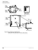
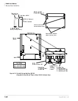
1. Set the P5, P8 or P9 battery jumper on the RCTUA, BA3, C3, D3, or RCTUF3 to the “On”
position (see
2. Ensure the RCTU has been configured for the appropriate hardware options (i.e., RRCS or
RKYS). See
“Internal Hardware Options” on Page 5-48
.
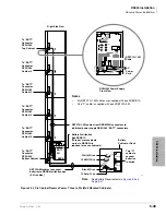
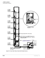
3. Insert the RCTUA, RCTUBB, RCTUD, or RCTUF (1, 2 or 3) into the “RCTU” slot in the
Base Cabinet. If RCTUA and RSIU is installed, you must also install a ribbon cable between
them (
“RSIU, RSIS, RMDS – RS-232/Modem Interface Unit” on Page 9-49
Ensure the component side of the RCTU PCB is facing right when installing it in the Base
Cabinet.
4. Insert the RCTUBA, RCTUC, or RCTUE PCB into slot R11.
5. After installing the RCTU PCBs, gently pull it outward. If the connectors are properly mated,
a slight resistance will be felt.
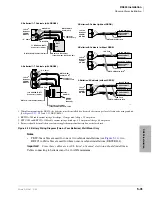
6. Connect the supplied ribbon cables between RCTUA, RCTUBA and BB and RSIU, if
installed; or RCTUC/D, RCTUE/F, and RSIU, if installed.
Note
Do not adjust the C14 or C15 trimmer capacitor. The capacitor is factory-calibrated.
CAUTION!
When transporting the RCTU PCBs, keep the P8 or P9 battery jumper in the
“On” position in order to save the configuration data stored in RCTU RAM.
(The battery will protect RAM for approximately six years.) Otherwise, to
conserve the lithium battery, move the jumper to the “Off” position.
When packaging the RCTU PCB, use only a nonconducting material enclosure, such as plain
cardboard. Conductive material can cause the internal battery to discharge and erase memory in
the RCTU PCB.
RCTU Programming
After initially installing a new and unused common control unit, all on-board RAM memory needs
to be erased and initialized by running Program 91-9 twice after all other PCBs are installed. If
RAM contains configuration or feature data from previous programming that should be retained,
do not run Program 91-9. See the
Strata DK Programming Manual.
Summary of Contents for Strata AirLink DK40i
Page 22: ...Introduction Related Documents Media xx Strata DK I M 6 00 ...
Page 48: ...DK14 Installation DK14 Wiring Diagrams 1 26 Strata DK I M 6 00 ...
Page 220: ...DK424 Installation Remote Cabinet Installation Instructions 5 68 Strata DK I M 6 00 ...
Page 262: ...DK424i Configuration Primary Reserve Power Cabinet Hardware 6 42 Strata DK I M 6 00 ...
Page 450: ...Universal Slot PCB Wiring Option Interface PCB Wiring Diagrams 10 42 Strata DK I M 6 00 ...
Page 592: ...Peripheral Installation Enhanced 911 Service E911 12 84 Strata DK I M 6 00 ...
Page 616: ...ACD Installation Spectrum Electronic Wall Boards 13 24 Strata DK I M 6 00 ...
Page 634: ...Fault Finding Fault Isolation Flowcharts 14 18 Strata DK I M 6 00 ...
Page 704: ...ISDN Interfaces ISDN Disconnect Cause Code 16 54 Strata DK I M 6 00 ...


