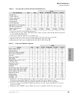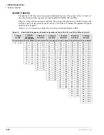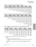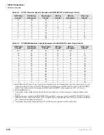
DK424 Configuration
Printed Circuit Boards
4-12
Strata DK I&M 6/00
Printed Circuit Boards
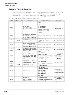
The system interfaces with CO lines, stations, and peripheral devices via PCBs that plug into the
Base and Expansion Cabinet slots and subassembly PCBs, that mount onto the plug-in type PCBs.
for a list of station and console PCBs supported by the DK424.
Table 4-17
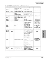
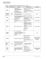
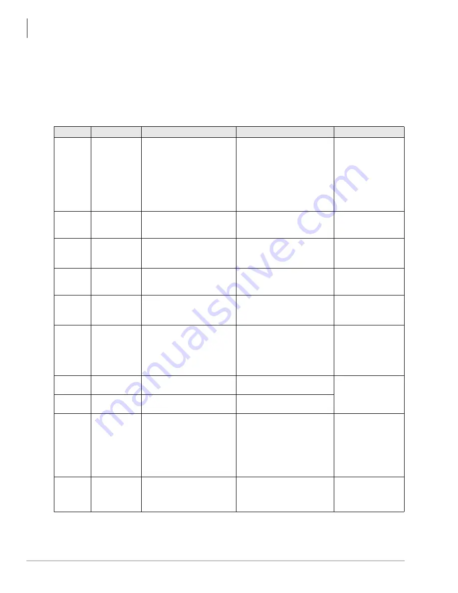
PCB Circuits, Interface Options and Connectors
PCB
Subassembly
Circuits
Interface Options
Connector
RPTU
(DK424 only)
1 circuit/ISDN PRI
(23 B channels/1 D channel)
POTS
FX
Tie (senderized)
Tie (cut through)
OUTWATS (intra-LATA)
OUTWATS (inter-LATA)
InWATS
RJ48C or RJ48X
ISDN TIA-568A
RBSU
2 ISDN BRI S/T point circuits
(NT or TE). Each circuit is
2B+1D. (Host for the RBSS)
Network and/or station side
RJ45, ISDN TIA-568A
attaches to
RBSU
RBSS
2 ISDN BRI, S point circuits
(2B+D each)
Station side only
1 RBSS subassembly per
RBSU
RJ45, ISDN TIA-568A
RBUU
(DK424 only) 2 ISDN BRI, U
point circuits (2B+D each).
Host for the RBUS. (R4.3)
Network and/or station side
RJ45, ISDN TIA-568A
attaches to
RBUU
RBUS
2 ISDN BRI, U point circuits
(2B+D each) subassembly for
the RBUU. (R4.3)
Network and/or station side
1 RBUS subassembly per
RBUU.
RJ45, ISDN TIA-568A
RDTU2
Applies to DK424 only.
1~8, 1~16, or 1~24 channels
(lines), depends on system
programming
Loop start lines
Ground start lines
Tie lines (wink or immediate)
DID/DOD lines (wink or
immediate)
2-pair amphenol
RJ48M
(All PCB amphenol
connectors are
female)
RMCU
2 E911 CAMA circuits with the
1 RCMS or 4 with 2 RCMSs
E911 CAMA lines
RJ11C modular
attaches to
RMCU
RCMS
2 E911 CAMA circuits
Up to 2 RCMSs per RMCU for
4 CAMA lines max.
REMU
4 Tie line circuits
E&M Tie lines
2- or 4-wire transmission
Type I signaling
Type II signaling
Immediate start
Wink start
REMU (8-wire
modular jack)
2- or 4-wire/type I or II
KCDU
(DK40i only)
2 CO line circuits/
4 digital telephone circuits
CO loop start lines
Digital circuits same as PDKU,
except no DDSS
RJ14C modular (CO
Line circuits)
25-pair amphenol
(digital phone circuits)
Summary of Contents for Strata AirLink DK40i
Page 22: ...Introduction Related Documents Media xx Strata DK I M 6 00 ...
Page 48: ...DK14 Installation DK14 Wiring Diagrams 1 26 Strata DK I M 6 00 ...
Page 220: ...DK424 Installation Remote Cabinet Installation Instructions 5 68 Strata DK I M 6 00 ...
Page 262: ...DK424i Configuration Primary Reserve Power Cabinet Hardware 6 42 Strata DK I M 6 00 ...
Page 450: ...Universal Slot PCB Wiring Option Interface PCB Wiring Diagrams 10 42 Strata DK I M 6 00 ...
Page 592: ...Peripheral Installation Enhanced 911 Service E911 12 84 Strata DK I M 6 00 ...
Page 616: ...ACD Installation Spectrum Electronic Wall Boards 13 24 Strata DK I M 6 00 ...
Page 634: ...Fault Finding Fault Isolation Flowcharts 14 18 Strata DK I M 6 00 ...
Page 704: ...ISDN Interfaces ISDN Disconnect Cause Code 16 54 Strata DK I M 6 00 ...


