


43
Advanced playback
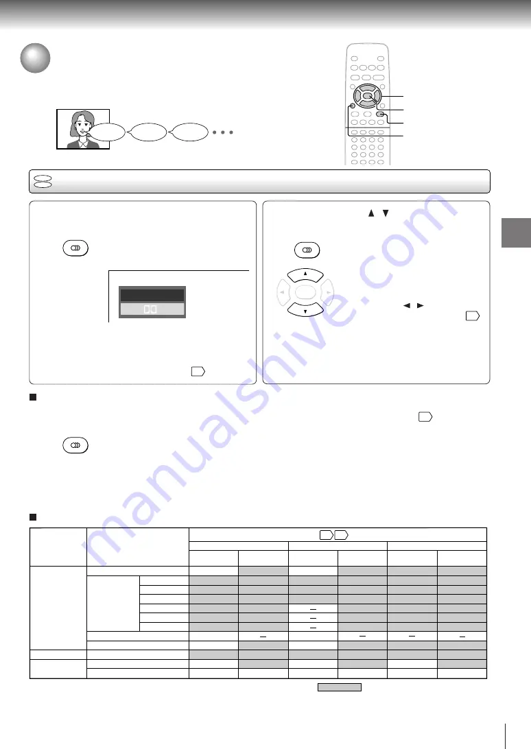
Selecting a Language
You can select a preferred language and sound recording system from those
included on the DVD video disc.
Selecting a playback audio setting
Press AUDIO during playback.
The current audio setting is
displayed.
The abbreviation of the language appears instead
of the language name. Refer to the list of
languages and their abbreviations.
57
Output sound conversion table (sampling frequency/quantization bit)
1
2
2
ENTER
1, 2
CLEAR
DVD
VCD
AUDIO
AUDIO
ENTER
Good morning!
¡Buenos días!
Bonjour!
BITSTREAM/PCM
jack
ANALOG AUDIO
OUT jacks
BITSTREAM/PCM
jack
ANALOG AUDIO
OUT jacks
BITSTREAM/PCM
jack
ANALOG AUDIO
OUT jacks
“Bitstream”
“Analog 2ch”
“PCM”
Audio selection from the menu
and output jacks on the rear panel
Recording system
Discs
DVD video
discs
Audio CDs
VIDEO CDs
Linear PCM
Dolby Digital
DTS
MPEG1, MPEG2
Linear PCM 44.1 kHz/16 bit
48 kHz/20 bit
48 kHz/16 bit
48 kHz/16 bit
48 kHz/16 bit
48 kHz/20 bit
48 kHz/24 bit
96 kHz/16 bit
96 kHz/20 bit
96 kHz/24 bit
48 kHz/16 bit
48 kHz/16 bit
48 kHz/16 bit
48 kHz/16 bit
48 kHz/16 bit
48 kHz/16 bit
48 kHz/16 bit
48 kHz/20 bit
48 kHz/24 bit
48 kHz/16 bit
48 kHz/20 bit
48 kHz/24 bit
Bitstream
Bitstream
Bitstream
Bitstream
44.1 kHz/16 bit
44.1 kHz/16 bit
Bitstream
Bitstream
48 kHz/16 bit
48 kHz/20 bit
48 kHz/16 bit
48 kHz/20 bit
48 kHz/24 bit
96 kHz/16 bit
96 kHz/20 bit
96 kHz/24 bit
48 kHz/16 bit
48 kHz/20 bit
48 kHz/24 bit
48 kHz/16 bit
48 kHz/20 bit
48 kHz/24 bit
48 kHz/16 bit
48 kHz/16 bit
48 kHz/16 bit
48 kHz/16 bit
48 kHz/16 bit
48 kHz/16 bit
44.1 kHz/16 bit
44.1 kHz/16 bit
48 kHz/20 bit
44.1 kHz/16 bit
44.1 kHz/16 bit
48 kHz/16 bit
48 kHz/16 bit
48 kHz/16 bit
MPEG1
44.1 kHz/16 bit
44.1 kHz/16 bit 44.1 kHz/16 bit
44.1 kHz/16 bit
44.1 kHz/16 bit 44.1 kHz/16 bit
51
48
: 3D sound enhancement can function.
DTS
(Noise)
Bitstream
(Noise)
Bitstream
(Noise)
Bitstream
48 kHz/16 bit
48 kHz/16 bit
Press AUDIO or / while the audio
setting is displayed on the TV screen.
Each time you press the AUDIO
button, the audio settings included
on the DVD video disc change.
If you press the / buttons, you
can select output sound format.
51
To turn off the audio setting display, press the
CLEAR or ENTER button.
Selecting sound channels of VIDEO CDs
You can switch left and right channels by pressing the
AUDIO button repeatedly during playback.
Notes
• When you turn on the DVD video player or replace a disc,
player returns to the initial default setting
52
.
If you select a sound track which is not included on the disc,
the DVD video player plays a prior sound track programmed
on the disc.
• Some discs allow you to change audio selections only via
the disc menu. If this is the case, press the MENU button
and choose the appropriate language from the selections on
the disc menu.
ENG2 D 2CH
ENG1 PCM 2CH
e.g.
AUDIO
Summary of Contents for SD-120EB
Page 19: ......
Page 27: ......
Page 49: ......
Page 61: ......
Page 62: ...Others Before Calling Service Personnel Specifications ...
Page 105: ...4 2 Power Supply Block Diagram Fig 3 4 2 ...
Page 107: ...Fig 3 4 5 4 3 3 Front Display Power Switch Block Diagram ...
Page 108: ...m Q502 Q501 PUDET2 IC306 Fig 3 4 6 4 4 Main Block Diagrams 4 4 1 Servo System Block Diagram ...
Page 110: ...4 4 3 Output RGB Block Diagram Fig 3 4 8 ...
Page 113: ...10 1 3 4 A B C D E G 2 5 6 7 8 9 F Fig 3 5 3 5 2 Front Display Power Switch Circuit Diagram ...
Page 116: ...5 3 2 Main Circuit Diagram Fig 3 5 5 ...
Page 117: ...5 3 2 Main Circuit Diagram ...
Page 118: ......
Page 119: ......
Page 120: ......
Page 121: ......
Page 122: ......
Page 123: ......
Page 124: ...Fig 3 5 5 ...
Page 126: ...10 1 3 4 A B C D E G 2 5 6 7 8 9 F 5 4 Output RGB Circuit Diagram Fig 3 5 7 ...
Page 137: ......
Page 138: ......


