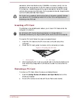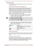
background image

2.

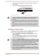
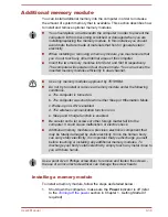
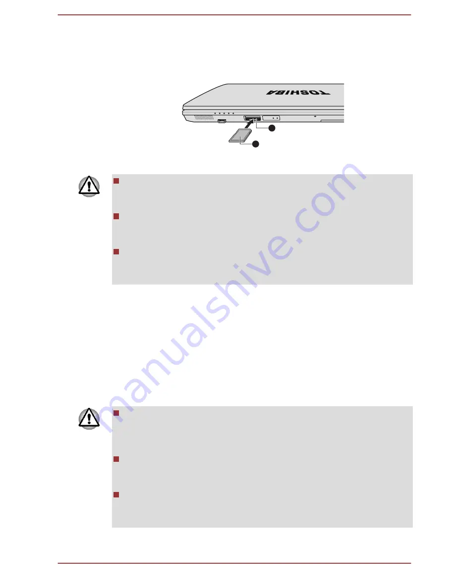
Insert the memory media into the memory media slot on the front of
the computer.

3.

Press the memory media gently until you hear a click.

Figure 3-14 Inserting a memory media

1

2

1. Memory media slot

2. Memory media

Make sure memory media is oriented properly before you insert it. If
you insert the media in wrong direction, you may not be able to
remove it.
When inserting memory media, do not touch the metal contacts. You
could expose the storage area to static electricity, which can destroy
data.
Do not turn the computer off or switch to Sleep Mode or Hibernation
Mode while files are being copied - doing so may cause data to be
lost.

Removing a memory media

The following instructions apply to all types of supported media devices. To
remove a memory media, follow the steps as detailed below:
1.

Open the 

Safely Remove Hardware and Eject Media

 icon on the

Windows Taskbar.

2.

Point to 

memory media

 and click the left Touch Pad control button.

3.

Press the memory media to partially extend it out of the computer.

4.

Grasp the media and remove it.

Make sure the Memory Media slot indicator is out before you remove
the memory media or turn off the computer’s power. If you remove the
memory media or turn off the power while the computer is accessing
the memory media, you may lose data or damage the media.
Do not remove the memory media while the computer is in Sleep or
Hibernation Mode. The computer could become unstable or data in
the memory media could be lost.
Do not remove only the Memory Stick Duo/Memory Stick PRO Duo/
Memory Stick Micro/miniSD/microSD Card while leaving the adaptor in
the memory media slot.

User's Manual

3-38

Summary of Contents for Satellite Pro S850

Page 1: ...User s Manual Satellite Pro S850 Series ...

Page 2: ... 8 Optical disc drives 3 14 TOSHIBA Disc Creator 3 20 TOSHIBA VIDEO PLAYER 3 22 Modem 3 24 Wireless communications 3 27 LAN 3 31 Optional devices 3 32 ExpressCard 3 32 PC Card 3 33 Memory media 3 35 Additional memory module 3 39 External monitor 3 43 Mini DisplayPort 3 44 eSATA External Serial ATA device 3 45 Serial port 3 46 Security lock 3 46 Optional TOSHIBA Accessories 3 47 Sound System 3 47 V...

Page 3: ...26 System Recovery 4 28 Chapter 5 Power and Power Up Modes Power conditions 5 1 Monitoring of power condition 5 2 Battery 5 3 Power up modes 5 9 Panel power on off 5 10 System automatic Sleep Hibernation 5 10 Chapter 6 Troubleshooting Problem solving process 6 1 Hardware and system checklist 6 4 TOSHIBA support 6 20 Appendix A Specifications Appendix B AC Power Cord and Connectors Appendix C Legal...

Page 4: ...ctions and descriptions it contains are accurate for your computer at the time of this manual s production However succeeding computers and manuals are subject to change without notice TOSHIBA assumes no liability for damages incurred directly or indirectly from errors omissions or discrepancies between the computer and the manual Trademarks Intel Intel SpeedStep Intel Core and Centrino are tradem...

Page 5: ...and on the user is encouraged to try to correct the interference by one or more of the following measures Reorient or relocate the receiving antenna Increase the separation between the equipment and receiver Connect the equipment into an outlet on a circuit different from that to which the receiver is connected Consult the dealer or an experienced radio TV technician for help Only peripherals comp...

Page 6: ...omplies with the Ecodesign Directive 2009 125 EC ErP and its related implementing measures This product and the original options are designed to observe the related EMC Electromagnetic Compatibility and safety standards However TOSHIBA cannot guarantee that this product still observes these EMC standards if options or cables not produced by TOSHIBA are connected or implemented In this case the per...

Page 7: ...e respectively should be asked for permission before use of this product Furthermore for general safety reasons the use of this product in environments with explosive atmospheres is not permitted VCCI Class B Information この装置は クラスB情報技術装置です この装置は 家庭環境で使 用することを目的としていますが この装置がラジオやテレビジョン 受信機に近接して使用されると 受信障害を引き起こすことがあります 取扱説明書に従って正しい取り扱いをしてください VCCI B Video Standard Notice THIS PRODUCT IS LICENSED UNDE...

Page 8: ...atement The equipment has been approved to Commission Decision CTR21 for pan European single terminal connection to the Public Switched Telephone Network PSTN However due to differences between the individual PSTNs provided in different countries regions the approval does not of itself give an unconditional assurance of successful operation on every PSTN network termination point In the event of p...

Page 9: ...ck Listed If you are experiencing problems with the Black Listed code set the interval between redials at one minute or longer Japan s Telecommunications Business Law permits up to two redials on analogue telephones but the redials must be made within a total of three minutes The internal modem is approved by Japan Approvals Institute for Telecommunications Equipment A05 0413001 This label is loca...

Page 10: ... best service it can In order to do this it may occasionally be necessary for them to make changes in their equipment operations or procedures If these changes might affect your service or the operation of your equipment the telephone company will give you notice in writing to allow you to make any changes necessary to maintain uninterrupted service If problems arise If any of your telephone equip...

Page 11: ... Technical Requirements document s The Department does not guarantee the equipment will operate to the user s satisfaction Before installing this equipment users should ensure that it is permissible to be connected to the facilities of the local telecommunications company The equipment must also be installed using an acceptable method of connection The customer should be aware that compliance with...

Page 12: ...stralia and New Zealand Modem warning notice for Australia Modems connected to the Australian telecoms network must have a valid Austel permit This modem has been designed to specifically configure to ensure compliance with Austel standards when the country region selection is set to Australia The use of other country region setting while the modem is attached to the Australian PSTN would result i...

Page 13: ...on the equipment PC associated with this modem The associated equipment shall be set to operate within the following limits for compliance with Telecom Specifications 1 There shall be no more than 10 call attempts to the same number within any 30 minute period for any single manual call initiation and 2 The equipment shall go on hook for a period of not less than 30 seconds between the end of one ...

Page 14: ...to computer 0 9 8 7 6 5 4 3 2 1 Note that where DTMF dialing is used the numbers should be entered normally The transmit level from this device is set at a fixed level and because of this there may be circumstances where the performance is less than optimal Before reporting such occurrences as faults please check the line with a standard Telepermitted telephone and only report a fault if the phone...

Page 15: ...tact your local city office or the shop where you purchased the product Disposal of batteries and or accumulators The crossed out wheeled dust bin symbol indicates that batteries and or accumulators must be collected and disposed of separately from household waste If the battery or accumulator contains more than the specified values of lead Pb mercury Hg and or cadmium Cd defined in the Battery Di...

Page 16: ...eable batteries After repeated use the batteries will finally lose their ability to hold a charge and you will need to replace them Under certain applicable laws and regulation it may be illegal to dispose of old batteries by placing them in the trash Please be kind to our shared environment Check with your local government authority for details regarding where to recycle old batteries or how to d...

Page 17: ...d has designed this computer to meet the latest ENERGY STAR guidelines for energy efficiency Your computer ships with the power management options preset to a configuration that will provide the most stable operating environment and optimum system performance for both AC power and battery modes To conserve energy your computer is set to enter the low power Sleep Mode which shuts down the system an...

Page 18: ...ire maintenance contact an authorized service location Use of controls adjustments or the performance of procedures other than those specified may result in hazardous radiation exposure To prevent direct exposure to the laser beam do not try to open the enclosure 1 Panasonic Precision Devices Co Ltd DVD SuperMulti with Double Layer Panasonic Precision Devices Co Ltd 1080 Takano Nagomi machi Tamana...

Page 19: ...T To use this model properly read the instruction manual carefully and keep this manual for your future reference In case of any trouble with this model please contact your nearest AUTHORIZED service station To prevent direct exposure to the laser beam do not try to open the enclosure User s Manual xix ...

Page 20: ...Acronyms are also defined in the Glossary Icons Icons identify ports dials and other parts of your computer The indicator panel also uses icons to identify the components it is providing information on Keys The keyboard keys are used in the text to describe many computer operations A distinctive typeface identifies the key top symbols as they appear on the keyboard For example ENTER identifies the...

Page 21: ... use of equipment or failure to follow instructions may cause data loss or damage your equipment Please read A note is a hint or advice that helps you make best use of your equipment Terminology This term is defined in this document as follows Start The word Start refers to the button in Windows 7 HDD or Hard disk drive Some models are equipped with a Solid State Drive SSD instead of a hard disk d...

Page 22: ... computer Always operate your computer on a hard flat surface Using your computer on a carpet or other soft material can block the vents Always provide sufficient space around the computer Overheating your computer or AC adaptor could cause system failure computer or AC adaptor damage or a fire possibly resulting in serious injury Creating a computer friendly environment Place the computer on a fl...

Page 23: ...he AC adaptor you should disconnect it and let it cool before moving it Do not lay the AC adaptor on a material that is sensitive to heat as the material could become damaged Pressure or impact damage Do not apply heavy pressure to the computer or subject it to any form of strong impact as this can damage the computer s components or otherwise cause it to malfunction PC Card ExpressCard overheatin...

Page 24: ... the following items TOSHIBA Portable Personal Computer AC adaptor and power cord 2 pin plug or 3 pin plug Battery pack Is preinstalled in some computers Documentation User Information Guide Instruction Manual for Safety and Comfort If any of the items are missing or damaged contact your dealer immediately Software The following Windows operating system and utility software are pre installed Windo...

Page 25: ...chance of developing a painful or disabling injury to your hand arms shoulders or neck This section provides basic information to start using your computer It covers the following topics Connecting the AC adaptor Opening the display Turning on the power Starting up for the first time Turning off the power Restarting the computer Use a virus check program and make sure it is updated regularly Never...

Page 26: ...ower cables that comply with the legal voltage and frequency specifications and requirements in the country of use Failure to do so could result in a fire or electric shock possibly resulting in serious injury The supplied power cord conforms to safety rules and regulations in the region the product is bought and should not be used outside this region For use in other regions please buy power cord...

Page 27: ...omputer Figure 1 3 Connecting the DC output plug to the computer 1 2 1 DC IN 15V jack 2 DC output plug 3 Plug the power cord into a live wall outlet the Battery and DC IN indicators on the front of the computer should glow Opening the display The display panel can be opened to a wide range of angles for optimal viewing While holding down the palm rest with one hand so that the main body of the com...

Page 28: ...l and the keyboard When opening or closing the display panel place one hand on the palm rest to hold the computer in place and use the other hand to slowly open or close the display panel Do not use excessive force when opening or closing the display panel Turning on the power This section describes how to turn on the power the Power indicator will then indicate the status Please refer to the Moni...

Page 29: ...ep Mode Shut Down Mode When you turn off the power in Shut Down Mode no data will be saved and the computer will boot to the operating system s main screen the next time it is turned on 1 If you have entered data either save it to the hard disk drive or to other storage media 2 Make sure all disk disc activity has stopped before removing the disk disc Make sure the Hard Disk Drive Optical Disc Dri...

Page 30: ...h could interfere with aviation or other systems possibly causing serious injury Before entering Sleep Mode be sure to save your data Do not install or remove a memory module while the computer is in Sleep Mode The computer or the memory module could be damaged Do not remove the battery pack while the computer is in Sleep Mode unless the computer is connected to an AC power source Data in memory c...

Page 31: ...f three ways Click Start point to the arrow icon and then select Sleep from the menu Close the display panel Please note that this feature must be enabled within the Power Options to access it click Start Control Panel System and Security Power Options Press the power button Please note that this feature must be enabled within the Power Options to access it click Start Control Panel System and Sec...

Page 32: ...o not switch to Hibernation Mode while transferring data to external media such as USB devices memory media or other external memory devices Data will be lost Benefits of Hibernation Mode The Hibernation Mode feature provides the following benefits Saves data to the hard disk drive when the computer automatically shuts down because of a low battery condition You can return to your previous working...

Page 33: ...TA indicator will glow After you turn off the computer and the content of memory has been saved to the hard disk drive turn off the power to any peripheral devices Do not turn the computer or devices back on immediately Wait a moment to let all capacitors fully discharge Restarting the computer Certain conditions require that you reset the computer for example if You change certain computer settin...

Page 34: ...or damaging the surface Front with the display closed The following figure shows the computer s front with its display panel in the closed position Figure 2 1 Front of the computer with display panel closed 1 2 3 4 5 10 10 8 6 7 9 1 DC IN indicator 6 Memory media slot 2 Power indicator 7 Wireless communication indicator 3 Battery indicator 8 Wireless WAN indicator 4 Hard Disk Drive Optical Disc Dr...

Page 35: ...pter 5 Power and Power Up Modes for more information on this feature Hard Disk Drive Optical Disc Drive eSATA indicator The Hard Disk Drive Optical Disc Drive eSATA indicator blinks green whenever the computer is accessing the built in hard disk drive optical disc drive or eSATA device Memory media slot indicator The Memory media slot indicator blinks green when the computer is accessing the memor...

Page 36: ...on Provided with some models Product appearance depends on the model you purchased Universal Serial Bus USB 3 0 port One Universal Serial Bus port which complies to the USB 3 0 standard is provided on the left side of the computer The USB 3 0 port is compliant with USB 3 0 standard and backward compatible with USB 2 0 devices eSATA USB combo port One eSATA USB combo port which complies to the USB ...

Page 37: ...e computer Right side The following figure shows the computer s right side Figure 2 3 The right side of the computer 1 2 3 5 4 1 Headphone jack 4 Universal Serial Bus USB 2 0 port 2 Microphone jack 5 Optical disc drive 3 Universal Serial Bus USB 2 0 port Provided with some models Product appearance depends on the model you purchased Headphone jack A 3 5 mm mini headphone jack enables connection of...

Page 38: ...g in serious injury Back The following figure shows the computer s back Figure 2 4 The back of the computer 1 2 3 4 5 6 8 7 1 Security lock slot 5 Modem jack 2 External RGB monitor port 6 LAN jack 3 Serial port 7 LAN active indicator orange 4 DC IN 15V jack 8 Link indicator green Provided with some models Product appearance depends on the model you purchased Security lock slot A security cable can...

Page 39: ... 100 megabits per second 100BASE TX or Gigabit Ethernet LAN 1000 megabits per second 1000BASE T Refer to chapter 3 Operating Basics for details Do not connect any cable other than a LAN cable to the LAN jack It could cause damage or malfunction Do not connect the LAN cable to a power supply It could cause damage or malfunction LAN active indicator orange This indicator may glow orange when the com...

Page 40: ...geable lithium ion battery pack provides power to the computer when the AC adaptor is not connected For more detailed information on the use and operation of the battery pack please refer to Chapter 5 Power and Power Up Modes Legal Footnote Battery Life For more information regarding Battery Life please refer to the Legal Footnotes section in Appendix C Memory module slot The memory module slot al...

Page 41: ...s communication antennas not shown 9 TOSHIBA Presentation button 2 Web Camera LED 10 Volume down button 3 Web Camera 11 Volume up button 4 Display screen 12 Keyboard 5 LCD Sensor switch not shown 13 Touch Pad 6 Display hinges 14 Touch Pad control buttons 7 Power button 15 Fingerprint Sensor 8 TOSHIBA eco button Provided with some models Product appearance depends on the model you purchased Wireles...

Page 42: ...ly on the web camera lens Doing so may reduce image quality Use an eyeglass cleaner cleaner cloth or other soft cloth to clean the lens if it becomes dirty When recording in dimly lit environments select Night Mode which allows for brighter images with less noise Display screen 39 6cm 15 6 LCD screen 16 million colors configured with the following resolution HD 1600 horizontal x 900 vertical pixel...

Page 43: ...he display hinges allow the display panel to be positioned at a variety of easy to view angles Power button Press this button to turn the computer s power on or off TOSHIBA eco button Press this button to launch the TOSHIBA eco Utility TOSHIBA eco Utility can be used only in Windows 7 TOSHIBA Presentation button The TOSHIBA Presentation button has the same functionality as the Connect display butt...

Page 44: ...ents of your computer The actual specifications may vary depending on the model you purchased CPU The processor type varies depending on model To check which type of processor is included in your model open the TOSHIBA PC Diagnostic Tool Utility by clicking Start All Programs TOSHIBA Support Recovery PC Diagnostic Tool Legal Footnote CPU For more information regarding CPU please refer to the Legal...

Page 45: ...memory Start Control Panel Appearance and Personalization Display Adjust resolution The amount of Video RAM can be verified by clicking the Advanced settings button in the Screen Resolution window Display controller The display controller interprets software commands into hardware commands that turn particular parts on the screen on or off The display controller also controls the video mode and us...

Page 46: ...try after If the Immediately option is selected the computer will switch to Hibernation Mode immediately after your computer goes into the Sleep Mode When Intel Rapid Start Technology is enabled switching from Sleep Mode to Hibernation Mode consumes power When you carry your computer aboard on an aircraft or in places where electronic devices are regulated or controlled always power off your compu...

Page 47: ...ule is installed the computer may not switch to Hibernation Mode normally by using Intel Rapid Start Technology In this case you can restore the system to factory default to re enable Intel Rapid Start Technology User s Manual 2 14 ...

Page 48: ...n to select a menu item or to manipulate text or graphics designated by the pointer and press the right button to display a menu or other function depending on the software you are using The Keyboard The computer s keyboard layouts are compatible with a 104 105 key enhanced keyboard by pressing some keys in combination all of the 104 105 key enhanced keyboard functions can be performed on the comp...

Page 49: ...icator glows the keyboard will produce capitals when any letter is typed When the Arrow Mode indicator glows the keypad overlay allows you to use cursor functions When the Numeric Mode indicator glows the keypad overlay allows you to enter numbers Figure 3 2 CAPS LOCK indicator 1 1 CAPS LOCK indicator CAPS LOCK This indicator glows green when letter keys are locked into their uppercase format Figu...

Page 50: ...icator and the NUM LOCK indicators which show the following conditions When the CAPS LOCK indicator glows the keyboard will produce capitals when any letter is typed When the NUM LOCK indicator glows the ten key allows you to enter numbers Figure 3 4 Keypad indicators 2 1 1 CAPS LOCK indicator 2 NUM LOCK indicator CAPS LOCK This indicator glows green when letter keys are locked into their uppercas...

Page 51: ...The FN key can be combined with the following keys to simulate functions similar to those of keys on the 104 105 key enhanced keyboard which are not on this computer s keyboard For A4 size keyboard Press FN F10 or FN F11 to access the computer s integrated keypad When activated the keys with grey markings on their bottom edge become either numeric keypad keys FN F11 or cursor control keys FN F10 P...

Page 52: ...or Flash Cards window click the Help button Hot keys This section describes the associated functions of the hot keys Mute Pressing FN ESC turns the volume on and off Lock Pressing FN F1 enters Lock computer mode To restore your desktop you need to log on again Power Plan Pressing FN F2 changes the power settings Sleep Pressing FN F3 switches the system to Sleep Mode Hibernate Pressing FN F4 switch...

Page 53: ... click Start All Programs TOSHIBA Tools Utilities Accessibility Windows special keys The keyboard provides two keys that have special functions in Windows the Windows Start Button key activates the Start menu while the application key has the same function as the secondary right mouse button This key activates the Windows Start menu This key has the same function as the secondary right mouse butto...

Page 54: ... While using the normal keyboard function you can temporarily use the keypad overlay without having to turn it on 1 Hold down FN key 2 Check the keyboard indicators as pressing the FN key will turn on the most recently used overlay function if the Numeric Mode indicator lights you can use the overlay for numeric entry while if the Arrow Mode indicator lights you can use the overlay for cursor and ...

Page 55: ...evented Unlock the password protected screen saver Authentication of the User Password and if applicable the HDD Hard Disk Drive Password when booting up the computer Pre Boot Authentication Single Sign On feature Fingerprint cannot be used in models that do not have a fingerprint module installed How to Swipe your Finger Using the following steps when swiping fingers for fingerprint registration ...

Page 56: ... any wet objects keep the sensor surface dry and free from water vapor Do not touch the sensor with a soiled or dirty finger as minute foreign particles of dust and dirt may scratch it Do not paste stickers or write on the sensor Do not touch the sensor with a finger or any other object which may have a build up of static electricity on it Observe the following before you place your finger on the ...

Page 57: ...cs in their fingerprints The recognition success rate may differ from user to user Points to note about Fingerprint Utility If Windows 7 file encryption function EFS Encryption File System is used to encrypt a file the file cannot be further encrypted using the encryption function of this software You can back up the fingerprint data or the information registered to Automatic password input in IE ...

Page 58: ...isplayed You are able to practice swiping three times your finger to ensure you use the correct method When you have finished practicing swiping your finger click Next 6 Swipe three times with the same finger If scanning of fingerprint succeeds Enrollment successfully Do you want to save this fingerprint message box will appear Click OK 7 The following message will be displayed It s strongly recom...

Page 59: ...nger 4 Select Fingerprint Control option 5 A list of fingerprint information for all users is shown in the screen Click Delete All in the lower right 6 Are you sure you want to delete all fingerprints message box will appear on the screen Click OK 7 Click Close 8 Are you sure you want to quit is displayed Click OK It will be returned to the TOSHIBA Fingerprint Utility main menu Windows Logon via F...

Page 60: ...ges in the environment or settings related to authorization you will be required to provide authorization information such as a User Password and if applicable the HDD Hard Disk Drive password Overview about Fingerprint Single Sign on feature This is a feature that allows the user to complete the authentication for both the User BIOS Password and if applicable the HDD Hard Disk Drive Password and ...

Page 61: ...8 Click Apply 9 Save succeeded is displayed Click OK 10 Click Close 11 Are you sure you want to quit is displayed Click OK It will be returned to the TOSHIBA Fingerprint Utility main menu This modified configuration for fingerprint Pre Boot Authentication and Single Sign on feature becomes effective the next time the system is booted up Optical disc drives The computer may be installed with an Opt...

Page 62: ...s If you have an Optical disc drive refer also to the Writing discs section for precautions on writing to discs To load discs follow the steps as detailed below 1 When the computer s power is on press the eject button to open the disc tray slightly 2 Grasp the disc tray gently and pull until it is fully opened Figure 3 6 Pressing the eject button and pulling the disc tray open 1 2 1 Disc tray 2 Ej...

Page 63: ...re no such objects before closing the drive 4 Press gently at the center of the disc until you feel it click into place The disc should lie below the top of the spindle flush with the spindle base 5 Push the center of the disc tray to close it Press gently until it locks into place If the disc is not seated properly when the disc tray is closed the disc might be damaged Also the disc tray might no...

Page 64: ...ghtened paper clip into the eject hole near the eject button Figure 3 8 Manual release with the eject hole 1 Φ1 0mm 1 Eject hole Turn off the power before you use the eject hole If the disc is spinning when you open the disc tray the disc could fly off the spindle and cause injury Writable discs This section describes the types of writable discs Check the specifications of your drive to see the ty...

Page 65: ...e or media Disclaimer TOSHIBA does not bear responsibility for the following Damage to any disc that may be caused by writing or rewriting with this product Any change or loss of the recorded contents of media that may be caused by writing or rewriting with this product or for any business profit loss or business interruption that may be caused by the change or loss of the recorded contents Damage...

Page 66: ...and 16x speed media DVD R DL MITSUBISHI KAGAKU MEDIA CO LTD for 8x speed media DVD RW DVD Specifications for Recordable Disc for Version 1 1 or version 1 2 Victor Company of Japan Ltd JVC for 2x 4x and 6x speed media MITSUBISHI KAGAKU MEDIA CO LTD for 2x 4x and 6x speed media DVD RW MITSUBISHI KAGAKU MEDIA CO LTD for 4x and 8x speed media DVD RAM DVD Super Multi drive only DVD Specifications for D...

Page 67: ...hat the writing rewriting operation is completed before going into either Sleep Mode or Hibernation Mode You can remove an optical media on the optical disc drive after writing is completed If the media is of poor quality or is dirty or damaged writing or rewriting errors may occur Set the computer on a level surface and avoid places subject to vibration such as airplanes trains or cars In additio...

Page 68: ... 2 In addition to this some DVD ROM and DVD ROM CD R RW drives cannot read this added data regardless of the operating system TOSHIBA Disc Creator does not support recording to DVD RAM discs to achieve this you should use Windows Explorer or another similar utility When you back up a DVD disc be sure that the source drive supports recording to DVD R DVD R DL DVD RW DVD R DVD R DL or DVD RW media i...

Page 69: ...puter Use DVD Video discs with a region code which is either the same as the factory default setting if applicable or ALL Do not playback video while watching or recording television programs using other applications Doing so may cause DVD Video playback or television program recording errors In addition if prescheduled recording starts during DVD Video playback it may cause DVD Video playback or ...

Page 70: ...les other than these types Display Devices Audio TOSHIBA VIDEO PLAYER will only run when Colors is set to True Color 32 bit Click Start Control Panel Appearance and Personalization Display Adjust resolution click Advanced settings select Monitor tab set colors to True color 32 bit If the DVD Video image is not displayed on an external display or television stop the TOSHIBA VIDEO PLAYER and change ...

Page 71: ...e the following procedure to open TOSHIBA VIDEO PLAYER Manual Press the F1 key when TOSHIBA VIDEO PLAYER is launched and click the Help button Modem This section describes how to connect and disconnect the internal modem to and from a telephone jack Modem functions cannot be used in models which are not equipped with a modem Region selection Telecommunication regulations vary from one region to an...

Page 72: ...nd Modem Options When you select a telephony location the corresponding region is automatically selected and becomes the modem s default setting Properties menu Click the icon with the secondary right mouse button in order to display a Properties menu on the screen Setting Within the Properties menu you are able to either enable or disable the following settings AutoRun Mode Allows you to configur...

Page 73: ...cause a computer system failure Connect the built in modem only to ordinary analog phone lines Never connect the built in modem to a digital line ISDN Never connect the built in modem to the digital connector on a public telephone or to a digital private branch exchange PBX Never connect the built in modem to a key telephone system for residences or offices Avoid using your computer modem with the...

Page 74: ...ields Interference from a microwave oven or other source can disrupt Wi Fi or Bluetooth operation Turn all wireless functionalities off when near a person who may have a cardiac pacemaker implant or other medical electric device Radio waves may affect pacemaker or medical device operation possibly resulting in serious injury Follow the instruction of your medical device when using any wireless fun...

Page 75: ...ransmission speed will be lower than the theoretical maximum speed Setting 1 Please make sure that the Wireless Communication function is on 2 Click Start Control Panel Network and Internet Network and Sharing Center 3 Click Set up a new connection or network 4 Follow the wizard You will need the name of the wireless network together with security settings Consult the documentation accompanied wit...

Page 76: ...Band 2 4GHz 2400 2483 5 MHz Revision b g and n The range of the wireless signal is related to the transmit rate of the wireless communication Communications at lower transmit range may travel larger distances The range of your wireless devices can be affected when the antennas are placed near metal surfaces and solid high density materials Range is also impacted due to obstacles in the signal path...

Page 77: ...ing contained with the electronic help files supplied with the software This Bluetooth Stack is based on the Bluetooth specification depending on the model you purchased However TOSHIBA cannot confirm the compatibility between any computing products and or other electronic devices that use Bluetooth other than TOSHIBA notebook computers Release Notes related to the Bluetooth Stack for Windows by T...

Page 78: ...settings could cause a malfunction in LAN operation Check with your LAN administrator regarding set up procedures If you are using Gigabit Ethernet LAN 1000 megabits per second 1000BASE T be sure to connect with a CAT5e cable or higher You cannot use a CAT3 or CAT5 cable If you are using Fast Ethernet LAN 100 megabits per second 100BASE TX be sure to connect with a CAT5 cable or higher You cannot ...

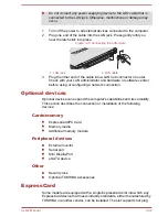
Page 79: ...are or software vendor before using or configuring a network connection Optional devices Optional devices can expand the computer s capabilities and its versatility This section describes the connection or installation of the following devices Cards memory ExpressCard PC Card Memory media Additional memory module Peripheral devices External monitor Serial port Mini DisplayPort eSATA device Other S...

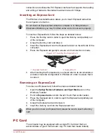
Page 80: ... ensure a firm connection is made Figure 3 11 Inserting the ExpressCard 1 2 1 ExpressCard slot 2 ExpressCard 5 After inserting the ExpressCard you should refer to its documentation and also check the configuration in Windows in order to ensure that it is correct Removing an ExpressCard To remove an ExpressCard follow the steps as detailed below 1 Open the Safely Remove Hardware and Eject Media ico...

Page 81: ...turned on Do not insert a PC Card while the computer is in Sleep Mode or Hibernation Mode as you may find that some cards do not work properly To insert a PC Card follow the steps as detailed below 1 Insert the PC Card into the PC Card slot on the left side of the computer 2 Press the PC Card gently to ensure a firm connection is made Figure 3 12 Inserting the PC Card 1 2 1 PC Card slot 2 PC Card ...

Page 82: ... such as digital cameras and Personal Digital Assistants Keep foreign objects out of the memory media slot Never allow metal objects such as screws staples and paper clips to enter the computer or Keyboard Foreign metal objects can create a short circuit which can cause computer damage and fire possibly resulting in serious injury Please note that an adaptor is required to use miniSD microSD Card ...

Page 83: ...different so pay careful attention to the logo when purchasing The SD memory card logo is The SDHC memory card logo is The SDXC memory card logo is TM The maximum capacity of SD memory cards is 2GB The maximum capacity of SDHC memory cards is 32GB The maximum capacity of SDXC memory cards is 64GB Card Type Capacities SD 8MB 16MB 32MB 64MB 128MB 256MB 512MB 1GB 2GB SDHC 4GB 8GB 16GB 32GB SDXC 64GB ...

Page 84: ...h to the lock position if you do not want to record data Memory cards have a limited lifespan so it is important to backup important data Do not write to a card if the battery power is low Low power could affect writing accuracy Do not remove a card while read write is in progress For more details on using memory cards see manuals accompanying the cards About the write protect The memory media car...

Page 85: ...rted media devices To remove a memory media follow the steps as detailed below 1 Open the Safely Remove Hardware and Eject Media icon on the Windows Taskbar 2 Point to memory media and click the left Touch Pad control button 3 Press the memory media to partially extend it out of the computer 4 Grasp the media and remove it Make sure the Memory Media slot indicator is out before you remove the memo...

Page 86: ... the following conditions a The computer is turned on b The computer was shut down in either Sleep or Hibernation Mode c Wake up on LAN is enabled d The wireless communication function is on e Sleep and Charge function is enabled Be careful not to let screws or other foreign matter fall into the computer It could cause malfunction or electric shock Additional memory module is a precision electroni...

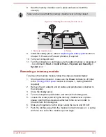
Page 87: ...ery pack section in Chapter 5 Power and Power Up Modes if required 5 Loosen the screw s securing the memory module cover in place please note that the screw s are attached to the cover in order to prevent them from being lost 6 Slide your fingernail or a thin object under the cover and lift it off Figure 3 15 Removing the memory module cover 1 2 1 Screw 2 Memory module cover User s Manual 3 40 ...

Page 88: ... in serious injury Do not touch the connectors on the memory module or on the computer Debris on the connectors may cause memory access problems The slot A is reserved for the first memory module Use the slot B for expanded memory If only one module is installed use the slot A Align the grooves along the edges of the memory module with the locking tabs on the connector and insert the module into t...

Page 89: ... the memory module follow the steps as detailed below 1 Shut down the computer make sure the Power indicator is off refer to the Turning off the power section in Chapter 1 Getting Started if required 2 Remove the AC adaptor and all cables and peripherals connected to the computer 3 Close the display panel 4 Turn the computer upside down and remove the battery pack 5 Loosen the screw s securing the...

Page 90: ...r Debris on the connectors may cause memory access problems Figure 3 18 Removing the memory module 1 1 1 Latches 9 Seat the memory module cover in place and secure it with the screw s Take care to ensure that the memory module cover is firmly closed 10 Install the battery pack 11 Turn your computer over External monitor An external analog monitor can be connected to the External RGB monitor port o...

Page 91: ...he The Keyboard section for further details on using hot keys to change the display setting When displaying desktop at external analog monitor desktop is sometimes displayed on the center of the monitor with black bars around desktop with small size At that time please read the manual of the monitor and set the display mode which is supporting at the monitor Then it will be displayed with suitable...

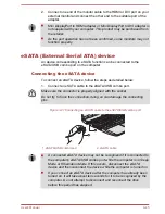
Page 92: ... 1 Connect an eSATA cable to the eSATA USB combo port Make sure the connector is properly aligned with the socket Do not try to force the connection doing so can damage the connecting pins Figure 3 21 Connecting an eSATA cable to the eSATA USB combo port 1 2 1 eSATA USB combo port 2 eSATA cable A connected eSATA device may not be recognized if it is connected to the computer s eSATA USB combo port...

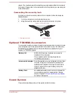
Page 93: ...ve Serial port The serial connector can be used to connect to RS 232C compatible devices RS 232C compatible devices include the following Modem Mouse Printer Some models are equipped with a serial port To connect a serial port follow the steps as detailed below 1 Turn the computer s power off 2 Connect the serial connector to the serial port and tighten the screws on the left and right hand side F...

Page 94: ...r even more powerful and convenient to use For reference the following list details some of the items that are available from your reseller or TOSHIBA dealer Memory Kit DDR3 1600 memory modules can easily be installed in the computer The available option memory depends on TOSHIBA authorization Universal AC Adaptor If you frequently use your computer at more than one site it may be convenient to pu...

Page 95: ...s inadequate move the Microphone Boost slider to a higher level Audio Enhancements In order to apply the sound effects for your current speaker follow the steps below 1 Right click on the Speakers icon on the Taskbar and select Playback devices from the sub menu 2 Select Speakers and click Properties 3 On the Enhancements tab select the sound effects you would like and click Apply Realtek HD Audio...

Page 96: ...onalization Display Change display settings If you are running some applications for example a 3D application or video playback and so on you may see some disturbance flickering or frame dropping on your screen If that occurs adjust the resolution of display lowering it until the screen is displayed properly Disabling Windows Aero may also help correct this issue Computer Handling This section exp...

Page 97: ...disconnect the AC adaptor and allow it to cool down a failure to follow this instruction may result in minor heat injury Be careful not to subject the computer to impact or shock a failure to follow this instruction could result in damage to computer computer failure or loss of data Never transport your computer with any cards installed this may cause damage to either the computer and or the card ...

Page 98: ...off and the processor operation returned to its standard speed If the processor s temperature reaches an unacceptably high level with either setting the computer automatically shuts down to prevent any damage In this instance all unsaved data in memory will be lost User s Manual 3 51 ...

Page 99: ...uilt in HDD SSD supports Hi Speed Start Mode When system needs to be restarted because of Windows update drivers update or applications installation please Shut down or Restart accordingly If not those changes will not be reflected to the system properly with Hi Speed Start Mode When setting password e g user password HDD password please enter it using keyboard When the system is booting in Hi Spe...

Page 100: ...application from the button can be changed TOSHIBA PC Diagnostic Tool The TOSHIBA PC Diagnostic Tool will display basic system configuration information and allow the functionality of some of the computer s built in hardware devices to be tested TOSHIBA Password Utility The TOSHIBA Password utility allows you to set a password in order to restrict access to the computer TOSHIBA Flash Cards The TOS...

Page 101: ...do not have a fingerprint module installed TOSHIBA Face Recognition TOSHIBA Face Recognition uses a face verification library to verify the face data of users when they log in to Windows If the verification is successful the user will be logged into Windows automatically The user can thus avoid having to enter a password or the like which makes the login process easier For more information please ...

Page 102: ...ightly lowers performance of some devices to reduce electric power consumption You can realize measurable power savings by using it continuously TOSHIBA eco Utility helps you monitor your power savings by showing approximate real time power consumption Furthermore it shows approximate accumulated power consumption and approximate accumulated power savings when using eco mode daily weekly and month...

Page 103: ...tion which will be treated in strict accordance with the rules and regulations as well as applicable data protection law To access this utility click Start All Programs TOSHIBA Support Recovery Service Station TOSHIBA Sleep Utility This utility is able to either enable or disable the Sleep and Charge function Sleep and Charge By connecting to the USB port devices such as digital audio players are ...

Page 104: ...usic pictures and videos by streaming content to any compatible device in your home To access this utility click Start All Programs TOSHIBA Media Entertainment TOSHIBA Media Controller For more information please refer to the TOSHIBA Media Controller Help TOSHIBA Resolution Plug in for Windows Media Player The plug in lets you upconverts wmv and mp4 videos on Windows Media Player For more informat...

Page 105: ...nel System and Security Power Options eco button Press this button to launch the TOSHIBA eco Utility This button changes On and Off of eco Mode TOSHIBA Presentation button The TOSHIBA Presentation button has the same functionality as the Connect display button in the Mobility Center Hot keys Hot keys are specific key combinations that let you quickly change the system configuration directly from t...

Page 106: ...y capacity and protects electronic components from abnormal conditions such as a voltage overload from the AC adaptor This can be specified in the Power Options Battery save mode 1 This feature lets you configure the computer in order to save battery power This can be specified in the Power Options Panel power on off 1 This feature automatically turns power to the computer off when the display pan...

Page 107: ...ting from your software Data is maintained in the computer s main memory so that when you next turn on the power you can continue working right where you left off USB Wakeup function This function restores the computer from Sleep Mode depending on the external devices connected to the USB ports For example if a mouse or USB keyboard is connected to a USB port clicking the mouse button or pressing ...

Page 108: ...ications of the external devices please contact the device manufacturer or check the specifications of the external devices thoroughly before use Using the sleep and charge function to charge external devices will take longer than charging the devices with their own chargers If Sleep and Charge function is enabled the computer s battery will discharge during hibernation or when the computer is tur...

Page 109: ...A Mode for your USB device to charge Do not use 2 0A Mode when your USB devices do not support high current mode 2 0A Mode This function may not be able to be used with some connected external devices even if the appropriate mode is selected In this situation clear the Enable Sleep and Charge check box and stop using this function While using 2 0A Mode your computer can supply USB bus power DC5V 2...

Page 110: ...correctly In that case log in using your Windows password If recognition of a registrant fails repeatedly refer to your computer documentation to learn ways to improve recognition performance TOSHIBA Face Recognition records face data in a log when face recognition fails When transferring ownership or disposing of your computer please uninstall the application or delete all the logs created by the...

Page 111: ...start the guide Please follow the guide to practice Click the Back button to practice the guide once more 4 Click the Next button to start image capturing process Adjust the position of your face so that it fits within the face shaped frame 5 Once your face has been positioned properly the recording will commence Start moving your neck very slightly to the left and right and then move your neck up...

Page 112: ...file For further information on this utility please refer to help file To launch the help file click on the Help button in the Management screen Windows Logon via TOSHIBA Face Recognition This section explains how to login to Windows with TOSHIBA Face Recognition Two authentication modes are provided 1 N Mode Login screen If the face authentication tile is selected by default you can log in withou...

Page 113: ...hentication was successful but an authentication error subsequently occurred during the login to Windows you will be asked to provide your account information TOSHIBA Password Utility The TOSHIBA Password Utility provides two levels of password security User and Supervisor Passwords set by the TOSHIBA Password Utility function are different from the Windows password User Password To start the util...

Page 114: ...BIOS Setup Press and hold the F2 key and then turn on the computer the BIOS setup utility will load To end the BIOS Setup Press F10 and then press Y to accept the changes The computer will restart Change button Click this button to change a registered password Before you can change a password you must first enter the current password correctly Please use BIOS Setup to change or delete the HDD Pass...

Page 115: ...on the sensor if you have already registered the fingerprint with the Fingerprint utility and enabled Fingerprint System Pre Boot Authentication If you would not like to swipe your finger or cannot authenticate the fingerprint for some reasons push the BACK SPACE key to skip the fingerprint authentication screen You can try to swipe the fingerprint up to five times If you failed fingerprint authen...

Page 116: ...er immediately to apply these changes Accessing HW Setup To run the HW Setup program click Start All Programs TOSHIBA Tools Utilities HWSetup HW Setup window The HW Setup window contains a number of tabs General Display CPU Boot Setting Keyboard LAN SATA USB and Advanced to allow specific functions of the computer to be configured In addition there are also three buttons OK Cancel and Apply OK Acc...

Page 117: ...des associated with the processor the following settings are available Dynamically Switchable The processor s automatic clock speed switching function is enabled in use the processor s operation is automatically switched when necessary default Always High The processor s automatic clock speed switching function is disabled in use the processor will always run at its highest level of power consumpt...

Page 118: ...ive default With this setting the USB memory device can be used to start the computer as though it were a hard disk drive based on the hard disk drive settings within both the Boot Priority and HDD Priority options detailed previously FDD Sets the USB memory to be the equivalent of a floppy diskette drive With this setting the USB memory device can be used to start the computer as though it were a...

Page 119: ...mputer check box within the LAN Device properties This feature does not effect the Wake up on LAN from sleep or hibernation Power will be automatically turned on when a signal is received from an administrator s computer which is connected via a network The following settings can be changed when the Built in LAN is Enabled Connect the AC adaptor when using the Wake up on LAN function The battery r...

Page 120: ...ed your computer can supply USB bus power DC5V 1 5A to the compatible ports while the computer is turned on The System ON CDP Charge Mode may not work with certain external devices even if they are compliant with the USB specifications In those cases use a USB port without USB Sleep and Charge function or disable System ON CDP Charge Mode It is recommended that AC adaptor be connected to the compu...

Page 121: ... system functions such as power consumption battery health and the system cooling informing you of significant system conditions This application recognizes the system and individual component serial numbers and will track specific activities related to the computer and their usage The collected information includes device operation time and number of actuations or status changes i e number of pow...

Page 122: ...an be started using the following methods Click Start All Programs TOSHIBA Support Recovery PC Health Monitor Click the icon in the notification area then click the Enable PC Health Monitor message the first time you run the application and Run PC Health Monitor every time thereafter No matter which method is used the TOSHIBA PC Health Monitor explanation screen will be displayed Clicking Next wil...

Page 123: ...ery pack refer to the Replacing the battery pack section in chapter 5 Power and Power Up Modes if required 5 Using a thin tipped tool push on the hole in the edge of the Cooling module cover and slide it in the direction of the arrow to remove Figure 4 1 Removing the cooling module cover 1 2 1 2 1 Hole 2 Cooling module cover 6 Lift the plastic film and clean the cooling module using a vacuum clean...

Page 124: ...ack might be temporarily interrupted TOSHIBA HDD Protection cannot be used in models that are equipped with SSD When vibration is detected a message will be displayed on the screen and the icon in the Taskbar notification area will change to the protection state This message is displayed until the OK button is pressed or 30 seconds pass When vibration subsides the icon returns to the normal state ...

Page 125: ...ction mode 3D Viewer This feature displays a 3D object on the screen which moves in according to tilting or vibration of the computer When the TOSHIBA HDD Protection detects computer vibration the Hard Disk Drive head is parked and the 3D object disk rotation will stop When the head is un parked the disk will begin to rotate again The 3D Viewer can be started from the icon in the task tray This 3D...

Page 126: ... software from the Recovery hard disk drive System Recovery Options The System Recovery Options feature is installed on the hard disk when shipped from the factory The System Recovery Options menu includes tools to repair startup problems run diagnostics or restore the system See the Windows Help and Support content for more information about Startup Repair The System Recovery Options can also be ...

Page 127: ...is stored on the hard disk drive and can be copied to either DVD or USB Flash Memory by using the following steps 1 Select either blank disc or USB Flash Memory The application will allow you to choose from a variety of different media onto which the recovery image can be copied including disc media and USB Flash Memory Please note that some of the above media may not be compatible with the optica...

Page 128: ...er 3 While holding down F12 key on the keyboard turn on your computer when the TOSHIBA Leading Innovation logo screen appears release the F12 key 4 Use the up and down cursor key to select the appropriate option from the menu according to your actual recovery media Please refer to the Boot Setting section for further information 5 A menu will be displayed from which you should follow the on screen...

Page 129: ...the partitions on your hard disk drive you may find that it becomes impossible to setup your computer When the sound mute feature has been activated by pressing the FN ESC key be sure to disable this to allow sounds to be heard before starting the restore process Please refer to The Keyboard in Chapter 3 Operating Basics for further details You can not use System Recovery Options if restoring the ...

Page 130: ...attery charge status are affected by different power conditions including whether an AC adaptor is connected whether a battery pack is installed and what the charge level is for that battery Power on Power off no operation AC adaptor connected Battery fully charged Operates No charge LED Battery green DC IN green No charge LED Battery green DC IN green Battery partially charged or no charge Operat...

Page 131: ...ble the Battery DC IN and Power indicators on the system indicator panel alert you to the computer s operating capability and battery charge status Battery indicator Check the Battery indicator to determine the status of the battery pack The following indicator lights indicate the battery status Flashing orange The battery charge is low the AC adaptor must be connected in order to recharge the bat...

Page 132: ...her conditions the indicator does not light Power indicator Check the Power indicator to determine the power status of the computer the following indicator conditions should be noted Green Indicates power is being supplied to the computer and the computer is turned on Blinking orange Indicates that the computer is in Sleep Mode and that there is sufficient power available AC adaptor or battery to ...

Page 133: ...to Chapter 6 Troubleshooting for further information The RTC battery does not charge while the computer is turned off even if the AC adaptor is attached Care and use of the battery pack This section provides the important safety precautions in order to handle your battery pack properly Refer to the enclosed Instruction Manual for Safety and Comfort for detailed precautions and handling instruction...

Page 134: ...cator flashes the computer will enable Hibernation Mode so that you do not lose any data and automatically turn itself off You must recharge a battery pack when it becomes discharged Procedures To recharge a battery pack while it is installed in the computer connect the AC adaptor to the DC IN 15V jack and plug the other end into a working outlet the Battery indicator will glow orange while the ba...

Page 135: ...attery capacity Remaining battery power can be monitored using the following methods Clicking the battery icon on the Taskbar Via the Battery Status in the Windows Mobility Center window You should wait at least 16 seconds after turning on the computer before trying to monitor the remaining operating time This is because the computer needs this time to check the battery s remaining capacity and th...

Page 136: ...e a month disconnect the computer from a power source and operate it on battery power until the battery pack fully discharges Before doing so follow the steps as detailed below 1 Turn off the computer s power 2 Disconnect the AC adaptor and turn on the computer s power if it does not turn on then go to Step 4 3 Operate the computer on battery power for five minutes If you find that the battery pac...

Page 137: ...teps Do not remove the battery pack while the computer is in Sleep Mode Data is stored in RAM so if the computer loses power it could be lost In Hibernation Mode data will be lost if you remove the battery pack or disconnect the AC adaptor before the save is completed Wait for the Hard Disk Drive Optical Disc Drive eSATA indicator to go out Do not touch the battery release latch while holding the ...

Page 138: ...modes The computer has three different power up modes as follows Shut Down Mode The computer will shut down without saving data in view of this you must always save your work before you turn the computer off Hibernation Mode Data in memory will be saved to the hard disk drive Sleep Mode Data will be maintained in the computer s memory Please refer to the sections Turning on the power and Turning o...

Page 139: ...e not for Shut Down Mode If the panel power off function is enabled and you manually shut down Windows do not close the display panel until the shut down process has been completed System automatic Sleep Hibernation This feature automatically turns off the system in Sleep or Hibernation Mode if the computer is not used for a set duration Refer to Special features in Chapter 4 for an explanation of...

Page 140: ...d in this chapter are meant only as a guide they are not definitive problem solving techniques In reality many problems can be solved simply but a few may require help from TOSHIBA Support if you find you need to consult others be prepared to describe the problem in as much detail as possible Preliminary checklist You should always consider the simplest solution first the items detailed in this ch...

Page 141: ...random characters Make a screenshot of the current display and if possible look up the messages in the documentation included with the computer software or operating system Check that all connecting cables are correctly and firmly attached as loose cables can cause erroneous or intermittent signals Do any indicators light if so which ones what color are they and do they stay on or blink Write down...

Page 142: ...aneously once then click Start Task Manager The Windows Task Manager window appears 2 Click the Applications tab If a program has stopped responding the words not responding appear beside its name in the list 3 Select the program you want to close then click End Task Closing the failed program should allow you to continue working If it does not continue with the next step 4 Close the remaining pro...

Page 143: ...Clock RTC battery all of which are interrelated with any one having the ability to produce apparent power problems Overheating power down If the processor s temperature reaches an unacceptably high level with either setting the computer will automatically shuts down to prevent any damage in this instance all unsaved data in memory will be lost Problem Procedure Computer shuts down and DC IN indica...

Page 144: ...e computer and a working power outlet Check the condition of the cord and terminals If the cord is frayed or damaged it should be replaced while if the terminals are soiled they should be cleaned with a clean cotton cloth If the AC adaptor still does not power the computer you should contact TOSHIBA Support Battery If you suspect a problem with the battery you should check the status of the DC IN ...

Page 145: ...ct the AC adaptor and replace the battery taking care to ensure that it is securely seated in the computer Check the Battery indicator if it does not glow allow the computer to charge the battery for at least twenty minutes If the Battery indicator starts to glow after this period allow the battery to continue to charge for at least another twenty minutes before turning on the computer However if ...

Page 146: ... will end and the computer will restart Keyboard Keyboard problems can be caused by the setup and configuration of the computer please refer to the section The Keyboard in Chapter 3 Operating Basics for further information Problem Procedure Some letter keys produce numbers Check that the numeric keypad overlay is not activated press the FN F11 hot key and try typing again Output to screen is garbl...

Page 147: ...her there is a disc in the optical disc drive if so remove it and try to start the computer again If this has no effect check the Boot Priority setting within the TOSHIBA HW Setup utility please refer to the Boot Setting section in Chapter 4 Utilities Advanced Usage for further information Slow performance The files on the hard disk drive may be fragmented in this instance you should run the disk ...

Page 148: ... For further information please refer to Chapter 3 Operating Basics Problem Procedure Memory media card error occurs Remove the memory media card from the computer and then reinsert it in order to ensure it is firmly connected If the problem persists then you should refer to the documentation supplied with your memory media card for further information You cannot write to a memory media card Remov...

Page 149: ... mouse section in this chapter and the documentation supplied with your mouse Touch Pad Problem Procedure The Touch Pad does not work Check the Device Select settings Click Start Control Panel Hardware and Sound Mouse Pressing FN F9 to enables On screen pointer does not respond to pointing device operation In this instance the system might be busy Try moving the mouse again after waiting a short w...

Page 150: ...nce the system might be busy Try moving the mouse again after waiting a short while Remove the mouse from the computer and then reconnect it to a free USB port in order to ensure it is firmly attached Double clicking does not work In this instance you should initially try changing the double click speed setting within the Mouse Control utility 1 To access this utility click Start Control Panel Har...

Page 151: ... another enrolled finger The fingerprint sensor compares and analyzes the unique characteristics in a fingerprint However there may be instances where certain users are unable to register their fingerprints due to insufficient unique characteristics in their fingerprints The recognition success rate may differ from user to user The fingerprint cannot be read due to injuries to the finger In this i...

Page 152: ... function When there is a current overflow of the external device connected to the compatible port USB bus power DC5V supply may be stopped for safety reasons When this happens disconnect an external device if some external devices are connected After that turn the power of the computer ON OFF to restore the function If this function can not be still used even if only one external device is connec...

Page 153: ...fter turning the computer ON If the external device still does not work connect device to an USB port that does not have the Sleep and Charge function compatible icon or change to disable the Sleep and Charge function The USB Wakeup function does not work When System ON CDP Charge Mode or USB Sleep and Charge function is enabled the USB WakeUp function does not work for ports that support the Slee...

Page 154: ...rs are properly installed to achieve this you should refer to both the device documentation and the operating system documentation If you are still unable to resolve the problem contact TOSHIBA Support Additional memory module Please also refer to Chapter 3 Operating Basics for further information on installing and removing memory modules Problem Procedure An error will occur if a memory module is...

Page 155: ...either the internal microphone or an external microphone connected to the computer please refer to Sound System in Chapter 3 Operating Basics for further information Volume cannot be adjusted during Windows start up or shut down If you are still unable to resolve the problem contact TOSHIBA Support External monitor Please also refer to Chapter 3 Operating Basics and to the documentation supplied w...

Page 156: ...l monitor are set to clone mode and they are turned off by the timer the display panel or the external monitor may not display when turned on again If this occurs press FN F5 to re set the display panel and external monitor to clone mode Display error occurs Check that the cable connecting the external monitor to the computer is firmly attached If you are still unable to resolve the problem contac...

Page 157: ...ta you should ensure that the parity bit and stop bit settings correspond with those of the remote computer you should check the flow control and communication protocol settings within your communication application You cannot receive an incoming call Ensure that the communication application s rings before auto answer feature is set correctly If you are still unable to resolve the problem contact...

Page 158: ... access Bluetooth device Check to ensure the computer s Wireless Communication function is on Check to ensure the Bluetooth Manager application is running on the computer and that power to the external Bluetooth device is turned on Check to ensure that no optional Bluetooth Adaptor is installed in the computer the built in Bluetooth hardware cannot operate simultaneously with another Bluetooth con...

Page 159: ...enu If you have not created Recovery Media please contact TOSHIBA support for assistance TOSHIBA support If you require any additional help using your computer or if you are having problems operating the computer you may need to contact TOSHIBA for additional technical assistance Before you call Some problems you experience may be related to software or the operating system so it is important that...

Page 160: ...TOSHIBA technical support If you are still unable to solve the problem and suspect that it is hardware related visit TOSHIBA technical support website http www toshiba co jp worldwide User s Manual 6 21 ...

Page 161: ...at extend beyond the main body Environmental Requirements Conditions Ambient temperature Relative humidity Operating 5 C 41 F to 35 C 95 F 20 to 80 noncondensing Non operating 20 C 4 F to 60 C 140 F 10 to 90 noncondensing Wet bulb temperature 29 C maximum Conditions Altitude from sea level Operating 60 to 3 000 meters Non operating 60 to 10 000 meters maximum Power Requirements AC adaptor 100 240V...

Page 162: ...y Type of dialing Pulse Tone Control command AT commands EIA 578 commands Monitor function Computer s speaker Communication specifications Communication system Data Full duplex Fax Half duplex Communication protocol Data ITU T Rec Former CCITT V 21 V 22 V 22bis V 32 V 32bis V 34 V 90 Bell 103 212A Fax ITU T Rec Former CCITT V 17 V 29 V 27ter V 21 ch2 User s Manual A 2 ...

Page 163: ...9333 30666 32000 33333 34666 360 00 37333 38666 40000 41333 42666 44000 4 5333 46666 48000 49333 50666 52000 5333 3 54666 560003223 3233 and 3220 bps Fax 2400 4800 7200 9600 12000 14400 bps Transmitting level 10 dBm Receiving level 10 to 40 dBm Input output impedance 600 ohms 30 Error correcting MNP class 4 and ITU T V 42 Data compression MNP class 5 and ITU T V 42bis Power supply 3 3V supplied by...

Page 164: ... S and Canada UL listed and CSA certified No 18 AWG Type SVT or SPT 2 Australia AS Japan DENANHO Europe Austria OVE Italy IMQ Belgium CEBEC The Netherlands KEMA Denmark DEMKO Norway NEMKO Finland FIMKO Sweden SEMKO France LCIE Switzerland SEV Germany VDE United Kingdom BSI In Europe two conductors power cord must be VDE type H05VVH2 F or H03VVH2 F and for three conductors power cord must be VDE ty...

Page 165: ...ectrical Code Part II The following illustrations show the plug shapes for the U S A and Canada the United Kingdom Australia Europe and China USA UL approved United Kingdom BS approved Australia AS approved Europe Approved by the appropriate agency Canada CSA approved China CCC approved User s Manual B 2 ...

Page 166: ...such as high end computer aided design applications use of several applications or functionalities simultaneously use of computer in areas with low air pressure high altitude 1 000 meters or 3 280 feet above sea level use of computer at temperatures outside the range of 5 C to 30 C 41 F to 86 F or 25 C 77 F at high altitude all temperature references are approximate and may vary depending on the s...

Page 167: ...nfigured with more than 3GB memory the memory might be displayed as approximately 3GB only depending on the computer s hardware specifications This is correct because the operating system usually displays the available memory instead of the physical memory RAM built into the computer Various system components like the video adapter s GPU and PCI devices like Wireless LAN etc require their own memo...

Page 168: ...on the usage of the computer the brightness of the LCD screen will deteriorate This is an intrinsic characteristic of LCD technology Maximum brightness is only available when operating in AC power mode Screen will dim when the computer is operated on battery power and you may not be able to increase the brightness of the screen Graphics Processing Unit GPU Graphics Processing Unit GPU performance ...

Page 169: ...Copy Protection Applicable copy protection standards included in certain media may prevent or limit recording or viewing of the media User s Manual C 4 ...

Page 170: ... compliant to Bluetooth Specification depending on the model you purchased as defined and approved by the Bluetooth Special Interest Group Logo certification with Bluetooth wireless technology as defined by the Bluetooth Special interest Group Please note that it is not possible to confirm the operation of all functions of all Bluetooth devices that are available In view of this it may be noted th...

Page 171: ...lect the consensus of the scientific community and result from deliberations of panels and committees of scientists who continually review and interpret the extensive research literature In some situations or environments the use of Wireless products may be restricted by the proprietor of the building or responsible representatives of the organization These situations may for example include Using...

Page 172: ... own premises For public use a general authorization is required Luxembourg Implemented General authorization required for network and service supply Norway Implemented This subsection does not apply for the geographical area within a radius of 20 km from the centre of Ny Alesund Russian Federation Only for indoor applications Restrictions for Use of 5150 5350MHz Frequencies in Europe Italy For pr...

Page 173: ...e used outside own premises Luxembourg Implemented General authorization required for network and service supply Russian Federation Limited e i r p 100mW Permitted to use only for indoor applications closed industrial and warehouse areas and on board aircraft 1 Permitted to use for local networks of aircraft crew service communications on board aircraft in area of the airport and at all stages of ...

Page 174: ...the detailed information Caution Exposure to Radio Frequency Radiation The radiated output power of the Wireless device is far below the FCC radio frequency exposure limits Nevertheless the Wireless device shall be used in such a manner that the potential for human contact during normal operation is minimized In the usual operating configuration the distance between the antenna and the user should...

Page 175: ...ion 1 Important notice The frequency bandwidth of this equipment may operate within the same range as industrial devices scientific devices medical devices microwave ovens licensed radio stations and non licensed specified low power radio stations for mobile object identification systems RFID used in factory production lines Other Radio Stations 1 Before using this equipment ensure that it does no...

Page 176: ...400 MHz to 2 483 5 MHz It is impossible to avoid the band of mobile object identification systems 4 About the JEITA 5GHz Wireless LAN supports W52 W53 W56 Channel Device Authorization This device obtains the Technical Regulation Conformity Certification and it belongs to the device class of radio equipment of low power data communication system radio station stipulated in the Telecommunications Bu...

Page 177: ...ino Wireless N 6205 a b g n a b g Atheros AR938x Wireless Network Adapter a b g n a b g Intel Centrino Advanced N 6235 a b g n a b g Atheros AR9485WB EG Wireless Network Adapter This equipment is approved to the radio standard by the countries regions in the following table Do not use this equipment in the countries regions which are not listed in the table below As of April 2012 Austria Belgium B...

Page 178: ...User s Manual D 9 ...

Page 179: ...hiba 4 3 problems 6 19 Boot Priority 4 19 C Cleaning the computer 3 49 Cooling vents 2 3 D DC IN indicator 2 2 DC IN indicator 5 3 Display automatic power off 4 7 hinges 2 10 opening 1 4 screen 2 9 Display controller 2 12 Documentation list 1 1 Dual Pointing Device Touch Pad control buttons 3 1 E Equipment checklist 1 1 eSATA device problems ExpressCard inserting 3 33 removing 3 33 External monito...

Page 180: ...power off 4 7 HDD Protection 4 26 Heat dispersal 3 50 4 8 Hibernation Mode 1 9 4 9 Hot keys 4 7 HW Setup accessing 4 18 Boot 4 19 display 4 19 general 4 18 keyboard 4 20 LAN 4 21 SATA 4 23 USB 4 22 window 4 18 K Keyboard FN Sticky key 3 6 Function keys F1 F12 3 3 Hot key functions 3 4 problems 6 7 Windows special keys 3 6 Keypad overlay Arrow mode 3 7 Numeric mode 3 7 temporarily using normal keyb...

Page 181: ...ing Device Touch Pad 2 11 6 10 Power conditions 5 1 Hibernation Mode 1 9 panel on off 4 8 5 10 Shut Down mode Boot Mode 1 6 Sleep Mode 1 7 System Auto Off 5 10 turning off 1 6 turning on 1 5 Problems AC power 6 5 Additional memory module 6 15 Analyzing the problem 6 2 Battery 6 5 Bluetooth 6 19 eSATA device 6 14 External monitor 6 16 Fingerprint Sensor 6 12 Hard disc drive 6 8 6 9 Hardware and sys...

Page 182: ... Mode setting 1 7 System automatic 4 8 Soft keys ENTER 3 4 ScrLock 3 4 Sound system problems 6 15 T TOSHIBA Assist 4 4 TOSHIBA ConfigFree 4 4 TOSHIBA Disc Creator 3 20 4 4 TOSHIBA DVD RAM Utility 4 5 TOSHIBA HDD SSD Alert Utility 4 5 TOSHIBA PC Diagnostic Tool 4 2 U USB device problems 6 12 V Video mode 3 49 Video RAM 2 12 W Web Camera 2 9 Wireless communication indicator 2 2 Wireless LAN problems...

Page 183: ...T cathode ray tube DC direct current DDR double data rate DIMM dual inline memory module DVD digital versatile disc DVD R Digital Versatile Disc Recordable DVD RAM Digital Versatile Disc Random Access Memory DVD R DL Digital Versatile Disc Recordable Dual Layer DVD ROM Digital Versatile Disc Read Only Memory DVD RW Digital Versatile Disc ReWritable DVD R DL Digital Versatile Disc Recordable Double...

Page 184: ...e Digital SDHC Secure Digital High Capacity SDXC Secure Digital Extended Capacity SDRAM synchronous dynamic random access memory SLI Scalable Link Interface SSD Solid state drive TFT thin film transistor USB Universal Serial Bus UXGA ultra extended graphics array VGA video graphics array WAN wide area network WSXGA wide super extended graphics array WSXGA wide super extended graphics array plus WU...

Reviews: