4 Replacement Procedures
Error! Style not defined.
Error! Style not defined.
Satellite L450/Pro L450/L450D/Pro L450D Maintenance Manual
4-4
Before You Begin
Before you begin to disassemble the laptop, keep in mind the precautions and advice in this
section. Always begin disassembly by removing the AC adapter and battery pack. Remove the
optional parts and accessories as well. The procedures for removing the batteries will be
explained later.
Disassemble the laptop only when an abnormality has occurred.
Use only the recommended tools.
To run and store the laptop, be sure to prepare a working environment that is free from:
Dust and contaminants
Static electricity
Extremely high or low temperatures and extremely high humidity
Run the diagnostic tests explained in Chapter 2 of this manual to identify the FRU that has
probably caused the system failure.
Perform only the required machine operations. Use only the disassembly and reinstallation
procedures described in this manual.
Place the removed components in a safe place away from the laptop so that they are not damaged
or get in the way of you doing your work.
Normally, a number of screws need to be removed or replaced during disassembling. Place the
removed screws in a safe place so that you can easily find the right screws for the right
components.
When assembling the laptop, use the specified screws to fasten the parts to the specified
locations. See the appropriate explanations and figures for screw sizes.
To avoid personal injury, use care to handle components that have sharp edges or corners.
After you have replaced a FRU, check that the FRU works correctly to ensure normal laptop
operation.
Summary of Contents for Satellite L450 series
Page 1: ...Toshiba Personal Computer Satellite Maintenance Manual TOSHIBA CORPORATION CONFIDENTIAL ...
Page 14: ...Chapter 1 Hardware Overview ...
Page 17: ......
Page 33: ...Chapter 2 Troubleshooting Procedures 2 ...
Page 34: ......
Page 82: ...3 Tests and Diagnostics 1 Chapter 3 Tests and Diagnostics ...
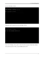
Page 98: ...3 Tests and Diagnostics 17 Memory Write Test Memory Read Write Test ...
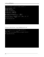
Page 104: ...3 Tests and Diagnostics 23 2 If the Magnetic switch test pass it will show below display ...
Page 119: ...3 Tests and Diagnostics 38 If the picture shows as below it means he HDD function is NG ...
Page 123: ...Chapter 4 Replacement Procedures ...
Page 209: ...3 Thai TI Keyboard Figure TI keyboard 4 Korean KO Keyboard Figure KO keyboard ...
Page 211: ...7 Hebrew HB Keyboard Figure HB keyboard 8 Danish DM Keyboard Figure DM keyboard ...
Page 212: ...9 Swiss SW Keyboard Figure SW keyboard 10 Arabic ARE Keyboard Figure ARE keyboard ...
Page 213: ...11 Czech CZ Keyboard Figure CZ keyboard 12 Russian RU Keyboard Figure RU keyboard ...
Page 214: ...13 Portuguese PO Keyboard Figure PO keyboard 14 Slovakian SL Keyboard Figure SL keyboard ...
Page 215: ...15 Italian IT Keyboard Figure IT keyboard 16 French FR Keyboard Figure FR keyboard ...
Page 216: ...17 German GR Keyboard Figure GR keyboard 18 Greek GK Keyboard Figure GK keyboard ...
Page 217: ...19 Canada French CF Keyboard Figure CF keyboard 20 Hungarian HG Keyboard Figure HG keyboard ...
Page 218: ...21 Spanish SP Keyboard Figure SP keyboard 22 Turkish TR Keyboard Figure TR keyboard ...
Page 219: ...3 Turkish F TF F Keyboard Figure TF F keyboard 24 Swedish SD Keyboard Figure SD keyboard ...
Page 220: ...25 Belgian BE Keyboard Figure BE keyboard 26 Yugoslavian YU Keyboard Figure YU keyboard ...
Page 221: ...27 Norwegian NW Keyboard Figure NW keyboard 28 Scandinavian ND Keyboard Figure ND keyboard ...
Page 223: ...31 Japanese JP Keyboard Figure JP keyboard 32 Romania RO Keyboard Figure RO keyboard ...

