– 12 –
7
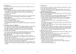
ELECTRIC WORK
WARNING
1. Using the specified wires, ensure to connect the wires, and fix wires securely so that
the external strength of the wires do not transmit to the connecting part of the
terminals.
Incomplete connection or fixation may cause fire, etc.
2. For electric work, strictly follow to the Local Regulation in each country and the
Installation Manual, and use an exclusive circuit.
Capacity shortage of power circuit or incomplete installation may cause an electric shock or fire.
REQUIREMENT
• Perform the electric wiring so that it does not come to contact with the high-temperature part of the pipe. The coating
may melt resulted in an accident.
• After connecting wires to the terminal blocks, provide a trap and fix wires with the wire clamp.
• Store the refrigerant piping line and control wiring line in the same line.
• Do not turn on the power of the indoor unit until vacuuming of the refrigerant pipes completes.
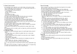
Wire connections
REQUIREMENT
• Check that power is not supplied to the indoor unit before connecting wires.
• Be sure to put wires through the wire connecting ports on the PMV Kit and the indoor unit.
• If a PMV connector cannot be connected to the P.C. board connector (CN82) in an indoor unit, the PMV Kit may be
unavailable to the indoor unit.
Contact the dealer from whom you purchased the air conditioner to check the applicability to the PMV Kit.
Install the attached clamp filter (Accessory)
Remove an existing PMV lead wire connecting to the connector (CN82) on the P.C. board in the indoor unit, and
replace it with the PMV Kit connection wire (approximately 11 m).
For details of installation, see
Work procedure 1, 2 and 3
on the next page.
• Work procedure 1
Applicable model: High wall type MMK-UP
1H series
<PMV Kit connection wiring method>
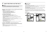
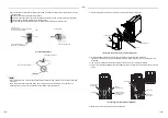
• To comply with the EMC (Electromagnetic Compatibility) standards, be sure to use the clamp filters that are
supplied accessories.
Clamp filter installation positions
• PMV Kit side:
A position 500 mm or less away from the shell of the PMV Kit body.
• Indoor unit side: A position between the PMV Kit body and the existing clamp filter and adjacent to the existing
clamp filter.
High wall without PMV (MMK-UP
1H
1) omits step 1) and 2).
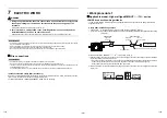
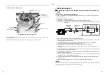
1) After the outdoor unit has been turned off, turn on power supply of the indoor unit only and open fully the pulse
motor valve (PMV) built in the indoor unit.
Turn on power supply of the indoor unit only under the condition that power supply of the outdoor unit is OFF.
* If power supply of the outdoor unit is turned on, the PMV of the indoor unit is not fully opened.
* Do not operate the remote controller until the PMV opens fully.
2) When 2 minutes or more passed after turning on power supply of the indoor unit, turn off power supply of the
indoor unit.
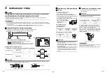
Connection cable
Indoor unit
Clamp filter
(Accessory)
Clamp filter
(Already installed)
PMV Kit side
Indoor unit side
Clamp filter
(Accessory)
* Install it adjacent to the existing clamp filter.
PMV Kit
500 mm or less
Indoor unit
ON
(OFF after 2- minute
or more)
Outdoor unit
Surely OFF
23-EN
24-EN

