background image


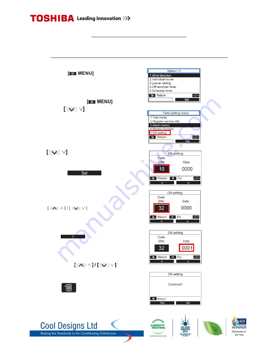
Common Configurable Control Options 

*Accessed via Toshiba hard wired remote controller

 RBC-AMS51E-ES


Relocation of room temperature sensing from return air to remote controller sensor 


1)


Press the “                       “  button to  
display the “

Menu screen

” 


2)


Press and hold the “                       “ button  
and the “                  “button at the same time  
for more than 4 seconds to display the  

            “

Field setting menu

”  


3)


Scroll down to item “

5

” using the         

            “                    “button. 
 
 
4)


Press “F2”                                 Code (DN) 10 
will be highlighted on the left of the display. 


5)


Scroll the Code (DN) to 32 using the  
“                                    “buttons. 


6)


When Code (DN) 32 is highlighted on the left 
press “                       [F2]” to highlight “

Data

”  

on the right. 
 

7)


Change “Data” from “0000” to “0001” by 
pressing the “                                       “   


8)


Press “                “follow on screen instructions. 


Summary of Contents for RBC-AMS51E

Page 1: ...Pocket Quick Reference Guide On the TOSHIBA RBC AMS51E Remote Controller ...

Page 2: ...nto the on board menu of the remote controller Controller Layout 1 ON OFF button 5 F1 button Illuminates when system is running Varies its functions according to the setting screen 2 Temperature up button 6 F2 button Used in the menu screen to select Varies its functions according to menu items the setting screen 3 Temperature down button 7 Cancel button Used in the menu screen to select Functions...

Page 3: ...n 2 Press and hold the button and the button at the same time for more than 4 seconds to display the Field setting menu 3 Scroll down to item 3 using the button 4 Press F2 A list of the latest 10 alarm codes along with date time and unit are displayed The oldest data are deleted in order to record the newest the date and time when the error occured for the first time are displayed for any repeated...

Page 4: ...Master outdoor unit over current detected shortly after start up H03 Current detected on Master outdoor unit whilst idle H06 Outdoor unit Low pressure detected by Ps sensor 0 2 bar 2 9 psig L03 Indoor unit Duplicated master indoor units in a group L07 Indoor unit in a group of units previously addressed as a single unit check addressing L08 Indoor units addresses not set check addressing L09 Indoo...

Page 5: ... the temperature measured by the TO ambient air sensor within the outdoor unit 4 Display s the remaining time until the filter sign is displayed 5 Display s the accumulated operating time of the system To access the second level of data display 5 Press the button to display the Menu screen 6 Press and hold the button and the button at the same time for more than 4 seconds to display the Field sett...

Page 6: ... If fitted o C 73 Fan Speed Upper rpm F1 Compressor Run Time x 100h VRF indoor data for Mini SMMS SMMS SMMSI SHRM equipment Code Indoor Data Code Indoor Data 00 Room Temp Control Temp o C 06 Indoor Discharge Temp If Used o C 01 Room Temp Remote Controller o C 08 PMV Position 0 10 02 TA Return Air Temp o C 0A Number of Connected Indoor Units No 03 TCJ Coil Liquid Temp o C 0b Indoor Capacity x 10 HP...

Page 7: ...mp o C 6 Compressor IPDU 3 Heat Sink Temp o C 7 TE2 Outdoor Coil Temp o C 7 Outdoor Fan IPDU Heat Sink Temp o C 8 TL Liquid Temp o C 8 Heating Cooling Recovery Controlled 9 TO Outdoor Ambient Temp o C 9 Pressure release A PMV 1 2 Opening A Discharge Temp Release B PMV 4 Opening B Follower Unit Release C Compressor 1 Current A F Outdoor Unit Size HP D Compressor 2 Current A Note Would be replaced w...

Page 8: ...s and hold the button and the button at the same time for more than 4 seconds to display the Field setting menu 3 Scroll down to item 5 using the button 4 Press F2 Code DN 10 will be highlighted on the left of the display 5 Scroll the Code DN to 32 using the buttons 6 When Code DN 32 is highlighted on the left press F2 to highlight Data on the right 7 Change Data from 0000 to 0001 by pressing the ...

Page 9: ... to display the Field setting menu 10 Scroll down to item 5 using the button 11 Press F2 Code DN 10 will be highlighted on the left of the display 12 Scroll the Code DN to 28 using the buttons 13 When Code DN 32 is highlighted on the left press F2 to highlight Data on the right 14 Change Data from 0000 to 0001 by pressing the 15 Press follow on screen instructions ...

Page 10: ... then press Set F2 button 4 Press the button to select the year month date time Press the F1 or F2 button to set the value 5 Press the button Setting ON and OFF Times scheduled operations 1 Press the button to display the Menu screen 2 Press the button to select option 5 Schedule timer then press the Set F2 button 3 Press the F1 button to turn On or F2 to turn off the schedule timer ...

Page 11: ...ect ON to set start time and set temperature settings Select OFF to set the stop time indicates that item has not been set 4 Press the F2 button to select time or temperature When is displayed time or temperature cannot be selected 5 Press the button to set time or temperature 6 Press the F1 to program the next pattern Up to 8 patterns per day can be programmed 7 Press the button Screen returns to...

Page 12: ...dule for the day selected is deleted 3 Press the F2 button to Return to the Condition setting screen To copy the settings of the previous day 1 Press the button on the day selection screen 2 Press the F1 button The schedule for the previous day is copied 3 Press the F2 button to Return to the Condition setting screen ...

Page 13: ...F2 button Energy Saving Ratio 1 Press the button to Select option 2 Energy Saving Ratio 2 Press the F1 or F2 to set the value The energy saving ratio can be set within the range from 50 to 100 by 1 increments The lower the value is set the higher the power saving effect Item Function 1 Energy Saving Operation Perform the power saving operation of the air conditioner 2 Set temp Range limit Set the ...

Page 14: ...rgy Saving Temperature Setting 1 Press the buttons to Select 2 Set temp range limit on the Energy Saving Screen and then press the F2 button 2 Press the button to set the temperature Press the F1 or F2 button to set the value 3 Press the button The screen returns to the Energy Saving Screen Setting appears and then the screen returns to the Energy saving operations screen ...

Page 15: ... individual operation for the ventilation unit is not actived 2 Fan Speed or 3 Mode 4 24H Ventilation off is available only for the air conditioning system using the Toshiba Air to Air Heat Exchanger VN M HE series appears on the detailed display during the ventilation operation when the ventilation unit other than the Toshiba Air to Air Heat Exchanger VN M HE series is used and the individual ope...

Page 16: ... 0844 800 0250 Toshiba Air Conditioning 24 7 technical support 0870 843 0333 Text back service 07624 803 017 Type fault code in lower case no spaces Cool Designs Ltd reserves the right to change the product specifications data and images without notice ...

Reviews: