background image

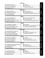
CONTENTS

SOMMAIRE

INHALT

INDICE

CONTENIDO

ÍNDICE

ÐÅÑÉÅ×ÏÌÅÍÁ

INHOUD

ITALIANO

ESPA

Ñ

OL

PORTUGU

Ê

S

ÅËËÇÍÉÊÁ

FRANCAIS

DEUTSCH

NEDERLANDS

ENGLISH

1

PRECAUTIONS FOR SAFETY .................................... 1

2

ACCESSORY AND REFRIGERANT ........................... 2

3

SELECTION OF INSTALLATION ................................ 3

4

REFRIGERANT PIPING .............................................. 7

5

EVACUATING ............................................................... 9

6

ELECTRICAL WORK ................................................. 11

7

FINAL INSTALLATION CHECKS .............................. 12

1

MESURES DE SECURITE ........................................ 14

2

ACCESSOIRES ET REFRIGERANT ......................... 15

3

CHOIX DE L’INSTALLATION ..................................... 16

4

TUYAUX DE REFRIGERANT .................................... 20

5

EVACUATION DE L’AIR ............................................. 22

6

INSTALLATION ELECTRIQUE .................................. 24

7

DERNIERES VERIFICATIONS DE L’INSTALLATION 25

1

SICHERHEITSVORKEHRUNGEN ............................ 27

2

ZUBEHÖR UND KÜHLMITTEL ................................. 28

3

VORBEREITUNGEN FÜR DIE INSTALLATION ........ 29

4

KÜHLMITTELLLEITUNGEN ..................................... 33

5

ENTLÜFTEN DER ROHRLEITUNGEN ..................... 35

6

ELEKTROINSTALLATION ......................................... 37

7

ÜBERPRÜFUNGEN NACH DER INSTALLATION .... 38

1

PRECAUZIONI PER LA SICUREZZA ....................... 40

2

ACCESSORI E REFRIGERANTE ............................. 41

3

SCELTA DEL POSTO D’INSTALLAZIONE ............... 42

4

TUBAZIONI DEL REFRIGERANTE .......................... 46

5

SVUOTAMENTO ........................................................ 48

6

ESECUZIONE DEI COLLEGAMENTI ELETTRICI .... 50

7

CONTRROLLI DI FINE INSTALLAZIONE ................. 51

1

PRECAUCIONES PARA SU SEGURIDAD ............... 53

2

ACCESORIOS Y  REFRIGERANTE ........................... 54

3

ELECCIONES PARA LA INSTALACIÓN .................. 55

4

CANALIZACIONES DE REGRIGERANTE ............... 59

5

EVACUACIÓN ............................................................ 61

6

TRABAJOS EN EL SISTEMA ELÉCTRICO ............. 63

7

COMPROBACIONES FINALES ................................ 64

1

PRECAUÇÕES DE SEGURANÇA ............................ 66

2

ACESSÓRIOS E REFRIGERANTE ........................... 67

3

SELECÇÃO DA INSTALAÇÃO ................................. 68

4

TUBAGEM DE REFRIGERANTE .............................. 72

5

EVACUAÇÃO ............................................................. 74

6

LIGAÇÕES ELÉCTRICAS ......................................... 76

7

VERIFICAÇÕES DE INSTALAÇÃO FINAIS ............. 77

1

VOORZORGSMAATREGELEN VOOR UW VEILIGHEID . 79

2

ACCESSOIRES EN KOELMIDDEL ........................... 80

3

VOORBEREIDINGEN ................................................ 81

4

KOELMIDDELLEIDINGEN ........................................ 85

5

ONTLUCHTEN ........................................................... 87

6

ELEKTRISCH GEDEELTE ........................................ 89

7

LAATSTE CONTROLES VAN DE INSTALLATIE ...... 90

ÐÑÏÖÕËÁÎÅÉÓ ÁÓÖÁËÅÉÁÓ ................................... 92


ÐÁÑÅËÊÏÌÅÍÏ ÊÁÉ ØÕÊÔÉÊÏ .............................. 93

!

ÅÐÉËÏÃÇ ÅÃÊÁÔÁÓÔÁÓÇÓ ...................................... 94

"

ÓÙËÇÍÙÓÅÉÓ ØÕÊÔÉÊÏÕ ........................................ 98

#

ÅÊÊÅÍÙÓÇ ............................................................. 100

$

ÇËÅÊÔÑÏËÏÃÉÊÁ .................................................. 102

%

ÔÅËÉÊÏÉ ÅËÅÃ×ÏÉ ÅÃÊÁÔÁÓÔÁÓÇÓ ..................... 103

Summary of Contents for RAV-SP1102AT-E

Page 1: ...ginnen In diesem Handbuch wird die Installation der Außeneinheit beschrieben Um die Raumeinheit zu installieren folgen Sie den Anweisungen in dem Handbuch das der Raumeinheit beiliegt Prima di installare il condizionatore d aria leggere con attenzione questo manuale d installazione Questo manuale descrive il metodo d installazione dell unità esterna Per l installazione dell unità interna fare rife...

Page 2: ...gerante convenzionale R22 per prevenire la distruzione dello strato di ozono dell atmosfera terrestre ADOPCIÓN DE NUEVO REFRIGERANTE Este aparato de aire acondicionado es un modelo reciente que incorpora el nuevo refrigerante HFC R410A en lugar del refrigerante convencional R22 para así evitar daños en la capa de ozono ADOPÇÃO DO NOVO REFRIGERANTE Este ar condicionado é um modelo novo que adopta u...

Page 3: ... 40 2 ACCESSORI E REFRIGERANTE 41 3 SCELTA DEL POSTO D INSTALLAZIONE 42 4 TUBAZIONI DEL REFRIGERANTE 46 5 SVUOTAMENTO 48 6 ESECUZIONE DEI COLLEGAMENTI ELETTRICI 50 7 CONTRROLLI DI FINE INSTALLAZIONE 51 1 PRECAUCIONES PARA SU SEGURIDAD 53 2 ACCESORIOSY REFRIGERANTE 54 3 ELECCIONES PARA LA INSTALACIÓN 55 4 CANALIZACIONES DE REGRIGERANTE 59 5 EVACUACIÓN 61 6 TRABAJOS EN EL SISTEMA ELÉCTRICO 63 7 COMP...

Page 4: ...istance force and impurity in it CAUTION To Disconnect the Appliance from Main Power Supply This appliance must be connected to the main power supply by means of a switch with a contact separation of at least 3 mm The installation fuse 25A D type must be used for the power supply line of this conditioner WARNING Ask an authorized dealer or qualified installation professional to install maintain th...

Page 5: ...ground wires for telephone cables Conform to the regulations of the local electric company when wiring the power supply Inappropriate grounding may cause electric shock Do not install the air conditioner in a location subject to a risk of exposure to a combustible gas If a combustible gas leaks and stays around the unit a fire may occur Required tools for installation work 1 Philips screw driver 2...

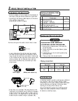
Page 6: ...abinet etc 500 Strong wind Strong wind 2 Supposing the wind direction during the operation season of the air conditioner install the unit so that the discharge port is set at right angle to the wind direction 4 Installation in the following places may result in some troubles Do not install the unit in such places below A place full of machine oil A place full of sulphuric gas A place where high fr...

Page 7: ...ree 1 Single unitIn installation 2 Serial installation of two or more units 1000 or more 300 or more 1500 or more 2000 or more 200 or more 300 or more 300 or more 1000 or more 200 or more 1000 or more 1000 or more 1000 or more 150 or more Obstacle also at the upper side Obstacles at both front and rear sides Open the upper side and both right and left sides The height of obstacle at both front and...

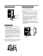
Page 8: ...lity increases when a knockout hole on the base plate is opened Open the knockout hole to outside using a screwdriver etc Refrigerant Piping Connection CAUTION TAKE NOTICE THESE IMPORTANT 4 POINTS BELOW FOR PIPING WORK 1 Keep dust and moisture away from inside the connecting pipes 2 Tightly connect the connection between pipes and the unit 3 Evacuate the air in the connecting pipes using VACUUM PU...

Page 9: ... be sure to mount the pipe cover The pipe cover is easily mounted by cutting off the slit at the lower part of the pipe cover How to remove the front panel 1 Remove screws of the front panel 2 Pull the front panel downward Removing the front panel the electric parts appear at the front side The metal pipes are attachable to the piping holes If the size of the used power pipe does not match with th...

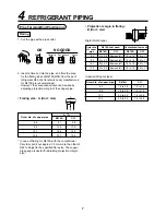
Page 10: ...than that of R22 to adjust to the specified flare size The copper pipe gauge is useful for adjusting projection margin size Imperial Wing nut type B Projection margin in flaring B Unit mm Rigid Clutch type A R410A R22 9 1 9 0 13 2 13 0 16 6 16 2 19 7 19 4 0 0 4 Outer dia of copper pipe 6 4 9 5 12 7 15 9 Outer dia of copper pipe 6 4 9 5 12 7 15 9 R410A tool used R410A R22 0 to 0 5 Same as left 0 to...

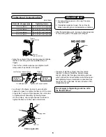
Page 11: ...sen or tighten the flare nut of the valve at liquid side Cover NO GOOD Valve at gas side Pressure of R410A is higher than that of R22 Approx 1 6 times Therefore using a torque wrench tighten the flare pipe connecting sections which connect the indoor outdoor units at the speci fied tightening torque Incomplete connections may cause not only a gas leak but also a trouble of the refrigeration cycle ...

Page 12: ...mp As shown in the figure connect the charge hose after the manifold valve are closed completely Tighten valve and caps of the charge port surely Disconnect the charge hose from the charge port Open fully the valve stem or the valve handle First at liquid side then gas side Leave the vacuum pump as it is for 1 or 2 minutes and check the indicator of the compound pressure gauge does not return Turn...

Page 13: ...1 Use the vacuum pump vacuum pump adapters and gauge manifold referring to the manuals attached to each tool before using them For the vacuum pump check oil is filled up to the specified line of the oil gauge 2 While the air is purged check again that the connecting port of charge hose which has a projection to push the valve core is firmly con nected to the charge port Valve handling precautions ...

Page 14: ...heir respective numbers on the terminal block of indoor and outdoor unit H07 RN F or 245 IEC 66 1 0 mm2 or more 2 When connecting the connecting cable to the outdoor unit terminal prevent water coming in the outdoor unit 3 Insulate the unsheathed cords conductors with electrical insulation tape Process them so that they do not touch any electrical or metal parts 4 For inter connecting cable do not...

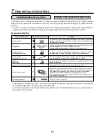
Page 15: ...ion by the remote controller Useful Functions Self Diagnosis by LED Indication In addition to the code checking by remote controller of the indoor unit troubles of the outdoor unit can be diag nosed by LED indications on the cycle control P C board of the outdoor unit Utilize them for various checks For the check by remote controller of the indoor unit refer to the Installation Manual of the indoo...

Page 16: ...s leakage detector Applicable to R22 model Changes As pressure is high it is impossible to measure by means of conventional gauge In order to prevent any other refrigerant from being charged each port diameter is changed In order to increase pressure resisting strength hose materials and port size are changed to 1 2 UNF 20 threads per inch When purchasing a charge hose be sure to check the port si...

Page 17: ...den Questo prodotto è conforme alla direttiva 2002 95 CE e per disfarsene non deve essere gettato con la spazzatura della casa Este producto cumple con la Directiva 2002 95 EC y no se puede desechar como la basura municipal Este produto respeita a Directiva 2002 95 EC e não pode ser deitado fora como lixo municipal Dit product is in overeenstemming met richtlijn 2002 95 EC en mag niet als huishoud...

Reviews: