background image

– 23 –

45-EN

46-EN

Periodic Maintenance

• For environmental conservation, it is strongly recommended that the indoor and outdoor units of the air 

conditioner in use be cleaned and maintained regularly to ensure efficient operation of the air conditioner.
When the air conditioner is operated for a long time, periodic maintenance (once a year) is recommended. 
Furthermore, regularly check the outdoor unit for rust and scratches, and remove them or apply rustproof 
treatment, if necessary.
As a general rule, when an indoor unit is operated for 8 hours or more daily, clean the indoor unit and outdoor 
unit at least once every 3 months. Ask a professional for this cleaning / maintenance work.
Such maintenance can extend the life of the product though it involves the owner’s expense.
Failure to clean the indoor and outdoor units regularly will result in poor performance, freezing, water leakage, 
and even compressor failure.

Inspection before maintenance

Following inspection must be carried out by a qualified installer or qualified service person.

* Refer to the Service Manual for how to remove.

Maintenance List

Parts

Inspection method

Heat exchanger*

Open the air intake grille to remove the bell mouth and the fan, and then check the heat exchanger 

if there is any clogging or damages.

Fan motor

Check if any abnormal noise can be heard.

Fan

Open the air intake grille and check the fan if there are any waggles, damages or adhesive dust.

Filter

Open the air intake grille and check if there are any stains or breaks on the filter.

Drain pan*

Remove the panel, the bell mouth and the drain pan, and then check if there is any clogging, 

abnormal smell or drain water pollution.

Part

Unit

Check (visual / auditory)

Maintenance

Heat exchanger

Indoor / outdoor

Dust / dirt clogging, scratches

Wash the heat exchanger when it is 

clogged.

Fan motor

Indoor / outdoor

Sound

Take appropriate measures when 

abnormal sound is generated.

Filter

Indoor

Dust / dirt, breakage

• Wash the filter with water when it is 

contaminated.

• Replace it when it is damaged.

Fan

Indoor

• Vibration, balance
• Dust / dirt, appearance

• Replace the fan when vibration or 

balance is terrible.

• Brush or wash the fan when it is 

contaminated.

Air intake / discharge 

grilles

Indoor / outdoor

Dust / dirt, scratches

Fix or replace them when they are 

deformed or damaged.

Drain pan

Indoor

Dust / dirt clogging, drain 

contamination

Clean the drain pan and check the 

downward slope for smooth drainage.

Ceiling panel, louvers

Indoor

Dust / dirt, scratches

Wash them when they are contaminated 

or apply repair coating.

Exterior

Outdoor

• Rust, peeling of insulator
• Peeling / lift of coat

Apply repair coating.

11

Troubleshooting

Confirmation and check

Troubleshooting history and confirmation

You can check the troubleshooting history with the following procedure if a problem occurs with the air conditioner. 
(The troubleshooting history records up to 4 incidents.)
You can check it during operation or when operation is stopped.
• If you check the troubleshooting history during OFF timer operation, the OFF timer will be cancelled. 

If a problem occurs with the air 
conditioner, the OFF timer indicator 
alternately shows the check code and 
the indoor Unit No. in which the 
problem occurred.

Procedure

Description of operation

1

Push the OFF timer button for over 10 seconds 

and the indicators appear as an image indicating 

the troubleshooting history mode has been 

entered. If [

Service check] is displayed, the 

mode enters in the troubleshooting history mode.

• [01: Order of troubleshooting history] appears in the 

temperature indicator.

• The OFF timer indicator alternately shows the [check 

code] and the [indoor Unit No.] in which the problem 
occurred. 

2

Each time the setting button is pushed, the recorded 

troubleshooting history is displayed in sequence.
The troubleshooting history appears in order from [01] 

(newest) to [04] (oldest).

CAUTION

CAUTION

• In the troubleshooting history mode, DO NOT 

push the Menu button for over 10 seconds, doing 
so deletes the entire troubleshooting history of 
the indoor unit.

3

After you have finished checking, push the ON/OFF
button to return to the regular mode.
• If the air conditioner is operating, it remains operated 

even after the ON/OFF button has been pushed.
To stop its operation, push the ON/OFF button again.

Check code

The indoor Unit No. in which

the problem occurred.

3

1

2

Summary of Contents for RAV-HM301MUT-E

Page 1: ...AIR CONDITIONER SPLIT TYPE Installation Manual R32 Indoor Unit Compact 4 Way type RAV HM301MUT E RAV HM401MUT E RAV HM561MUT E Model name For commercial use English ...

Page 2: ...erant HFC R32 which does not destroy the ozone layer This indoor unit is for the R32 refrigerant Be sure to combine with an outdoor unit for the R32 refrigerant Product information of ecodesign requirements Regulation EU 2016 2281 http ecodesign toshiba airconditioning eu en Contents 1 Precautions for safety 3 2 Accessory parts 7 3 Selection of installation place 7 4 Installation 9 5 Drain piping ...

Page 3: ... pertaining to this electrical work as stipulated by the local laws and regulations and he or she is a person who has been trained in matters relating to electrical work on the air conditioners made by Toshiba Carrier Corporation or alternatively he or she has been instructed in such matters by an individual or individuals who have been trained and is thus thoroughly acquainted with the knowledge ...

Page 4: ...t in water leakage electric shock or fire Do not use any refrigerant different from the one specified for complement or replacement Otherwise abnormally high pressure may be generated in the refrigeration cycle which may result in a failure or explosion of the product or an injury to your body Before opening the intake grille of the indoor unit or service panel of the outdoor unit set the circuit ...

Page 5: ...r conditioner is running Do not place any combustion appliance in a place where it is directly exposed to the wind of air conditioner otherwise it may cause imperfect combustion Appliance and pipe work shall be installed operated and stored in a room with a floor area larger than Amin m How to get Amin m Amin M 2 5 0 22759 h0 M is the refrigerant charge amount in appliance in kg h0 is the installa...

Page 6: ...on using a solderless terminal etc Connection trouble in the places where the wire is connected in the middle may give rise to smoking and or a fire Electrical wiring work shall be conducted according to law and regulation in the community and Installation Manual Failure to do so may result in electrocution or short circuit Test run Before operating the air conditioner after having completed the w...

Page 7: ...ossibly resulting in rupture injury or other trouble 1 Refer to the Definition of qualified installer or qualified service person This Air Conditioner has adopted a refrigerant HFC R32 which does not destroy the ozone layer As the R32 refrigerant is easily affected by impurities such as moisture oxidized film oil etc due to the high pressure be careful not to allow the moisture dirt existing refri...

Page 8: ...lace where drained water will not cause any problem Avoid installing in the following places Place exposed to air with high salt content seaside area or place exposed to large quantities of sulfide gas hot spring The unit should be used in these places special protective measures are needed A restaurant kitchen where a lot of oil is used or place near machines in a factory Oil adhering to the heat...

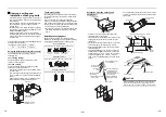
Page 9: ... 10 mm or more 200 200 15 or more 271 or more 1000 or more 271 or more 1000 or more 1000 or more An obstacle 15 or more 1 400 or more 560 or more 3 Check port 450 2 Check port 450 1000 or more Ceiling height Unit m When the height of the ceiling exceeds the distance of the item Standard 4 way in below table the warm air is difficult to reach the floor It is necessary to change the setup value of t...

Page 10: ... to 594 13 to 20 Panel external dimension 620 13 to 20 13 to 20 Ceiling open dimension 580 to 594 Panel external dimension 620 External view Unit mm 23 5 0 146 191 320 214 256 93 40 132 173 257 70 53 193 154 146 8 3 12 184 ØA Ceiling open dimension 580 to 594 Bottom face of ceiling Wiring entry for remote control Unit external dimension 575 Refrigerant pipe connecting port Gas side Refrigerant pip...

Page 11: ...ccording to size in the unit external view as shown below Hanging bolt M10 or W3 8 4 pieces Nut M10 or W3 8 12 pieces Indoor unit Panel fixing screw Installation pattern Accessory Installation pattern attachment hole New concrete slab Install the bolts with insert brackets or anchor bolts Steel flame structure Use existing angles or install new support angles Existing concrete slab Use a hole in a...

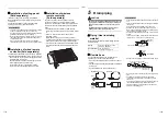
Page 12: ...ireless type remote controller can be installed in the same room 7 m o r le s s 5 Drain piping CAUTION CAUTION Following the Installation Manual perform the drain piping work so that water is properly drained and apply a heat insulation so as not to cause a dew drop Inappropriate piping work may result in water leakage in the room and wet of furniture Piping Heat insulating material Require the fo...

Page 13: ...6 mm or less Underside of ceiling Indoor unit 300 mm or less Rising up 850 mm or less After the electric work has finished pour water during COOL mode operation If the electric work has not yet finished pull out the float switch connector CN34 Red from the electrical control box and check draining by plugging the single phase 220 240 V power to the terminal blocks and If doing so the drain pump mo...

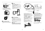
Page 14: ...mm Liquid side 6 4 mm 6 4 mm Outside diameter size R32 or R410A tool used Conventional tool used 6 4 9 5 0 0 5 1 0 1 5 12 7 Outside diameter size A 0 0 4 6 4 9 1 9 5 13 2 12 7 16 6 B A Tightening connection CAUTION CAUTION Do not apply excessive torque Otherwise the nut may crack depending on the conditions Tightening torque of flare pipe connections Incorrect connections may cause not only a gas ...

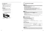
Page 15: ...re is connected in the middle may give rise to smoking and or a fire CAUTION CAUTION For power supply specifications follow the Installation Manual of outdoor unit Do not connect 220 240 V power to the terminal blocks for control wiring Otherwise the system will fail Do not damage or scratch the conductive core and inner insulator of power and system interconnection wires during peeling them Perfo...

Page 16: ... units refer to the following table Remote controller wiring Wiring between indoor unit and outdoor unit 1 Figure below shows the wiring connections between the indoor and outdoor units and between the indoor units and remote controller The wires indicated by the broken lines or dot and dash lines are provided at the locally 2 Refer to the both indoor and outdoor unit wiring diagrams 3 The power o...

Page 17: ...cable type and diameter Cord clamp can be attached on either right or left side When twin system are connected clamp two cables with one cord clamp Wire type Specification Cord clamping position Cabtyre cable 3 core stranded wire 2 5 mm Side D Cabtyre cable 4 core stranded wire 1 5 mm Side C Side D Space 8 5 mm Side C Space 4 mm Hook part Screws Cover of electrical control box CAUTION CAUTION 1 Ma...

Page 18: ...p control change cyclically Select the indoor unit to change settings for The fan of the selected indoor unit runs and the louvers start swinging The indoor unit can be confirmed for which to change settings 3 Push OFF timer button to confirm the selected indoor unit 4 Push the menu button to make Code No flash Change Code No with setting button 5 Push the menu button to make Set data flash Change...

Page 19: ...cur during cooling mode When the setting has been determined lights up Set data Detection temperature shift value 0000 No shift 0001 1 C 0002 2 C Factory default 0003 3 C 0004 4 C 0005 5 C 0006 6 C Set data Filter sign term 0000 None 0001 150 H 0002 2500 H Factory default 0003 5000 H 0004 10000 H Set data Swing of louvers 0001 Standard swing Factory default 0002 Dual swing 0003 Cycle swing 1 0001 ...

Page 20: ...r Indoor unit Indoor unit Indoor unit Indoor unit Group control for system of multiple units One group can control up to 16 TU2C Link or 8 TCC Link indoor units with one remote controller Refer to the Wiring specifications Group control in single system For wiring procedure and wiring method of the individual line Identical refrigerant line system follow to Electrical connection Wiring between lin...

Page 21: ...push the buttons 3 Push the ON OFF button return to the normal mode 9 Test run Before test run Before turning on the power supply carry out the following procedure 1 By using 500 V megger check that resistance of 1 MΩ or more exists between the terminal block 1 to 3 and the earth grounding work If resistance of less than 1 MΩ is detected do not run the unit 2 Check the valve of the outdoor unit be...

Page 22: ...perature to 17 C with the temp setup buttons After confirming a signal receiving sound beep immediately set the temperature to 30 C with the temp setup buttons Monitoring function This function can be used to call the service monitor mode from the remote controller during a test run to obtain the temperature of the sensors of the remote controller indoor unit and outdoor unit 1 Push and hold menu ...

Page 23: ...ay from the grille and remove Hook Fall preventive strap 4 Cleaning with water or vacuum cleaner If dirt is heavy clean the air filter using tepid water with a neutral detergent or just water After cleaning with water dry the air filter sufficiently in a shaded place 5 Mount the air filter 6 Close the air intake grille Check that the fall preventive strap of the air intake grille is attached to th...

Page 24: ...st dirt appearance Replace the fan when vibration or balance is terrible Brush or wash the fan when it is contaminated Air intake discharge grilles Indoor outdoor Dust dirt scratches Fix or replace them when they are deformed or damaged Drain pan Indoor Dust dirt clogging drain contamination Clean the drain pan and check the downward slope for smooth drainage Ceiling panel louvers Indoor Dust dirt...

Page 25: ...nsor TA indoor P C board Open circuit or short circuit of the room temp sensor TA was detected Auto reset F12 ALT TS sensor trouble Outdoor TS sensor may be displaced disconnected or short circuited Entire stop F13 ALT Heat sink sensor trouble Outdoor Abnormal temperature was detected by the temp sensor of the IGBT heat sink Entire stop F15 ALT Temp sensor connection trouble Outdoor Temp sensor TE...

Page 26: ... may be gas leakage from the pipe or connecting part Check for gas leakage Entire stop P19 ALT 4 way valve trouble Outdoor Indoor 4 way valve indoor temp sensors TC TCJ An trouble was detected due to temperature drop of the indoor unit heat exchanger sensor when heating Auto reset P20 ALT High pressure protective operation Outdoor High pressure protection Entire stop P22 ALT Outdoor unit fan troub...

Page 27: ...EB99847701 DH91308201 ...
Reviews: