background image

FILE NO. SVM-03008

– 26 –

8-2. Description of Operation Circuit

Turning [ON] the breaker flashes the operation
lamp. (1Hz)
This is the display of power-ON (or notification of
power failure).

When pushing [START/STOP] button of the
remote control, receive sound is issued from the
main unit, and the next operations are performed
together with opening the vertical air flow louvers.

8-2-1. Cooling operation

(The Remote Control MODE Button is Set to
the COOL   Position)

Once the setting is made, the operation mode is
memorized in the microcomputer so that the same
operation can be effected thereafter simply by
pushing [START/STOP] button.

A cooling operation signal is transmitted to
outdoor unit.

The outdoor unit controls the outdoor fan relay
R01, R02 and R03, and the compressor motor
speed according to the operation command signal
sent from the indoor unit.

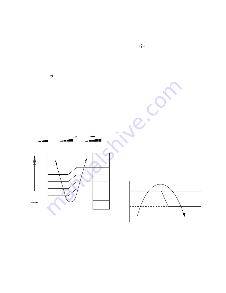
When [FAN] button is set to AUTO, the indoor fan
motor operates as shown in Fig. 8-2-1. When
[FAN] button is set to LOW  , LOW

,

MED 

, MED

, HIGH 

, the

motor operates with a constant air flow.

NOTE :
*1: Calculated from difference in motor speed of M+

and L, and controlled.

Fig. 8-2-1 Setting of air flow [Fan AUTO]

(1) Cooling capacity control

The cooling capacity and room temperature
are controller by changing the compressor
motor speed according to both the difference
between the temperature detected by the room
temperature sensor and the temperature set by
TEMP 

 button and also any change in room

temperature.

When compressor has been activated or
reactivated, it operates with Max.41 rps for 2
minutes, with Max.91 rps from 2 minutes to 3
minutes, and with Max.88 rps after 3 minutes
passed.

When room temperature is lower than set
temperature, indoor fan motor is operated at
fan speed L as shown in Fig. 8-2-1 while the
outdoor unit stops.

(2) Prevent-freezing control

If temperature of indoor heat exchanger detected
by the indoor heat exchanger sensor is 5

°

C lower,

compressor motor speed is gradually lowered to
prevent freezing of the indoor heat exchanger. If
temperature is 7

°

C or higher, return the operation

to the above item (1).

(3) Current release control

The input current of compressor and outdoor fan
motor (Precisely inverter main circuit control
section) which occupy most of air conditioner input
is detected by the outdoor current sensor, and
compressor motor speed is gradually lowered so
that current value does not exceed 9.0A if current
value exceeds 9.0A. When the current value
lowers to 8.5A, return the operation to the above
item (1).

Fig. 8-2-2

Set 
temp.

+3

M+

*1

*1

*1

L

+2.5

+2

+1.5

+1

+0.5

0

0.5

°

C

(Room temp.) 

 (Set temp.)

In normal
operation

Normal control

9.0

8.5

Current v

a

lue (A)

Comp. motor 
speed down

Comp. motor 
speed keep

Summary of Contents for RAS-13UAV-E2

Page 1: ...FILE NO SVM 03008 SERVICE MANUAL AIR CONDITIONER SPLIT WALL TYPE Jun 2003 RAS 13UKV E2 RAS 13UAV E2 ...

Page 2: ...Unit 4 2 Outdoor Unit 5 SPECIFICATION OF ELECTRICAL PARTS 5 1 Indoor Unit 5 2 Outdoor Unit 6 REFRIGERANT CYCLE DIAGRAM 6 1 Refrigerant Cycle Diagram 6 2 Operation Data 7 CONTROL BLOCK DIAGRAM 7 1 Indoor Unit 7 2 Outdoor Unit Inverter Assembly 8 OPERATION DESCRIPTION 8 1 Outlined of Air Conditioner Control 8 2 Description of Operation Circuit 8 3 Temporary Operation 8 4 Auto Restart Function 8 5 Fi...

Page 3: ...ptom 10 6 Check Code 1C Miswiring in indoor outdoor units and 1E 10 7 How to Diagnose Trouble in Outdoor Unit 10 8 How to Check Simply the Main Parts 10 9 How to Simply Judge Whether Outdoor Fan Motor is Good or Bad 11 HOW TO REPLACE THE MAIN PARTS 11 1 Indoor Unit 11 2 Microcomputer 11 3 Outdoor Unit 12 EXPLODED VIEWS AND PARTS LIST 12 1 Indoor Unit E Parts Assy 12 2 Indoor Unit 12 3 Outdoor Unit...

Page 4: ... Outdoor unit Unit model RAS 13UAV E2 Dimension Height mm 550 Width mm 780 Depth mm 720 Net weight kg 40 Compressor Motor output W 750 Type Twin rotary type with DC inverter variable speed control Model DA91A1F 45F Fan motor output W 43 Air flow rate Cooling Heating m3 h 2410 2410 Piping connection Type Flare connection Indoor unit Liquid side 6 35 Gas side 9 52 Outdoor unit Liquid side 6 35 Gas s...

Page 5: ...oor DB 7 C WB 6 C Air flow High Pipe length 5m 230V 1 3 Capacity Variation Ratio According to Temperature Cooling Heating 120 110 100 90 80 70 60 50 40 30 20 10 0 10 9 8 7 6 5 4 3 2 1 0 1 2 3 4 5 6 7 8 9 10 Capacity ratio Outdoor temp C Conditions Indoor DB 20 C Indoor air flow High Pipe length 5m Capacity ratio 100 3 5 kW 105 100 95 90 85 80 75 70 65 60 55 50 32 34 36 38 40 42 33 35 37 39 41 43 O...

Page 6: ...n in Table 2 2 1 Never use copper pipes thinner than 0 8 mm even when it is available on the market 2 REFRIGERANT R410A This air conditioner adopts the new refrigerant HFC R410A which does not damage the ozone layer The working pressure of the new refrigerant R410A is 1 6 times higher than conventional refrigerant R22 The refrigerating oil is also changed in accordance with change of refrigerant s...

Page 7: ...hat a clamp bar and copper pipe have been cleaned By means of the clamp bar perform the flare processing correctly Use either a flare tool for R410A or conventional flare tool Flare processing dimensions differ according to the type of flare tool When using a conventional flare tool be sure to secure dimension A by using a gauge for size adjustment Fig 2 2 1 Flare processing dimensions 2 2 2 Proce...

Page 8: ...0 to 2 0 5 8 15 88 1 0 0 to 0 5 0 5 to 1 0 1 0 to 2 0 Table 2 2 4 Dimensions related to flare processing for R22 Nominal diameter Outer diameter mm Thickness mm Flare tool for R410A clutch type Dimension mm A B C D 1 4 6 35 0 8 9 1 9 2 6 5 13 17 3 8 9 52 0 8 13 2 13 5 9 7 20 22 1 2 12 70 0 8 16 6 16 0 12 9 23 26 5 8 15 88 1 0 19 7 19 0 16 0 25 29 Table 2 2 5 Flare and flare nut dimensions for R410...

Page 9: ... nut may crack and may be made non removable When choosing the tightening torque comply with values designated by manufacturers Table 2 2 7 shows reference values Note When applying oil to the flare surface be sure to use oil designated by the manufacturer If any other oil is used the lubricating oils may deteriorate and cause the compressor to burn out Tightening torque of torque Nominal Outer di...

Page 10: ... used with for R410A equipment can conventional refrigerant be used 1 Flare tool Pipe flaring Yes Note 1 2 Copper pipe gauge Flaring by for adjusting projection conventional flare Yes Note 1 Note 1 margin tool 3 Torque wrench Connection of Yes For 12 70 flare nut 4 Gauge manifold 5 Charge hose 6 Vacuum pump adapter Vacuum evacuating Yes 7 Electronic balance for Refrigerant charge Yes refrigerant c...

Page 11: ...ter does not return Set the refrigerant cylinder to the electronic balance connect the connecting hose to the cylinder and the connecting port of the electronic balance and charge liquid refrigerant For refrigerant charging see the figure below 1 Never charge refrigerant exceeding the specified amount 2 If the specified amount of refrigerant cannot be charged charge refrigerant bit by bit in COOL ...

Page 12: ... solderability 2 Phosphor bronze brazing filler Phosphor bronze brazing filler is generally used to join copper or copper alloy 3 Low temperature brazing filler Low temperature brazing filler is generally called solder and is an alloy of tin and lead Since it is weak in adhesive strength do not use it for refrigerant pipes 1 Phosphor bronze brazing filler tends to react with sulfur and produce a f...

Page 13: ...ical knowledge it must be performed by a person qualified In order to prevent the oxide film from occurring in the pipe interior during brazing it is effective to proceed with brazing while letting dry Nitrogen gas N2 flow Never use gas other than Nitrogen gas 1 Brazing method to prevent oxidation 1 Attach a reducing valve and a flow meter to the Nitrogen gas cylinder 2 Use a copper pipe to direct...

Page 14: ...08 48 48 26 45 190 40 32 64 590 320 620 235 235 215 215 90 90 275 45 150 150 160 160 120 80 53 6 60 Hanger Hanger Hanger Hanger Hanger Drain hose 0 54m Connecting pipe 0 43m Flare 6 35 For stud bolt 8 10 For stud bolt 6 Installation plate outline Center line Minimum distance to ceiling 170 or more Minimum distance to ceiling 170 or more 65 or more Minimum distance to ceiling Wireless remote contro...

Page 15: ...re A Detail drawing Back Leg 600 32 5 115 125 310 302 530 265 120 75 5 4 310 302 6 Hole 436 270 600 780 90 310 330 62 30 Drain outlet FAN GUARD Z View 600 320 Installation dimension 600 or more 600 or more Air outlet Air inlet 100 or more 4 x 11 x 14 Long holes For 8 10 anchorbolt Z COVER PV 6 Hole R15 36 52 310 102 302 11 x 14 Hole 2 11 x 14 Hole For 8 10 anchor bolt A ...

Page 16: ...heck the primary and secondary voltage of the transformer Check the fluctuating voltage between 2 and 3 DC15 to 60 V Check to see if the fuse blows out Check the R04 of the varistor Check the voltage at the No 4 pin on CN13 connector of the infrared receiver Check the transformer and the power supply circuit of the rated voltage Check the voltage at the white lead of the louver motor Check the tra...

Page 17: ...V FM PULSE MODULATING VALVE SURGE ABSORBER COIL for 4 WAY VALVE RELAY 1 1 2 2 1 1 2 2 TD 3 3 1 1 2 2 3 3 TO 1 1 2 2 TS 1 1 2 2 3 3 1 1 2 2 3 3 4 4 5 5 6 6 1 1 2 3 4 5 1 2 3 4 5 YEL PNK GRY 1 2 3 1 2 3 RED PUR P14 CN300 CN301 Q300 P13 P12 P11 P02 P03 P01 VARISTOR F04 FUSE T3 15A F01 FUSE T25A WHI BLK POWER SUPPLY 220 240V 50 60Hz TO INDOOR UNIT THERMOSTAT FOR COMPRESSOR CONVERTER MODULE IGBT MODULE...

Page 18: ...0µH Noise filter L03 ADR2520 R15TB 15A 0 6mH Primary side DC280V Secondary 2 DC DC transformer SWT 43 side 7 5 V x 1 13 V x 1 26 5V x 3 16 V x 1 15 V x 1 3 Reactor CH 57 Z T L 10mH 16A x 2 4 Outside fan motor ICF 140 43 1 DC140 V 43 W 5 Suction temp sensor Inverter attached 10 kΩ 25 C TS sensor 6 Discharge temp sensor Inverter attached 62 kΩ 20 C TD sensor 7 Outside air temp sensor Inverter attach...

Page 19: ...UNIT T1 TO Temp measurement Indoor heat exchanger Cross flow fan Deoxidized copper pipe Outer dia 6 35 mm Thickness 0 8 mm Sectional shape of heat insulator Allowable height difference 10m Allowable pipe length Max 15 m P Pressure measurement Gauge attaching port Vacuum pump connecting port Strainer Pulse modulating valve at liquid side SEV16RC3 1 5 x 200s 1 5 x 200s TD 4 way valve CHV 0213 Compre...

Page 20: ...V E2 0 8 to 1 0 9 to 11 49 to 45 High High 77 Model name Standard pressure P MPa Heat exchanger pipe temp T1 C T2 C Indoor fan mode Outdoor fan mode Compressor revolution rps Temperature condition C Indoor Outdoor 20 7 6 13UKV E2 2 5 to 2 7 42 to 44 0 to 3 High High 83 Model name Standard pressure P MPa Heat exchanger pipe temp T1 C T2 C Indoor fan mode Outdoor fan mode Compressor revolution rps 6...

Page 21: ...pressor Motor Revolution Control Timer Serial Signal Communication Processing Temperature Processing Functions M C U Indoor Unit Control Panel From Outdoor Unit Remote Control Heat Exchanger Sensor Temperature Sensor Infrared Rays Signal Receiver Infrared Rays Initiallizing Circuit Clock Frequency Oscillator Circuit Louver Motor 36 7KHz Power Supply Circuit Noise Filter Filter Sign Display PRE DEF...

Page 22: ... Rotor position detect circuit Rotor position detect circuit PWM synthesis function Input current release control IGBT over current detect control Outdoor fan control High power factor correction control Inverter output frequency control A D converter function P M V control Discharge temp control 4 way valve control Signal communication to indoor unit P M V Pulse Modulating Valve M C U Micro Contr...

Page 23: ...ng operation Temp measurement by outdoor heat exchanger and control for 4 way valve and outdoor fan 8 OPERATION DESCRIPTION 8 1 Outlined of Air Conditioner Control This air conditioner is a capacity variable type air conditioner which uses DC motor for the indoor fan motor and the outdoor fan motor And the capacity proportional control compressor which can change the motor speed in the range from ...

Page 24: ...ges compressor motor speed by changing AC 220 240 V power to DC once and controls capac ity by changing supply power status to the compressor with transistor module includes 6 transistors The outline of the control is as follows The revolution position and revolution speed of the motor are detected by detecting winding electromotive force of the compressor motor under operation and the revolution ...

Page 25: ... control 1 Vertical air flow louvers Positions of vertical air flow louvers are automatically controlled according to the operation status AUTO A COOL DRY HEAT and FAN ONLY Besides positions of vertical air flow louvers can be arbitrarily set by pushing the FIX button 2 Swing If the SWING button is pressed during running operation vertical air flow louvers start swinging When the FIX button is pus...

Page 26: ...an lock occurred due to entering of foreign matter the air conditioner stops and an alarm is displayed COOL DRY Table 8 1 3 HEAT Table 8 1 4 Model name RAS 13UAV E2 Compressor revolution rps To 16 8 To 57 4 From 58 0 Outdoor temp sensor TO TO 5 C 390 650 840 TO 5 C 650 650 840 ECONO operation TO 5 C 390 390 650 TO 5 C 390 650 650 TO is abnormal 390 650 840 Model name RAS 13UAV E2 Compressor revolu...

Page 27: ...nging the compressor motor speed according to both the difference between the temperature detected by the room temperature sensor and the temperature set by TEMP button and also any change in room temperature When compressor has been activated or reactivated it operates with Max 41 rps for 2 minutes with Max 91 rps from 2 minutes to 3 minutes and with Max 88 rps after 3 minutes passed When room te...

Page 28: ...ne Slow up zone of motor speed When TD detect value is 98 C or higher operating motor speed is slowly up 3 Control 3 C zone Keep zone When TD detect value is 105 C or higher operating motor speed is not changed if raising operation speed 4 Control 4 D zone Slow down zone of motor speed When TD detect value is 108 C or higher operating motor speed is slowly down 5 Control 5 E zone Normal down of mo...

Page 29: ...peed is performed The indoor fan motor operates as shown in Fig 8 2 5 Fan speed is AUTO only The outdoor fan motor operates as described in Table 8 1 3 and the compressor motor speed according to the operation command signal sent from the indoor unit NOTE 1 Middle motor speed between L and SUL Fig 8 2 5 Setting of air flow 8 2 3 Heating operation Transferring of heat operation signal from indoor u...

Page 30: ...f the compressor motor The power coupler IC20 for 4 way valve is turned on and turned off in defrost operation 1 Heating capacity control Calculate the difference between temperature detected by room temp sensor every minute and the set temp set on Temp indicator and variation amount of room temp Then obtain the correction amount of the com mand signal and correct the current frequency command sig...

Page 31: ...in Fig 8 2 9 the operation mode COOL DRY HEAT is selected according to the outside temperature and room temperature when the operation has started The operation in Fan mode continues until an operation mode is selected If the room temperature is 20 C or higher when AUTO operation started within 2 hours after HEAT operation had stopped select an operation mode after Fan operation of ultra low fan I...

Page 32: ...by the remote controller is accepted Using the Auto Restart function the Temporary Auto operation starts when power failure is reset 8 3 2 Temporary cooling operation When the TEMPORARY operation button keeps pushed for 10 seconds Cooling operation of which compressor motor speed and the indoor fan speed are fixed starts Compressor motor speed 13 30 rps Indoor fan speed Low When the TEMPORARY oper...

Page 33: ...e this function is being set if the unit is in operation the orange lamp is on This function can not be set if the timer operation has been selected When the unit is turned on by this function the louver will not swing even though it was swinging automatically before shutting down Operation Motions Push TEMPORARY button for more The unit is on standby than three seconds The unit starts to operate ...

Page 34: ...ons Push TEMPORARY button for more The unit is on standby than three seconds The unit starts to operate The orange lamp is on After approx three seconds The unit beeps three times The lamp changes from and continues to operate orange to orange If the unit is not required to operate at this time push TEMPORARY button once more or use the remote control to turn it off TEMPORARY button 0 3S Operation...

Page 35: ...eiving beep is heard 8 8 8 8 8 Off timer button OFF Push this button to set the OFF timer 9 9 9 9 9 On timer button ON Push this button to set the ON timer Reserve button SET Push this button to reserve time settings A receiving beep is heard Cancel button CLR Push this button to cancel ON timer and OFF timer A receiving beep is heard High power button Hi POWER Push this button to start the high p...

Page 36: ...r positioning and operation Five selectable positions Automatic Swing 5 5 5 5 5 FAN speed display Indicates the selected fan speed AUTO or one of five fan speed levels LOW LOW MED MED HIGH can be indicated Indicates AUTO when the operating mode is either AUTO or Dry 6 6 6 6 6 TIMER and clock time display The time set for timer operation or clock time is indicated The present time is always indicat...

Page 37: ...ange If the difference between the preset tempera ture and the room temperature is big the horizontal louver moves to the Hi POWER position automatically Then when the differ ence between them gets smaller the horizontal louver returns automatically 3 Heating operation The preset temperature increases 2 C The value of the preset temperature on the remote control does not change If the difference b...

Page 38: ...entional refrigerant and different size tools are also required Accordingly special tools are required for the new refrigerant R410A as shown below For connecting pipes use new and clean piping materials with high pressure withstand capabilities designed for R410A only and ensure that water or dust does not enter Moreover do not use any existing piping as its pressure withstand may be insufficient...

Page 39: ... INSTALLATION WORK IMMEDIATELY LET FRESH AIR INTO THE ROOM IF THE REFRIGERANT GAS IS HEATED BY FIRE OR SOMETHING ELSE IT CAUSES GENERATION OF POISONOUS GAS WARNING Never modify this unit by removing any of the safety guards or bypassing any of the safety interlock switches Do not install in a place which cannot bear the weight of the unit Personal injury and property damage can result if the unit ...

Page 40: ...ore 600 mm or more 100 mm or more from wall Saddle Do not allow the drain hose to get slack Make sure to run the drain hose sloped downward Cut the piping hole sloped slightly Left Rear left Right Rear right Bottom right Bottom left The auxiliary piping can be connected the left rear left rear right right bottom right or bottom left 250 mm or more from wall 6 Purifying filter 5 Zeolite filter Befo...

Page 41: ...strong wind Use 8 mm or 10 mm anchor bolts and nuts If it is necessary to drain the defrost water attach drain nipple to the bottom plate of the outdoor unit before installing it Parts name Refrigerant piping Liquid side 6 35 mm Gas side 9 52 mm Pipe insulating material polyethylene foam 6 mm thick Putty PVC tapes Part Code A B C Q ty One each 1 One each Diffuser Suction side Drain hole 600 115 31...

Page 42: ... No 7 8 9 Others Name Owner s manual Installation manual Part name Q ty Mounting screw 4 x 25 s x 6 Flat head wood screw 3 1 x 16 s x 2 Drain nipple x 1 This model is not equipped with an extension drain hose Option For the extension drain hose use an optionally available RB 821SW or commercially available one 9 1 3 Accessory and installation parts The part marked with asterisk is packaged with th...

Page 43: ...t diameter has been changed In order to increase pressure resisting strength hose materials and port size have been changed to 1 2 UNF 20 threads per inch When purchasing a charge hose be sure to confirm the port size As pressure is hight and gasification speed is fast it is difficult to read the indicated value by means of charging cylinder as air bubbles occur The size of opposite sides of flare...

Page 44: ... stove Keep the remote control at least 1 m apart from the nearest TV set or stereo equipment This is necessary to prevent image disturbances or noise interference The location of the remote control should be determined as shown below Fig 9 2 1 Top view Indoor unit Axial distance Reception range Reception range Remote control Remote control Side view 9 2 2 Cutting a hole and mounting installation ...

Page 45: ... brick concrete or similar type walls make 5 mm dia holes in the wall Insert clip anchors for appropriate mounting screws 7 NOTE Secure four corners and lower parts of the installation plate with 4 to 6 mounting screws to install it Installation plate Keep horizontal direction 9 2 3 Electrical work 1 The supply voltage must be the same as the rated voltage of the air conditioner 2 Prepare the powe...

Page 46: ...0 mm2 or more Fig 9 2 7 Stripping length of connecting cable Terminal cover Screw Cord clamp Connecting cable Screw Screw Terminal block Earth line Connecting cable Earth line 10 mm 10 mm 10 mm 50 mm 80 mm 9 2 5 Piping and drain hose installation Piping and Drain Hose Forming Since dewing results in a machine trouble make sure to insulate both the connecting pipes Use polyethylene foam as insulati...

Page 47: ... a radius of 30 mm 6 35 40 mm 9 52 To connect the pipe after installation of the unit figure Fig 9 2 15 NOTE If the pipe is bent incorrectly the indoor unit may unstably be set on the wall After passing the connecting pipe through the pipe hole connect the connecting pipe to the auxiliary pipes and wrap the facing tape around them CAUTION Bind the auxiliary pipes two and connecting cable with faci...

Page 48: ...e in the wall and hook the indoor unit on the installation plate at the upper hooks 2 Swing the indoor unit to right and left to confirm that it is firmly hooked up on the installation plate 3 While pressing the indoor unit onto the wall hook it at the lower part on the installation plate Pull the indoor unit toward you to confirm that it is firmly hooked up on the installation plate Fig 9 2 17 Fo...

Page 49: ... to be installed in an elevated position be sure to secure its feet An allowable length of the connecting pipe is up 15 m An allowable height level is up to 10 m A place where the drain water does not raise any problem CAUTION 1 Install the outdoor unit without anything blocking the air discharging 2 When the outdoor unit is installed in a place exposed always exposed to strong wind like a coast o...

Page 50: ... charging hose from the service port 8 Securely tighten the caps on the packed valves Fig 9 3 7 Tightening torque of flare pipe connections The operating pressure of R410A is higher than that of R22 Approx 1 6 times It is therefore necessary to firmly tighten the flare pipe connecting sections which connect the indoor and outdoor units up to the specified tightening torque Incorrect connections ma...

Page 51: ... the stopper Securely tighten the valve stem cap with torque in the following table Fig 9 3 8 9 3 4 Wiring connection 1 Remove the valve cover from the outdoor unit 2 Connect the connecting cable to the terminal as identified with their respective matched numbers on the terminal block of indoor and outdoor unit 3 When connecting the connecting cable to the outdoor unit terminal make a loop as show...

Page 52: ...ame operating mode as before the power failure Information The product was shipped with Auto Restart function in the off position Turn it on as required How to set the auto restart Press and hold down the TEMPORARY button for about 3 seconds After 3 seconds the electronic beeper makes three short beeps to tell you the Auto Restart has been selected To cancel the Auto Restart follow the steps descr...

Page 53: ...ed in the outdoor unit control inverter Therefore if the power supply is turned off charge charging voltage DC280V remains and discharging takes a lot of time After turning off the power source if touching the charging section before discharging an electrical shock may be caused Discharge the electrolytic capacitor completely by using soldering iron etc Discharging method 1 Remove the inverter cov...

Page 54: ...eed increases again approx 30 seconds after 5 The set value of the remote control should be below the room temperature 6 In AUTO mode the operation mode is changed 7 In HEAT mode the compressor motor speed does not increase up to the maximum speed or decreases before the temperature arrives at the set temperature No Operation of air conditioner Description The OPERATION lamp of the indoor unit fla...

Page 55: ... can be confirmed on the remote control for servicing Table 10 3 1 OPERATION Green Flashing display 1 Hz OPERATION Green TIMER Yellow PRE DEF Orange Flashing display 5 Hz OPERATION Green PRE DEF Orange Flashing display 5 Hz OPERATION Green TIMER Yellow Flashing display 5 Hz OPERATION Green Flashing display 5 Hz Protective circuit operation for indoor P C board Protective circuit operation for conn...

Page 56: ...service mode 00 is indicated on the display of the remote control The timer lamp of the indoor unit flashes continuously 5 times per 1 sec 4 Push START STOP button to release the service mode The display of the remote control returns to as it was before service mode was engaged 2 Push TIMER 8 button If there is no fault with a code the indoor unit will beep once Pi and the display of the remote co...

Page 57: ... Operation continues Displayed when error is detected Displayed when error is detected Displayed when error is detected Displayed when error is detected Flashes when trouble is detected on return serial signal and normal status when signal is reset Flashes when trouble is detected on operation command signal and normal status when signal is reset 1 Check the room temp sensor 2 When the room temp s...

Page 58: ...on return serial signal and normal status when signal is reset Displayed when error is detected Displayed when error is detected Displayed when error is detected Even if trying operation again all operations stop immediately Replace P C board 1 Even if connecting lead wire of compressor is removed position detect circuit error occurred Replace P C board 2 Measure resistance between wires of compre...

Page 59: ...tch Are DC15 V 12 V and 7 V supplied to secondary side of transfer switch Are DC15 V 12 V and 7 V supplied to secondary side of transfeor switch Does fan motor connector between 1 and 2 short circuit Item by symptoms Operation Check Item Considerable principle cause Measures Parts R01 R04 DB01 C01 C03 IC01 and T01 are defective Remote control is defective Refer to 5 Troubleshooting for remote cont...

Page 60: ... on though Indoor P C board is replaced Confirmation procedure Turn on power supply Does operation lamp flash YES YES NO NO Is wired connectly to white and black lead wires of terminal block Correct wirng To item of Power supply is not turned on ...

Page 61: ...DC 1V or more between 5e and 3d of motor connector CN10 Start to operate the indoor unit in except heating operation At this time is it possible to detect DC 1V or more between 5e and 3d of motor connector CN10 Check this condition within 15 seconds after starting unit Start to operate the indoor unit in except heating operation At this time is it possible to detect DC 1V or more between 5e and 3d...

Page 62: ...Remove the cover of the fan motor lead wires 3 Check DC voltage with CN10 connector while the fan motor is rotating NOTE Do not disconnect the connector while the fan motor is rotating Use a thin test rod DC P C board CN10 6 Blue 5 Yellow 4 White 3 Black 2 1 Red Black Yellow Indoor fan starts rotating when power supply is turned on Check output DC voltage of fan motor on P C board Measure voltage ...

Page 63: ...rate Remote control is defective Does indoor unit start to operate by automatic restart function Does radio sound is affected by remote control when a signal is transmitted at distance of 5 cm from radio P C board is defective Keep indoor unit away from thyristor fluorescent light Avoid direct sunlight Replace P C board Replace batteries Normal operation Replace remote control The unit does not be...

Page 64: ...unit stops in a little while after operation started Check procedure Select phenomena described below 1 The outdoor unit stops 10 to 20 minutes after operation started and 10 minutes or more are required to restart the unit 2 If the unit stops once it dose not operate until the power will be turned on again 3 The outdoor unit stops 10 minutes to 1 hour after operation started and an alarm is displ...

Page 65: ...e valve is clogged Is positioning sound of valve sound hitting to stopper heard from valve when the air conditioner starts the operation after turning off power of the air conditioner once NOTE After all the operations stopped by the remote control the power keeps being supplied to outdoor unit for approx 3 minutes If operating the air conditioner by remote control again just after all the operati...

Page 66: ...rd assembly is blown or not F01 Turn on power breaker and operate the air conditioner in COOL mode by short circuit of the timer Measure terminal voltage of electrolytic capacity 500µF 400WV x 3 After operation turn off the power breaker after 2 minutes 20 seconds passed and discharge the electrolytic capacity by soldering iron Check voltage between motor phases Is not winding between 1 2 2 3 or 1...

Page 67: ...check for disconnection burning or discolora tion of the copper foil pattern or this P C board 2 The P C board consists of the following 2 parts a Main P C board part DC power supply circuit 5 V 12 V 15 V Indoor fan motor control circuit CPU and peripheral circuits buzzer and Driving circuit of louver b Indication unit of infrared ray receiving Infrared ray receiving circuit LED To check defect of...

Page 68: ...pply voltage 1 Between CN23 and CN24 DC 15 60 V Check whether or not all lamps OPERATION TIMER PRE DEF FILTER and Hi POWER are indicated for 3 seconds and they return to normal 3 seconds later 1 Check whether or not the compressor operates 2 Check whether or not the OPERATION lamp flashes 1 Check whether or not the compressor operates 2 Check whether or not the OPERA TION lamp flashes 1 Check it i...

Page 69: ...nsor TA Room temp sensor TC Heat exchanger temp sensor TO Outdoor temp sensor TE Outdoor heat exchanger temp sensor TS Suction temp sensor GND 12V 5V Bottom View For the Top View refer to page 65 TD 100 90 80 70 60 50 40 30 20 10 0 TA TC TO TE TS 10 0 20 30 40 Temperature C Resistance value kΩ 50 ...

Page 70: ...D suction temperature sensor TS outdoor heat exchanger temperature sensor TE Temperature 10 C 20 C 25 C 30 C 40 C Sensor TA TC kΩ 20 7 12 6 10 0 7 9 4 5 5 4 3 2 1 White Yellow Yellow Yellow Yellow 5 4 3 2 1 No Part name Checking procedure White Black Red Red 1 Yellow 4 Pink 5 Gray White Black Position Resistance value 1 to 2 1 to 3 380 40Ω 1 to 4 1 to 5 Measure the resistance value of each winding...

Page 71: ...urn OFF the power supply breaker 2 Discharge all four capacitors completely 3 Check that the normal rectification characteristics are shown in continuity test by the tester 10 8 5 Checking Method for Each Part Case that product is good Pointer swings once and returns slowly When performing test once again under another polarity the pointer should return No Part name Checking procedure MCC 813 Sold...

Page 72: ...oor fan motor does not rotate Outdoor fan motor stops within several ten seconds though it starts rotating Outdoor fan motor rotates or does not rotate according to the position where the fan stopped etc Remote controller check code 02 Outdoor block 1A Outdoor fan drive system error 2 Cause The following causes are considered when the outdoor fan motor does not normally rotate 1 Mechanical lock of...

Page 73: ...d the connector 5P for the louver motor from the P C board assembly 5 Pull out the TC sensor from the sensor holder 6 Remove each screw for the ground wire the electrical part box and the LED unit Then remove the LED unit and the electrical part box from the main unit How to mount the electrical part 1 Fix the electrical part box by the upper hook of the back body 2 Tighten 2 screws on the electri...

Page 74: ...per side of the heat exchanger slowly 1 Remove the front panel and the electrical part with the procedure 2 2 Loosen the set screw of the cross flow fan 3 Remove 2 screws fixing the motor band R 4 Pull out the fan motor 4 Heat exchanger 5 Fan motor 2 Pipe holder 3 2 Screws 4 2 Screws No Part name Procedures Remarks Reference line Pull out the lead wires of the fan motor from this hole Reference li...

Page 75: ...the procedure 5 Fix the cross flow fan with the set screw at the position where the gap between the back body and the right surface of the cross flow fan is 4 5 mm 1 Remove the front panel electrical part horizontal louver heat exchanger and the cross flow fan with the procedure 5 and 6 2 Remove the 2 screws fixing the base bearing 3 Remove the bearing from the base bearing If the housing protrude...

Page 76: ...supply off to stop the operation of air conditioner 2 Remove the front panel Remove the 4 fixing screws 3 Remove the electrical part base 1 Common procedure 11 2 Microcomputer Replace the thermal fuse terminal block microcomputer ass y and the P C board ass y P C board layout Top View No Part name Procedures Remarks ...

Page 77: ...part into the square hole and then fix it with screw ST1T 4 x 10s 1 pc 3 Attach the valve cover ST1T 4 x 10s 1 pc Insert the upper part to the upper cabinet set hook claw of the valve cover to square holes at three positions of the main unit and attach it pushing upward 1 Detachment 1 Perform work of item 1 of 1 2 Remove screw ST1T 4 x 10s 2 pc of the front cabinet and inverter cover and screws ST...

Page 78: ...ous that a large spark generates if short circuiting between the e e e e e d d d d d polarity with screw driver etc for discharging 4 Remove screw ST1T 4 x 10s 2 pc fixing the main body and the inverter box 5 Remove various lead wires from the holder at upper part of the inverter box and wiring holder at right side of the terminal block 6 Remove the lead wire from the bundled part at left side of ...

Page 79: ...assembly side Remove two claws of P C board base and remove upward the heat sink with hands Remove three screws fixing the heat sink and main control board assembly side and replace the board with a new one 1 Perform work of item 1 of 1 1 and 2 3 2 Remove fixed screws fixing to the bottom plate ST1T 4 x 10s 3 pcs 3 Remove fixed screws fixing to the heat exchanger ST1T 4 x 10s 2 pcs 4 Remove fixed ...

Page 80: ... cover of the compressor and disconnect lead wire of the compressor thermo and the compressor from the terminal 6 Remove pipe connected to the compressor with a burner 7 Remove the fixing screw of the bottom plate and heat exchanger ST1T 4 x 10s 2 pc 8 Remove the fixing screw of the bottom plate and valve clamping plate ST1T 4 x 10s 2 pcs 9 Pull upward the refrigeration cycle 10 Remove the nut fix...

Page 81: ...ted to CN13 of the control board assembly 1 Detachment 1 Perform work of item 1 of 1 and 2 2 Remove the front cabinet and put it down so that fan guard side directs downward Perform work on a corrugated cardboard cloth etc to prevent flaw to the product 3 Remove the hooking claws by pushing minus screwdriver according to the arrow mark in the right figure and remove the fan guard 2 Attachment 1 In...

Page 82: ...ive tube is used 10 Fix the sensor again NOTES 1 Store the joint part of the sensor and the connector in the electric parts box 2 Never joint them near the thermal sensor part Otherwise it would cause insulation inferiority because of dew drops 3 When replacing the sensor using the colored protective tube wind the color tape matching the color of that tube Replacement of temperature sensor for ser...

Page 83: ...FILE NO SVM 03008 82 P C board layout MCC 813 ...

Page 84: ...Part Description No No 401 43T69319 Temperature Sensor TC 10kΩ 25 C 402 43T60001 Terminal 2P AC300V 20A 403 43T69320 Temperature Sensor TA 10kΩ 25 C Location Part Description No No 404 43T62003 Cord Clamp 405 43169079 P C Board ASSY WRS LED 406 43T69322 P C Board MCC 867 406 405 402 401 404 403 ...

Page 85: ...2 Plate of EVA Seal 217 43T49006 Holder Plate EVA Seal Location Part Description No No 218 43T79302 Guide Drain 219 43T22002 Bearing 220 43T39301 Base Bearing 221 43T20302 Cross Flow Fan 222 43T39302 Band Motor L 223 43T21327 Motor Fan ICF 340 30 2 DC 340V 224 43T39303 Band Motor R 225 43T82301 Plate Installation 226 43T69306 Remote Control 227 43T83003 Holder Remote Control 228 43T85325 Owner s M...

Page 86: ...ia 11 43T46320 Valve Packed 9 52 Dia 12 43T47020 Bonnet 6 35 Dia 13 43T47021 Bonnet 9 52 Dia 14 43T03303 Fixing Plate Valve Assy 15 43T47008 Tube Capillary Location Part Description No No 16 43T46326 Body PMV 17 43T63305 Coil PMV 18 43T58303 Reactor 19 43T54304 Thermostat Bimetal 20 43T63005 Holder Thermostat Bimetal 21 43T20307 Fan Propeller 22 43T21334 Motor Fan 23 43T47001 Nut Flange 24 42T4732...

Page 87: ...2312 Heatsink 702 43T69345 P C Board 703 43T60027 Terminal 6P 704 43T60326 Fuse Location Part Description No No 705 43T50305 Temperature Sensor 706 43T50304 Temperature Sensor 707 43T62313 Base Plate P C 701 702 707 706 705 703 TE Sensor 6 TS Sensor 6 TO Sensor 6 TD Sensor 4 3 2 1 4 3 2 1 704 ...

Page 88: ...FILE NO SVM 03008 87 TOSHIBA CARRIER CORPORATION ...

Reviews: