


EN
ES
FR
IT
DE
PT
PL
CZ
RU
CR
HU
TR
NL
GR
SV
FI
NO
DK
RO
BG
EE
LV
SK
SI
7
OTHERS
OTHERS
Gas Leak Test
Test Operation
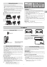
Auto Restart Setting
The product was shipped with Auto Restart function in the off position.
Turn it on as required.
Remote Control A-B Selection
To separate using of remote control for each indoor unit in case of 2 air
conditioner are installed near.
Remote Control B Setup.
1. Press [RESET] button on the indoor unit to turn the air conditioner ON.
2. Point the remote control at the indoor unit.
3. Push and hold [CHECK] button on the Remote Control by the tip of the
pencil. “00” will be shown on the display (Picture
1
).
4. Press [MODE] during pushing [CHECK]. “B” will show on the display
and “00” will disappear and the air conditioner will turn OFF. The Remote
Control B is memorized (Picture
2
).
Note : 1. Repeat above step to reset Remote Control to be A.
2. Remote Control A have not “A” display.
3. Default setting of Remote Control from factory is A.
• Check the
fl
are nut connections
for the gas leak with a gas leak
detector or soap water.
This product is designed so that, after a power failure, it can restart automatically
in the same operating mode as before the power failure.
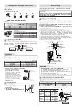
Stripping length of the connecting cable
Model
RAS-077, 107,
137SKV-E7
RAS-167SKV-E7
Power source
50Hz, 220 – 240 V Single phase
60Hz, 220 – 230 V Single phase
Maximum running current
8A
10A
Plug socket & fuse rating
10A
16A
Power cord
H07RN-F or 60245 IEC66 (1.5 mm
2
or more)
NOTE
: Connecting cable
• Wire type : More than H07RN-F or 60245 IEC66 (1.5 mm
2
or more)
• Wrong wiring connection may cause some electrical parts burn out.
• Be sure to comply with local cords on running the wire from indoor unit
to outdoor unit (size of wire and wiring method, etc.).
• Every wire must be connected
fi
rmly.
• This installation fuse (16A) must be used for the power supply line of
this air conditioner.
• If incorrect or incomplete wiring is carried out, it will cause an ignition or
smoke.
• Prepare the power supply for exclusive use with the air conditioner.
• This product can be connected to the mains.
Connection to
fi
xed wiring: A switch which disconnects all poles and
has a contact separation of at least 3 mm must be incorporated in the
fi
xed wiring.
CAUTION
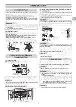
Check places for
the indoor unit.
Check places for
the outdoor unit.
Information
To switch the TEST RUN (COOL)
mode, press [RESET] button for
10 seconds. (The beeper will make
a short beep.)
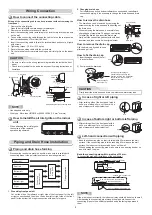
Wiring Connection
1. Remove the valve cover from the outdoor unit.
2. Connect the connecting cable to the terminals as identi
fi
ed with their
respective matched numbers on the terminal block of indoor and outdoor
unit.
3. When connecting the connecting cable to the outdoor unit terminals, make
a loop as shown in the installation diagram of indoor and outdoor unit to
prevent water coming in the outdoor unit.
4. Insulate the unused cords (conductors) from any water coming in the
outdoor unit. Proceed them so that they do not touch any electrical or
metal parts.
• When two indoor units are installed in the same room or adjacent two
rooms, if operating a unit, two units may receive the remote control signal
simultaneously and operate. In this case, the operation can be preserved
by setting either one remote control to B setting. (Both are set to A setting
in factory shipment.)
• The remote control signal is not received when the settings of indoor unit
and remote control are different.
• There is no relation between A setting/B setting and A room/B room when
connecting the piping and cables.
How to set the Auto Restart
1. Press and hold the [RESET] button on the indoor unit for 3 seconds to
set the operation. (3 beep sound and OPERATION lamp blink 5 time/sec
for 5 seconds)
2. Press and hold the [RESET] button on the indoor unit for 3 seconds to
cancel the operation. (3 beep sound but OPERATION lamp does not
blink)
• In case of ON timer or OFF timer are set, AUTO RESTART
OPERATION does not activate.
RESET
RESET button
1
2
RAS-077, 107, 137SAV-E6
RAS-167SAV-E5
/ 1
/
1
/ 1
/
1
Connecting cable
Power cord
Earth line
Earth line
Connecting cable
Terminal block
Power cord
Connecting cable
Power cord
Earth line
Earth line
Connecting cable
Terminal block
Power cord
Summary of Contents for RAS-077SAV-E6
Page 10: ...1115551127 ...


