background image

 
Menu Function                                                                           

 
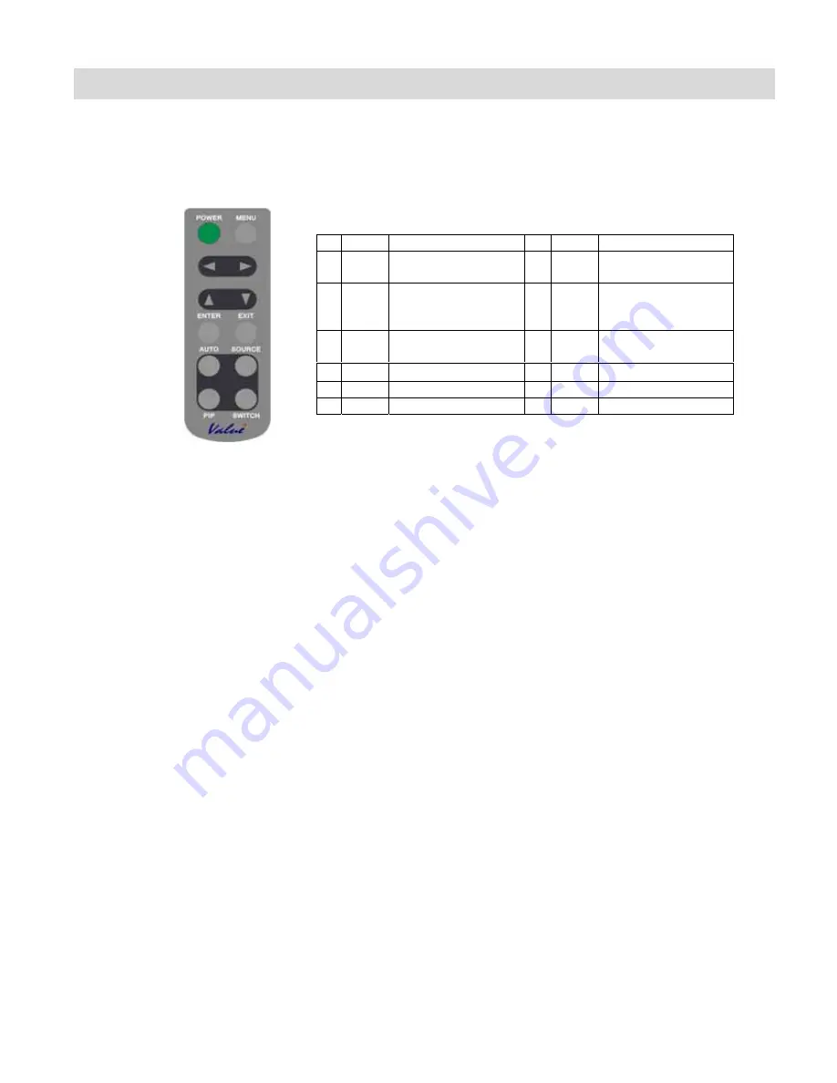
Display Menu, pictures or various functions can be set with the buttons on the remote control. 
The following are summary of Menu Function. For details, please see to refer pages. 


Function of Remote control


No.

Key

Descriptions No.

Key

Descriptions 

1  Power Power on / Power off

7

Menu 

OSD control menu 

button 

2 Auto

Adjust clock, phase, 

H position and V 

position Automatically

8

Exit

One Level up 

3 Source

Input source 

selection 

9


Menu Up 

PIP

Picture in picture 

10


Menu Down 

5  Switch

PIP picture switch 

11

Y


Menu Left 

6 Enter

Activate 

selection  12

Z


Menu Right 


Remote control Keypad lock/unlock control: 

Use remote control push buttons: 
Lock: Press (Enter)=> (Enter)=> (Exit)=> (Exit)=> (Enter)=> (Exit) sequently and OSD will be locked. 
Unlock: When OSD be locked. Press (Enter)=> (Enter)=> (Exit)=> (Exit)=> (Enter)=> (Exit) sequently 
and OSD will be unlocked. 


18

Summary of Contents for P47LSA

Page 1: ...OWNER S MANUAL LCD Monitor P47LSA 1 ...

Page 2: ...nctions of Controls Remote control 12 Battery Installation 12 Supplied Accessories 13 Connection 14 Installation 15 For inquiries 15 Dimension 16 Power On Off 17 Main power switch 17 POWER button on the Remote control 17 Menu Function 18 Function of Remote control 18 Remote control keypad lock unlock control 18 Menu display chart 19 A Guide to Simple Problem Solving 24 Factory default setting 24 I...

Page 3: ... Figure Meaning of Figure Shows prohibited matter The contents are written or shown by picture at inside or near the figure Shows instructed matter The contents are written or shown by picture at inside or near the figure Shows caution The contents are written or shown by picture at inside or near the figure The figure on the left shows caution for High tension current Prohibition instruction High...

Page 4: ... unit by the remote control press the main power switch again and light the power standby on indicator When turning off the unit by pressing the POWER button on the remote control the main power of the unit is not turned off To disconnect the unit completely from power supply remove the power plug from the outlet If the power cord or plug is damaged or becomes hot turn off the main power switch of...

Page 5: ...tal or liquid when putting vase glass or cosmetics get into the unit it may cause fire or electrical shock If any heavy object placed on the unit it may fall down and cause injury When installing the unit have your dealer arrange for professional installations If the installation work is not correct it may cause injury Use 5 Never repair modify or disassemble the unit by yourself It may cause a fi...

Page 6: ...his dust may cause a fire due to reduced insulation of the plug Caution Cleaning Installation Do not install the unit where humidity is high If the unit is installed in direct sunlight a closed car or near a stove it may cause overheating or electrical shock Also the cabinet or other parts may distort or be damaged and electrical shock may result Do not install the unit where it is exposed to humi...

Page 7: ... if the power cord is damaged injury may occur by the unit falling down When unpacking or carrying the unit at least two people are needed Make sure the units upright Do not carry the unit with the screen facing up or down Handle the unit so as not to jolt the unit Do not overload outlets or cables beyond their capacity Do not use extension cords Electrical shock or fire may result Use 7 Do not pu...

Page 8: ... The glass of the LCD panel may break and cause injury If the screen glass breaks crystalline liquid leakage may occur Do not touch crystalline liquid If leaked liquid gets into your eyes or comes in contact with your skin it may hurt your eyes or your skin If leaked liquid gets into your eyes or mouth or comes in contact with your skin rinse the contacted area with clean water immediately and con...

Page 9: ...in the owner s manual Toshiba is not liable for any damage caused by misuse or malfunction through simultaneous use of this product and the connected equipment or software Toshiba is not liable for any damage caused by neglect of the instructions described about the installation stand in the owner s manual Toshiba is not liable for any damage caused by improper installation Features High resolutio...

Page 10: ...r requirement AC100 240V 50 60Hz 250W P47LSA Size 1138 80 x 682 38 x 126 4 mm 44 83 x 26 87 x 4 98 inches Weight P47LSA 52kg 114 64 lbs Accessories Owner s Manual Power RGB DVI D VGA RS232 cables Remote control Video Input Terminal Video Composite Input RCA Level Video Input 1 0Vp p composite video PAL NTSC Y C Input Terminal Y C separate Inputs Mini Din 4pins terminals Level Luminance 1 0Vp p Col...

Page 11: ...enu Right 4 Menu Left 5 Menu Down 6 Menu Up 7 Exit OSD control Menu button Power ON Stand by Indicator Remote Control Receiver Light sensor LCD Screen Side Keypad lock unlock control Use control push buttons at side Lock Press and at the same time and OSD will be locked Unlock Press and at the same time again and OSD will be unlocked Back ...

Page 12: ...ct 3 Place back cover and slide it is as 3 in the picture 4 Used battery need to follow the city rule to discard 5 Avoid keeping used old battery inside the remote control causing leakage of internal liquid resulting metal rust or fatal damage to the remote control hand unit CAUTION Risk of explosion if battery is replaced by an incorrect type Dispose of used battery according to the instructions ...

Page 13: ...ase check all are supplied Owner s Manual x 1 Remote Control x 1 VGA Cable x 1 1 8M OWNER S MANUAL LCD Monitor P47LSA RCA Cable x 1 1 8M Power Cord x 1 1 8M DVI D Cablex1 1 8M S Video Cable x 1 1 8M Component Cable x 1 1 8M 13 ...

Page 14: ...EO IN RCA NTSC PAL S VIDEO S Video Mini Din 4pin NTSC PAL YUV Y Pb Cb Pr Cr Component Mini Din 8 pin NTSC PAL Suitable signal is automatically selected RGB INPUT You can select RGB input from 2 terminals below Terminal Type Suitable signals RGB ANALOG D Sub 15 pin RGB ANALOG RGB DIGITAL DVI D 24 pin RGB DIGITAL 14 ...

Page 15: ...or to install LCD monitor Where to install the LCD monitor If the wall is made of thin plywood or plastered board it cannot hold the weight The chart below shows adaptable anchors for each material Please check well the structure and strength of the place to install and choose the best method for safety Adaptable anchors screws for each material Material Anchor Plastered board Plywood board Imposs...

Page 16: ...Dimension 16 ...

Page 17: ...t Mode LED indicator Power on Green Power Standby Yellow No signal Orange No power input No LED If Main power switch is not On you cannot turn on the unit by the POWER Standby On button POWER button on the remote control About the control by the POWER button on the unit side on refer to page 12 POWER button on the Remote control You can switch Power standby Yellow to On Green by pressing this butt...

Page 18: ...tton 2 Auto Adjust clock phase H position and V position Automatically 8 Exit One Level up 3 Source Input source selection 9 Menu Up 4 PIP Picture in picture 10 Menu Down 5 Switch PIP picture switch 11 Y Menu Left 6 Enter Activate selection 12 Z Menu Right Remote control Keypad lock unlock control Use remote control push buttons Lock Press Enter Enter Exit Exit Enter Exit sequently and OSD will be...

Page 19: ... PAP PIP Size Small Med Large Vertical Horizontal IMAGE Scaling 1 1 Fill Aspect Panor Auto Adjust Select Phase Clock COLOR Color Temperature User 3200K 5400K 6500K 9300K Gamma Correction Off 2 2 2 4 Red Green Blue Display PIP input selection OSD Position Vertical Horizontal Blend Time Out OSD Zoom On Off Langue English Select Others Factory Reset Yes No Light sensor On Off Light sensor value OSD V...

Page 20: ...highlighted To change or adjust the value Up Down or Left Right key will do for selection Normally Up Down are for adjustment item selection and Left Right are for value change As for the adjustment RGB PC signal Y Cb Cr signal or Video signal some adjustments are different from the one to the other by different input selection When going out from this mode for example above right picture in Flesh...

Page 21: ... picture The color temperature adjustment is done by the adjustment of each individual color thus by the selection of the color temperature Red Green and Blue value changes When color matching necessary for multiple displays at the same place by using these value controls there is a possibility to color match It is recommended to use User position for the adjustment thus when other color temperatu...

Page 22: ...ted and highlighted The pictures below show S Video below the PIP icon this is indicating the PIP small picture input that was selected At the below right the small indication below the Y C icon IVP which stands for Input Video Processor indicated and when RGB is selected this will change to IGP Input Graphic Processor In this picture above left PIP Control page is present and this is somewhat dou...

Page 23: ... of this light sensor is to check the environment light level If the area was dark then display Brightness may not be so much brighter compared to the bright noon time Light sensor selection is to make ON OFF if this function is necessary or not Light Sensor Value adjustment works as to control the picture brightness when after the light sensor worked Setting this value higher will result the inte...

Page 24: ...aiming at the remote control sensor 11 The picture color is pale or not clear Check the picture quality adjustment 19 If you are using YUV terminals make sure cables are correctly connected N A Factory default setting Item Default Item Default Power switch Off Color temp User Brightness 80 Red 225 Contrast 50 Green 225 Hue 0 Blue 225 Saturation 50 Language English Flesh tone Off Light Sensor Off G...

Page 25: ...T 720x400 31 469 70 087 28 322 N P 900 108 45 720 27 449 2 35 400 12 O 19 UXGA50 1600x1200 62 50 50 00 135 00 N N 2160 192 304 1600 64 1250 3 46 1200 1 O O 20 UXGA60 1600x1200 75 00 60 00 162 00 N N 2160 192 304 1600 64 1250 3 46 1200 1 O O 21 640x480 35 000 66 667 30 240 N N 864 64 96 640 64 525 3 39 480 3 O O 22 832x624 49 725 74 500 57 283 N N 1152 64 224 832 32 667 3 39 624 1 O O 23 Macintosh ...

Page 26: ...ration is subject to the following two conditions 1 this device may not cause harmful interference and 2 this device must accept any interference received including interference that may cause undesired operation CE MARKING DECLARATION OF CONFORMITY This LCD Touch Monitor complies with the requirements of related European standards which include Emission EN 55022 EN 61000 3 2 EN 61000 3 3 Immunity...

Reviews: