background image

Toshiba

– 19 –

SMMS 4-way Air Discharge Cassette Type

Installation Manual

„

Wire connection

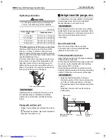
REQUIREMENT

• Be sure to connect the wires matching the terminal numbers. Incorrect connection causes a trouble.
• Be sure to pass the wires through the bushing of wiring connection port of the indoor unit.
• Keep a margin (Approx. 100mm) on a wire to hang down the electric parts box at servicing, etc.
• The low-voltage circuit is provided for the remote controller. (Do not connect the high-voltage circuit)
• Make a loop on the wire for margin of the length so that the electric parts box can be taken out during 

servicing.

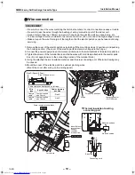
1. Remove the cover of the electric parts box by taking off the mounting screws (2 positions) and pushing 

the hooking section. (The cover of the electric parts box remains hanged to the hinge.)

2. Connect the power supply wire and remote controller wire to the terminal block of the electric parts box.
3. Tighten the screws of the terminal block, and fix the wires with cord clamp attached to the electric parts 

box. (Do not apply tension to the connecting section of the terminal block.)

4. Using the attached thermal insulation material, seal the pipe connecting port. Otherwise, dewing may 

be caused.

5. Mount the cover of the electric parts box without pinching wires.

(Mount the cover after wiring on the ceiling panel.)

L N

U

1

U

2

A B

R

(L)

10

10

50

70

S

(N)

Hinge

Screws in 2 positions

Louver connector 

(CN510:White)

Side D (Space: 8.5mm)

Side C (Space: 4mm)

* Cable clamp can be attached on left side.

Wire 

type

Specification

Cable clamping 

position

Cabtyre 

cable

3-core stranded 

wire 2.5mm²

Side D

Cabtyre 

cable

4-core stranded 

wire 1.5mm²

Side C

Adhered surface

Notched section

Thermal insulation to wiring 
connecting port

Power supply terminal block

Indoor/Outdoor 

inter-unit wire/

Remote 

controller 

terminal block

Cord clamp

Earth line

Connecting cord

19-EN

+00EH99863501_6L_SMMS_4-way_IM1_printOnly.book  Page 19  Thursday, September 11, 2008  9:29 AM

Summary of Contents for MMU-AP0092H

Page 1: ...MU AP0362H MMU AP0482H MMU AP0562H For commercial use Pour usage commercial Nur für gewerbliche Nutzung Per uso commerciale Para uso comercial Para uso comercial Installation Manual Installation Manual 1 English Manuel d installation 37 Français Installations handbuch 73 Deutsch Manuale di installazione 109 Italiano Manual de instalación 145 Español Manual de Instalação 181 Português ...

Page 2: ...8 10 MAINTENANCE 30 11 TROUBLE SHOOTING 33 Please read this Installation Manual carefully before installing the Air Conditioner This Manual describes the installation method of the indoor unit For installation of the outdoor unit follow the Installation Manual attached to the outdoor unit ADOPTION OF NEW REFRIGERANT This Air Conditioner is a new type which adopts a new refrigerant HFC R410A instea...

Page 3: ... a wireless remote controller and adjust corner caps with a receiver section Part name Q ty Shape Usage Installation Manual 2 These manual Be sure to hand over to customers Heat insulating pipe 2 For heat insulation of pipe connecting section Installation pattern 1 For confirmation of ceiling opening and indoor unit position Installation gauge For positioning of ceiling position Washer 4 For hangi...

Page 4: ...ure in the refrigeration cycle becomes abnormally high and it resultingly causes pipe burst and injuries on persons Perform installation work properly according to the Installation Manual Inappropriate installation may result in water leakage electric shock or fire When the air conditioner is installed in a small room provide appropriate measures to ensure that the concentration of refrigerant lea...

Page 5: ... connecting sections of charging port of the main unit and installation tools are changed from those for the conventional refrigerant Accordingly the exclusive tools are required for the new refrigerant R410A For connecting pipes use new and clean piping designed for R410A and please care so that water or dust does not enter To Disconnect the Appliance from Main Power Supply This appliance must be...

Page 6: ...eat exchanger and resin part turbo fan in the indoor unit may reduce the performance generate mist or dew drop or deform or damage resin parts Place where organic solvent is used nearby Place close to a machine generating high frequency Place where the discharged air blows directly into the window of the neighbor house Outdoor unit Place where noise of the outdoor unit is easily transmitted When i...

Page 7: ...ly on all the positions of the indoor unit which come to contact with high humidity atmosphere REQUIREMENT When the humidity inside the ceiling seems to be higher than 80 attach a heat insulator to the side top surface of the indoor unit Use a heat insulator that is 10mm or more thick Ceiling height When the height of the ceiling exceeds the distance of the item Standard 4 way in Table on the next...

Page 8: ... satisfactory heating due to location place of the indoor unit or the structure of the room the detection temperature of heating can be raised Discharge direction As shown in the figure below air discharge directions can be selected according to the shape of the room and the location of the indoor unit installation Use a shielding plate kit sold separately to change discharge directions Discharge ...

Page 9: ...P0092H to AP0122H 256 Ø6 4 Ø9 5 120 AP0242H to AP0302H 256 Ø9 5 Ø15 9 120 AP0152H to AP0182H 256 Ø6 4 Ø12 7 120 AP0362H to AP0562H 319 Ø9 5 Ø15 9 183 Ceiling bottom surface Knockout square hole for divide duct For Ø150 Knockout square hole for divide duct For Ø150 840 Unit external dimension Ceiling bottom surface Electric parts box Refrigerant pipe connecting port Liquid B Refrigerant pipe connec...

Page 10: ...e four holes in the installation pattern to the panel fixing screws of the indoor unit When hanging a ceiling open the ceiling along the outside dimensions of the installation pattern Treatment of ceiling The ceiling differs according to structure of building For details consult your constructor or interior finish contractor In the process after the ceiling board has been removed it is important t...

Page 11: ...e installation gauge is printed on the gauge REQUIREMENT Before installation of the indoor unit be sure to remove the cushion for transportation between the fan and the bell mouth Running the unit without removing the cushion may damage the fan motor Hanging bolt Level vial Hanging bracket 12 Washer Accessory To prevent the bolt from falling off for safety be sure to set it just under the hanging ...

Page 12: ... wired remote controller follow the Installation Manual attached with the remote controller Pull out the remote controller cord together with the refrigerant pipe or drain pipe Be sure to pass the remote controller cord through upper side of the refrigerant pipe and drain pipe Do not leave the remote controller at a place exposed to the direct sunlight and near a stove In case of wireless type The...

Page 13: ...erval of 1 5 to 2m in order to prevent waving Set the collective piping as shown in the below figure Be sure not to apply force to the connecting part of the drain pipe The hard vinyl chloride pipe cannot be directly connected to the drain pipe connecting port of the indoor unit For connection with the drain pipe connecting port be sure to use fix the attached flexible hose with the hose band othe...

Page 14: ...heck that water drain is properly performed and water does not leak from the connecting part of the pipes Be sure to check draining also when installed in heating period Using a pitcher or hose pour water 1500 to 2000cc into the discharge port before installation of the ceiling panel Pour water gradually so that water does not spread on the motor of the drain pump CAUTION Pour water gently so that...

Page 15: ... figure cover the flexible hose and hose band with the attached heat insulator up to the bottom of the indoor unit without gap Cover the drain pipe seamlessly with a heat insulator to be procured locally so that it overlaps with the attached heat insulator of the drain connecting section Direct the slits and seams of the heat insulator upward to avoid water leakage S N R L Pull out connector CN34 ...

Page 16: ...door unit For details refer to the Installation Manual attached to the outdoor unit Flaring Cut the pipe with a pipe cutter Remove burrs completely Remaining burrs may cause gas leakage Insert a flare nut into the pipe and flare the pipe As the flaring sizes of R410A differ from those of refrigerant R22 the flare tools newly manufactured for R410A are recommended However the conventional tools can...

Page 17: ...e Installation Manual attached to the outdoor unit REQUIREMENT Do not supply power to the indoor unit until the airtight test and vacuuming are completed If the indoor unit is powered on the pulse motor valve is fully closed which extends the time for vacuuming Open the valve fully Open the valve of the outdoor unit fully For details refer to the Installation Manual attached to the outdoor unit Th...

Page 18: ...e high temperature part of the pipe The coating may melt resulting in an accident After connecting wires to the terminal blocks provide a trap and fix wires with the cord clamp Run the refrigerant piping line and control wiring line in the same line Do not turn on the power of the indoor unit until vacuuming of the refrigerant pipes completes Power supply wire and communication wires specification...

Page 19: ...oor units and outdoor unit 2 core shield wire Wire size Up to 1000m 1 25 mm Up to 2000m 2 0 mm Central control line wiring 2 core shield wire Wire size Up to 1000m 1 25 mm Up to 2000m 2 0 mm Remote controller wiring remote controller inter unit wiring Wire size 0 5mm to 2 0mm Total wire length of remote controller wiring and remote controller inter unit wiring L L1 L2 Ln In case of wired type only...

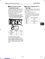
Page 20: ...nd remote controller wire to the terminal block of the electric parts box 3 Tighten the screws of the terminal block and fix the wires with cord clamp attached to the electric parts box Do not apply tension to the connecting section of the terminal block 4 Using the attached thermal insulation material seal the pipe connecting port Otherwise dewing may be caused 5 Mount the cover of the electric p...

Page 21: ...rminal block Remote controller unit 220 240V 50Hz 220V 60Hz 380V 415V 50Hz 380V 60Hz U1 U2 U1 U2 U3 U4 L1 L2 L3 N U5 U6 L N A B A B 380V 415V 50Hz 380V 60Hz U1 U2 U3 U4 L1 L2 L3 N U5 U6 U1 U2 L N A B A B U1 U2 L N A B A B U1 U2 L N A B Outdoor Power supply Earth terminal Earth terminal Outdoor Power supply Earth leakage breaker Earth leakage breaker Header outdoor unit Follower outdoor unit Contro...

Page 22: ...stallation Manual supplied with the outdoor unit Wiring on the ceiling panel According to the Installation Manual of the ceiling panel connect the connector 20P White of the ceiling panel to the connector CN510 White on P C board of the electric parts box R L S N terminal block for power supply Indoor P C board Faston connection Earth screw Earth screw Power supply Attached wire Power supply Attac...

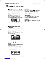
Page 23: ...ting differs from that on the former types of remote controller RBC AMT21E AMT31E The number of CODE No has increased Procedure 1 Push button and TEMP button simultaneously for at least 4 seconds After a while the display flashes as shown in the figure Confirm that the CODE No is 10 If the CODE No is not 10 push button to erase the display content and repeat the procedure from the beginning No ope...

Page 24: ...y content disappears and the air conditioner enters the normal stop mode While is flashing no operation of the remote controller is accepted When installing separately sold filters Be sure to make ceiling setting when installing separately sold filters Separately sold filters cannot be installed in an indoor unit on a high ceiling Follow to the basic operation procedure 1 2 3 4 5 6 For the CODE No...

Page 25: ...gs To return the DIP switch settings to the factory settings set SW501 1 and SW501 2 to OFF connect a separately sold wired remote controller and then set the data of CODE No 5d to 0000 in When installing separately sold filters on this page Change of lighting time of filter sign According to the installation condition the lighting time of the filter sign Notification of filter cleaning can be cha...

Page 26: ...the setting The display state changes from flashing to lighting and the setting is fixed 6 Push button to end the setting When the cold draft position is selected ceiling contamination is less reduced How to set up swing type 1 Push for at least four seconds when the air conditioner is not working flashes Indicates CODE No F0 2 Select an indoor unit to be set by pushing left side of the button Eac...

Page 27: ...not working flashes Indicates CODE No F1 2 Select an indoor unit to be set by pushing left side of the button Each time you push the button unit numbers change as follows The fan of the selected unit runs and the louvers start swinging 3 Select a louver you want to lock by pushing TEMP buttons 4 Select the wind direction of the louver you do not want to swing by pushing TIME buttons When 4 or 5 is...

Page 28: ...unit wires from the remote controller terminal blocks A B of the indoor unit connected with a remote controller to the remote controller terminal blocks A B of the other indoor unit Non polarity For address setup refer to the Installation Manual attached to the outdoor unit Remote controller sensor The temperature sensor of the indoor unit senses room temperature usually Set the remote controller ...

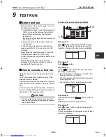
Page 29: ...r to the attached Owner s Manual A forced test run can be executed in the following procedure even if the operation stops by thermo OFF In order to prevent a serial operation the forced test run is released after 60 minutes have passed and returns to the usual operation CAUTION Do not use the forced test run for cases other than the test run because it applies an excessive load to the devices In c...

Page 30: ...ash repeat procedures 3 to 5 Procedure 7 Upon completion of the test run push ON OFF button to stop operation Overview of test run operations using the wireless remote controller Cooling test run ON OFF 18 C 19 C 18 C 19 C 18 C 19 C 18 C test run ON OFF Heating test run ON OFF 30 C 29 C 30 C 29 C 30 C 29 C 30 C test run ON OFF Cooling test run Heating test run Set the temperature to 18 C with the ...

Page 31: ... Stop the operation by remote controller 2 Dismount the air filter Use a vacuum cleaner to remove dust from the filters or wash them with water After rinsing the air filters with water dry them in the shade Set the air filter into the air conditioner Clean the panel and air filter with water Wipe down the panel and air filter with a sponge or towel moistened with a kitchen detergent Do not use any...

Page 32: ...ly to ensure efficient operation of the air conditioner When the air conditioner is operated for a long time periodic maintenance once a year is recommended Furthermore regularly check the outdoor unit for rust and scratches and remove them or apply rustproof treatment if necessary As a general rule when an indoor unit is operated for 8 hours or more daily clean the indoor unit and outdoor unit at...

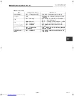
Page 33: ... water when it is contaminated Replace it when it is damaged Fan Vibration balance Dust dirt appearance Replace the fan when vibration or balance is terrible Brush or wash the fan when it is contaminated Air inlet outlet grilles Dust dirt scratches Fix or replace them when they are deformed or damaged Drain pan Dust dirt clogging drain contamination Clean the drain pan and check the downward slope...

Page 34: ...ory can be confirmed from both operating status and stop status Procedure 1 When pushing and buttons at the same time for 4 seconds or more the following display appears If Service check is displayed the mode enters in the trouble history mode 01 Order of trouble history is displayed in CODE No window Check code is displayed in CHECK window Indoor unit address in which an error occurred is display...

Page 35: ...ay of receiving unit Auxiliary code Operation Timer Ready Flash E01 Communication error between indoor and remote controller Detected at remote controller side Remote controller E02 Remote controller transmission error Remote controller E03 97 Communication error between indoor and remote controller Detected at indoor side Indoor E04 04 Communication circuit error between indoor outdoor Detected a...

Page 36: ... level down detective protection I F H08 H08 01 TK1 sensor error 02 TK2 sensor error 03 TK3 sensor error 04 TK4 sensor error d4 Oil level detective temp sensor error I F H14 H14 44 Comp 2 case thermo operation I F H16 H16 01 TK1 oil circuit system error 02 TK2 oil circuit system error 03 TK3 oil circuit system error 04 TK4 oil circuit system error d7 Oil level detective circuit error Magnet switch...

Page 37: ...sor error E Vdc output error 1A ALT Outdoor fan IPDU error IPDU P26 P26 01 Comp 1 side 02 Comp 2 side 14 ALT G TR short protection error IPDU P29 P29 01 Comp 1 side 02 Comp 2 side 16 ALT Comp position detective circuit system error IPDU P31 P31 47 ALT Other indoor unit error Group terminal unit error Indoor b7 By alarm device ALT Error in indoor group AI NET 97 AI NET communication system error AI...

Page 38: ... 217 MEMO ...

Page 39: ... air conditioners is 0 3kg m NOTE 1 If there are 2 or more refrigerating systems in a single refrigerating device the amounts of refrigerant should be as charged in each independent device For the amount of charge in this example The possible amount of leaked refrigerant gas in rooms A B and C is 10kg The possible amount of leaked refrigerant gas in rooms D E and F is 15kg NOTE 2 The standards for...

Page 40: ...CHANGE STANDARD 0000 HIGH CEILING 1 0001 HIGH CEILING 3 0003 Have you changed lighting time of filter sign If not fill check mark in NO CHANGE and fill check mark in ITEM if changed respectively For check method refer to Applicable controls in this sheet Filter sign lighting time Item code 01 NO CHANGE NONE 0000 150H 0001 2500H 0002 5000H 0003 10000H 0004 Filter sign lighting time Item code 01 NO ...

Reviews: