


SMMS High-Wall Type
Installation Manual
– 28 –
EN
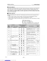
E23
E23
—
Sending error in communication
between outdoor units
I/F
E25
E25
—
Duplicated follower outdoor addresses
I/F
E26
E26
No. of outdoor units which
received signal normally
Decrease of No. of connected outdoor
units
I/F
E28
E28 Detected outdoor unit number
Follower outdoor unit error
I/F
E31
E31
01: IPDU1 error
02: IPDU2 error
03: IPDU1, 2 error
04: Fan IPDU error
05: IPDU + Fan IPDU error
06: IPDU2 + Fan IPDU error
07: All IPDU error
IPDU communication error
I/F
F01
—
—
ALT
Indoor TCJ sensor error
Indoor
F02
—
—
ALT
Indoor TC2 sensor error
Indoor
F03
—
—
ALT
Indoor TC1 sensor error
Indoor
F04
F04
—
ALT
TD1 sensor error
I/F
F05
F05
—
ALT
TD2 sensor error
I/F
F06
F06
—
ALT
TE1 sensor error
I/F
F07
F07
—
ALT
TL sensor error
I/F
F08
F08
—
ALT
TO sensor error
I/F
F10
—
—
ALT
Indoor TA sensor error
Indoor
F12
F12
—
ALT
TS1 sensor error
I/F
F13
F13
01: Comp. 1 side
02: Comp. 2 side
ALT
TH sensor error
IPDU
F15
F15
—
ALT
Outdoor temp. sensor miscabling (TE,
TL)
I/F
F16
F16
—
ALT
Outdoor pressure sensor miscabling
(Pd, Ps)
I/F
F23
F23
—
ALT
Ps sensor error
I/F
F24
F24
—
ALT
Pd sensor error
I/F
F29
—
—
SIM
Indoor other error
Indoor
F31
F31
—
SIM
Indoor EEPROM error
I/F
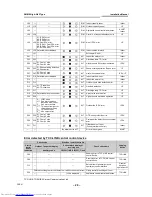
H01
H01
01: Comp. 1 side
02: Comp. 2 side
Compressor break down
IPDU
H02
H02
01: Comp. 1 side
02: Comp. 2 side
Magnet switch error
Overcurrent relay operation
Compressor trouble (lock)
MG-SW
Overcurrent
relay
IPDU
H03
H03
01: Comp. 1 side
02: Comp. 2 side
Current detect circuit system error
IPDU
H04
H04
—
Comp 1 case thermo operation
I/F
H06
H06
—
Low pressure protective operation
I/F
H07
H07
—
Oil level down detective protection
I/F
H08
H08
01: TK1 sensor error
02: TK2 sensor error
03: TK3 sensor error
04: TK4 sensor error
Oil level detective temp sensor error
I/F
H14
H14
—
Comp 2 case thermo operation
I/F
H16
H16
01: TK1 oil circuit system error
02: TK2 oil circuit system error
03: TK3 oil circuit system error
04: TK4 oil circuit system error
Oil level detective circuit error
Magnet switch error
Overcurrent relay operation
I/F
MG-SW
Overcurrent
relay
L03
—
—
SIM
Indoor centre unit duplicated
Indoor
L04
L04
—
SIM
Outdoor line address duplicated
I/F
L05
—
—
SIM
Duplicated indoor units with priority
(Displayed in indoor unit with priority)
I/F
L06
L06 No. of indoor units with priority
SIM
Duplicated indoor units with priority
(Displayed in unit other than indoor unit
with priority)
I/F
L07
—
—
SIM
Group line in individual indoor unit
Indoor
L08
L08
—
SIM
Indoor group/Address unset
Indoor, I/F
28-EN