– 11 –
SMMS Floor Standing Type
Installation Manual
SMMS Floor Standing Type
Installation Manual
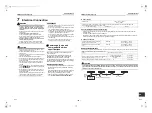
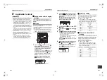
Wiring between indoor and outdoor units
NOTE
An outdoor unit connected with control wiring between indoor and outdoor units wire becomes automatically the
header unit.
▼
Wiring example
U1 U2
U1 U2 U3 U4
L1 L2 L3 N
U5 U6
L N
A B
A B
U1 U2 U3 U4
L1 L2 L3 N
U5 U6
U1 U2
L N
A B
A B
U1 U2
L N
A B
A B
U1 U2
L N
A B
Outdoor Power supply
380 V - 415 V ~, 50 Hz
380 V ~, 60 Hz
Circuit breaker,
Power switch
Remote controller
Indoor unit
Outdoor Power supply
380 V - 415 V ~, 50 Hz
380 V ~, 60 Hz
Remote controller
Remote controller
Indoor unit
Indoor unit
Indoor unit
Circuit breaker
Circuit breaker
Header outdoor
unit
Follower outdoor
unit
Control wiring between outdoor units
Control wiring between indoor and outdoor units
Control wiring between indoor units
Indoor power supply
220 V - 240 V ~, 50 Hz
220 V ~, 60 Hz
Earth
Earth
Earth
Earth
Group control
Pull box
Pull box
Pull box
Earth
terminal
Earth
terminal
Wire connection
REQUIREMENT
• Connect the wires matching the terminal numbers.
Incorrect connection causes a trouble.
• Pass the wires through the bushing of wire connection
holes of the indoor unit.
• Keep a margin (Approx. 100 mm) on a wire to hang
down the electrical control box at servicing or other
purpose.
• The low-voltage circuit is provided for the remote
controller. (Do not connect the high-voltage circuit)
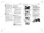
<How to remove the electrical control box cover>
• AP015 to AP027 models
Take off screws (1) and (2) at this side of the
electrical control box and remove the drip-proof
cover.
Take off screws (3) and (4) at front side of the
electrical control box and remove the electrical
control box cover.
• AP036 to AP056 models
Take off screws (3) and (4) at front side of the
electrical control box and remove the cover of the
electrical control box.
(The drip-proof cover is provided to AP015 to AP027
models only.)
<Wiring>
• Draw the wire into the control wire hole (knockout
hole).
• As shown in the figure, set a trap and fix the wire with
a cord clamp.
Do no apply tension on the connecting part of the
terminal block.
• Be sure to mount cover of the electrical control box
and the drip-proof cover.
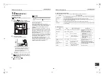
Remote controller wiring
Strip off approx. 9 mm the wire to be connected.
▼
Wiring diagram
Address setup
Set up the addresses as per the Installation Manual
supplied with the outdoor unit.
(1)
(2)
(3)
(4)
Electrical control box
Control wire
hole
Drip-proof cover
(AP015 to AP027
only)
Electrical control
box cover
R
S
R(L) S(N)
U
1
U
2
A B
N
L
B
A
Cord clamp
Electrical
control box
Power supply wire
Indoor / Outdoor control
wire / Remote controller
terminal block
Power supply
terminal block
Control wire between
indoor and outdoor units
R
(L)
S
(N)
10
10
50
70
Earth line
Power supply wire
A
B
A
B
Terminal block
Remote
controller
unit
Terminal block for
remote controller wiring
of indoor unit
Remote controller wire
(Locally procured)
21-EN
22-EN
+00EH99880501_01EN.book Page 11 Thursday, April 7, 2011 10:15 AM

