background image

- 17 -

7.

MODE SETTING BY ON SCREEN DISPLAY

Various settings can be controlled on the unit by using the on screen menu displayed on the
monitor. The contents once set are memorized in the SCENE files (A, B and C) even if the power
source is turned off. So it is unnecessary to set again when using the camera next time. When the
setting is performed, select the setting screen of the item to be set. A selected SCENE file
appears upper right on the setting screen.

7.1 Using the Screens

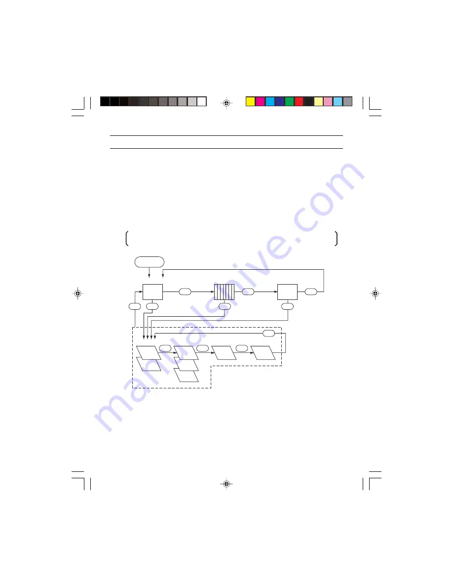
Each screen (video signal screen, color bar screen, index screen, setting screen or area
screen) can be displayed by using the [DISP], [PAGE], [MENU UP], [MENU DOWN], [DATA
UP], or [DATA DOWN] button on the rear side of the camera body.

A screen is selected when pressing the [PAGE] button after moving “

” on the screen

by the [MENU UP] or [MENU DOWN] button while the index screen is displayed.

DISP

POWER

ON

DISP

PAGE

PAGE

PAGE

PAGE

PAGE

AUTO

MANUAL

MANUAL

ATW

ONE PUSH  

WB

PAGE

PAGE

DISP

DISP

Video signal output

Color bar screen

Index menu

Menus

1. SENS

2. WHT BAL

3. PROCESS

4. OPTION

Summary of Contents for IK-1000 - Starlight Color Video Camera CCTV

Page 1: ...TMENT 11 6 OPERATION 13 7 MODE SETTING BY ON SCREEN DISPLAY 17 8 TROUBLESHOOTING 32 9 EXTERNAL VIEW 33 10 SPECIFICATIONS 34 Please read this manual thoroughly before use and keep it handy for future reference Record in space provided below the Model No and the Serial No as found on the label on the bottom of this unit Model No IK 1000 Serial No Retain this information for future reference ...

Page 2: ......

Page 3: ...it may be damaged 13 Lightning For added protection for this video product during a lightning storm or when it is left unattended and unused for long periods of time unplug it from the wall outlet and disconnect the power supply and cable system This will prevent damage to the video product due to lightning and power line surges If lightning occurs do not touch the unit or any connected cables in ...

Page 4: ...en tested and found to comply with the limits for a Class A digital device pursuant to Part 15 of the FCC Rules These limits are designed to provide reasonable protection against harmful interference when the equipment is operated in a commercial environment This equipment generates uses and can radiate radio frequency energy and if not installed and used in accordance with the instruction manual ...

Page 5: ...he location or the cable wiring If equipment originating radio waves such as cell phone comes close to the camera or the camera is installed near the relay antenna of such equipment noise may appear on the screen Moire When thin stripe patterns are shot stripe patterns that are not actually there moire may appear as interference stripes This is not a malfunction Operating ambient temperature and h...

Page 6: ...amera If the camera is installed in places where the strength of bearing it is insufficient secure the structure by reinforcement etc to bear the load If the reinforcement strength is insufficient the camera may drop causing personal injury and malfunction Handling of the protection cap Keep the protection cap away from children Children may put them into the mouth or swallow them accidentally Do ...

Page 7: ... Camera Support Fitting 2 IRIS terminal 4P 3 Imaging unit 6 C mount ring lock screw 7 C mount ring 4 Tripod setting hole 5 Iris selection switch For detailed dimensions refer to the external view on page 33 ...

Page 8: ...the function to be confirmed or changed on the setting screen i DATA UP AWB button Changes the setup contents of the function selected by the MENU UP DOWN button Also used to perform ONE PUSH WB o DATA DOWN button Changes the setup contents of the function selected by the MENU UP DOWN button 0 S VIDEO terminal Outputs Y brightness signal and C color signal 1 Camera Support Fitting Fitting to fix t...

Page 9: ...ount ring Install the C mount lens When attaching the camera to a tripod fasten the tripod to the camera tripod setting hole without sliding them from each other If not fixed securely the camera may drop causing personal injury Use a tripod screw that is between 4 mm and 8 mm in length 4 Tripod setting hole Used when fixing a camera to the tripod Cautions ...

Page 10: ...wer supply with the specifications described below Power supply voltage DC12V 10 Current rating 2 0 A or more Ripple voltage 50 mV p p or less Connector HR10A 7P 4S by HIROSE Electronics Co Ltd Pins 1 2 12V Pins 3 4 GND 1 Install the lens to the camera body For available lenses refer to the item 5 LENS ADJUSTMENT 2 Connect a coaxial cable from the VIDEO terminal to the video input terminal of the ...

Page 11: ...adjust SENS setting on the screen display menu For how to operate refer to the items 7 1 Selecting Screen and 7 3 Setting SENS Sensitivity How to adjust Video lens 1 Set the AUTO mode setting LEVEL to 0 Peak AVE to AVERAGE and AREA to PRESET 2 Select MANUAL mode for the SENS page of the screen display menu refer to 7 3 2 3 Set the lens to Average 4 While shooting an object exposed to light as equa...

Page 12: ...era resulting in malfunction and failure Cautions 5 3 How to Adjust Back Focus and field angle At factory setting back focus is set to its standard position However slight readjustments may be needed depending on the type of zoom lens Back focus is adjusted with the back focus adjustment ring at the top of the camera so that distance of the object can correctly meet the focus position of the lens ...

Page 13: ...er than the circuit gain AGC control and the sensitivity control with residual image far less than long term exposure This control is optimum with importance placed on the shooting of a moving subject Circuit gain AGC control Controls the sensitivity of EM CCD imaging element output in a subsequent circuit We suggest giving the highest possible priority to the electronic multiplication CMG control...

Page 14: ...of electronic multiplication CMG control the camera keeps the sensitivity of electronic multiplication CMG maximum and automatically activates the circuit gain AGC control to control the sensitivity automatically If a sufficient sensitivity is not yet obtained with the maximum circuit gain control the camera keeps the sensitivity of each of electronic multiplication CMG circuit and circuit gain AG...

Page 15: ...ature to adjust the white balance The camera automatically traces changes in color temperature to adjust the white balance If illumination condition is not good white balance may not be obtained Adjust the white balance by pressing the DATA UP button while shooting the white object in an area set on the ONE PUSH WB setting screen The accuracy is higher than that of ATW This is appropriate to shoot...

Page 16: ...to the item 7 4 WHT BAL White Balance Shoot a white object and adjust the white balance by adjusting R GAIN and B GAIN on the setting screen while confirming with a monitor or a vector scope Refer to the item 7 4 3 When Changing Settings in MANUAL manual white balance mode 6 3 SCENE files This unit has three SCENE files A B and C selectable according to the shooting conditions Select a scene set u...

Page 17: ...pears upper right on the setting screen 7 1 Using the Screens Each screen video signal screen color bar screen index screen setting screen or area screen can be displayed by using the DISP PAGE MENU UP MENU DOWN DATA UP or DATA DOWN button on the rear side of the camera body A screen is selected when pressing the PAGE button after moving on the screen by the MENU UP or MENU DOWN button while the i...

Page 18: ...N 255 262 5H OFF 2FLD time of long term 4FLD 6FLD 256FLD exposure CMG OFF CMG1 CMG2 Electronic multiplication OFF CMG10 gain GAIN OFF 1dB 2dB 18dB Circuit gain 0dB 2 WHT BAL ATW R PAINT 10 9 0 1 10 R offset of automatic 0 tracking white balance B PAINT 10 9 0 1 10 B offset of automatic 0 tracking white balance ONE R PAINT 10 9 0 1 10 R offset of one push 0 PUSH WB white balance B PAINT 10 9 0 1 10...

Page 19: ... by MENU UP DOWN Set by DATA UP DOWN 1 SENS FILE A SENS MODE AUTO MODE AUTO FLICKER OFF CMG MAX CMG5 AGC MAX OFF SS LONG MAX OFF LEVEL 0 PEAK AVE AVERAGE AREA PRESET A SENS mode AUTO MANUAL Display of SCENE file Flicker correction ON OFF Setting of maximum value of OFF CMG1 CMG2 CMG10 AUTO electronic multiplication Setting of maximum value of OFF 1dB 2dB 18dB AUTO circuit gain Setting of maximum v...

Page 20: ... of AUTO electronic multiplication Increase by DATA UP OFF CMG1 CMG10 Decrease by DATA DOWN At factory setting CMG1 to CMG10 are adjusted to the following gains CMG1 approx 2 times CMG2 approx 4 times CMG3 approx 8 times CMG4 approx 16 times CMG5 approx 32 times CMG6 approx 63 times CMG7 approx 125 times CMG8 approx 250 times CMG9 approx 500 times CMG10 approx 1000 times However aging may cause ch...

Page 21: ...DATA UP OFF 2FLD 256FLD Decrease by DATA DOWN 5 Changing the SENS level adjustment q Using the MENU UP or MENU DOWN button place on LEVEL w Using the DATA UP or DATA DOWN button set the SENS level Increase by DATA UP 100 0 100 Decrease by DATA DOWN 6 Changing brightness detection average value peak mode selection q Using the MENU UP or MENU DOWN button place on PEAK AVE w Using the DATA UP or DATA...

Page 22: ...button place on AREA w Using the DATA UP or DATA DOWN button select PEAK or AVERAGE PRESET A PRESET A PRESET B PRESET E PRESET F PRESET C PRESET G PRESET D PRESET B PRESET C PRESET D DATA UP DATA DOWN PRESET E PRESET F PRESET G Bold face on the diagram shows a detection area ...

Page 23: ...F 1dB 2dB 18dB 1 Changing electronic shutter speed q Using the MENU UP or MENU DOWN button place on MANUAL w Using the DATA UP or DATA DOWN button set the electronic shutter speed DATA UP OFF 1 100s 1 250s 1 500s 1 1000s 1 2000s DATA DOWN 2 Changing the setting of electronic multiplication gain q Using the MENU UP or MENU DOWN button place on CMG w Using DATA UP or DATA DOWN button set the electro...

Page 24: ...62 5H 255 262 5H OFF 2FLD 4FLD 6FLD 256FLD Electronic multiplication gain OFF CMG1 CMG2 CMG10 Circuit gain OFF 1dB 2dB 18dB 1 Changing the setting of Synchro Scan shutter speed q Using the MENU UP or MENU DOWN button place on SYNCHRO SCAN w Using the DATA UP or DATA DOWN button select the shutter speed DATA UP 9 262 5H 255 262 5H OFF 2FLD 256FLD DATA DOWN Long term exposure Electronic multiplicati...

Page 25: ...SCENE file WHT BAL mode ONE PUSH WB ATW MANUAL R RAINT offset adjustment 10 10 B RAINT offset adjustment 10 10 Electronic multiplication gain PRESET A PRESET B PRESET C PRESET D PRESET E PRESET F PRESET G 1 Changing R PAINT red offset q Using the MENU UP or MENU DOWN button place on R PAINT w Use the DATA UP or DATA DOWN button to make setting DATA UP 10 0 10 DATA DOWN Increase in red Decrease in ...

Page 26: ...ea q Using the MENU UP or MENU DOWN button place on AREA w Using the DATA UP or DATA DOWN button set the photometer area PRESET A Bold face on the diagram shows a detection area PRESET B PRESET E PRESET F PRESET C PRESET G PRESET D ...

Page 27: ...et adjustment 10 10 B RAINT offset adjustment 10 10 1 Changing R PAINT red offset q Using the MENU UP or MENU DOWN button place on R PAINT w Use the DATA UP or DATA DOWN button to make setting DATA UP 10 0 10 DATA DOWN Increase in red Decrease in red 2 Changing R PAINT blue offset q Using the MENU UP or MENU DOWN button place on B PAINT w Use the DATA UP or DATA DOWN button to make setting DATA UP...

Page 28: ...justment 110 109 0 204 Blue gain adjustment 250 249 0 256 1 Changing red gain q Using the MENU UP or MENU DOWN button place on R GAIN w Use the DATA UP or DATA DOWN button to make setting DATA UP 110 0 204 DATA DOWN Increase in red Decrease in red 2 Changing blue gain q Using the MENU UP or MENU DOWN button place on B GAIN w Use the DATA UP or DATA DOWN button to make setting DATA UP 250 0 256 DAT...

Page 29: ...NE file Gamma correction ON OFF Detail ON OFF 1 Changing ON OFF of gamma correction q Using the MENU UP or MENU DOWN button place on GAMMA w Using DATA UP or DATA DOWN button select ON or OFF 2 Changing ON OFF of detail q Using the MENU UP or MENU DOWN button place on DTL w Using DATA UP or DATA DOWN button select ON or OFF ...

Page 30: ...r MENU DOWN button place on XCENE FILE w Using the DATA UP or DATA DOWN button select A B or C 3 Changing the setting of temperature warning This unit provides a function of detecting abnormal increase of internal temperature When abnormal temperature increase is detected the warning indicator TEMP appears on the display Power consumption is lowered by stopping CCD cooling circuit The internal det...

Page 31: ... MENU DOWN button place on CMG OFFSET w Use the DATA UP or DATA DOWN button to make setting DATA UP 0 100 DATA DOWN Increase of gain Decrease of gain This function is provided to correct gain that has changed due to CCD aging Do not use this function unless the gain has changed Cautions ...

Page 32: ...k Be sure to inspect CCD camera that have been used for a prolonged period of time While operating the camera are there any symptoms as shown below Video image does not appear even when power supply is turned on Power supply plug and cord are heated abnormally There is peculiar smell or strange noise Water or foreign material enters Smoke comes out Other defects or failures occur Stop of use In su...

Page 33: ... 00 48 34 1 90 4 R 3 5 0 1 4 35 1 38 58 2 28 45 75 1 80 94 35 3 71 12 8 0 50 22 0 87 19 0 75 28 40 1 57 7 0 28 58 4 2 30 ø R 7 2 5 0 20 C MOUNT RING LOCK SCREW C MOUNT RING RATING LABEL 1 4 20 UNC CD LEVEL 9 EXTERNAL VIEW IK 1000 Unit mm inch ...

Page 34: ...V p p NTSC 75Ω unbalance Y C 75Ω unbalance S terminal Unavailable ATW ONE PUSH WB MANU adjustable 2800K to 10000K ATW R B offset adjustable ONE PUSH WB Area settable selected from 7 modes R B offset adjustable MANU R B level adjustment 1 100s 1 250s 1 500s 1 1000s 1 2000s MANU Synchro Scan adjustable MANU OFF 1 60s 1 100 1 250 1 500 1 1000 1 2000 Synchro Scan 9 262 5H to 255 262 5H OFF 2 FIELD to ...

Page 35: ... 35 ...

Page 36: ... 36 ...

Page 37: ... 37 ...

Page 38: ... 38 ...

Page 39: ... 39 ...

Page 40: ...fy 877 855 1349 within 30 days after you discover that the product does not perform in accordance with specifications during the Limited Warranty period All warranty service of this product must be performed by the Toshiba Exchange Center by calling 877 855 1349 Warranty service can not be performed by any other Toshiba Authorized Service Provider One 1 Year ...

Reviews: