


OPERATION
Page 23
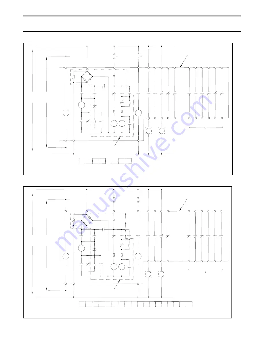
Fig. 30 125 VDC Control Circuit Schematic for MU Type Circuit Breaker
Fig. 31 125 VDC Control Circuit Schematic for ML Type Circuit Breaker
a3
a2
a1
b3
b2
b1
a6
b5
a4
a5
b6
b4
TC
UV
C4
K
15 14
13 12
11
16
15
14
13
12
11
C04
N2
25 24
23 22
21
26
24
25
22
23
21
C04
C4
N2
K
Terminal Layout
(As Viewed From Front of Circuit Breaker)
OFF
SUPPLY
+
-
RL
GL
120 VAC
SUPPLY
Optional Auxiliary Contacts
(Connect Wires Directly To
Auxiliary Switch Terminals)
Circuit Breaker Components
Shown Inside Box
SP
REC
M
LS2
LS3 LS3
X-b
R1
X-a
X-a
X-a
H
ON
PR3
D
R2
Y-b
X
Y
R3
Y-a
Y-b
C
R4
LS1
NT3
H
PR3 NT3
Components Inside Dashed Box Located
On Control Circuit Board
125 VDC
a3
a2
a1
b2
b1
b6
a5
b4
b5
a6
a4
TC
UV
C4
K
A2 A1
B2 B1
16
15
14
13
12
11
C04
N2
A02 A01 B02 B01
26
24
25
22
23
21
C04
C4
N2
K
Terminal Layout
(As Viewed From Front of Circuit Breaker)
OFF
SUPPLY
+
-
RL
GL
120 VAC
SUPPLY
Optional Auxiliary Contacts
(Connect Wires Directly To
Auxiliary Switch Terminals)
Circuit Breaker Components
Shown Inside Box
SP
REC
M
LS2
LS3 LS3
X-b
R1
X-a
X-a
X-a
H
ON
PR3
D
R2
Y-b
X
Y
R3
Y-a
Y-b
C
R4
LS1
NT3
H
PR3 NT3
Components Inside Dashed Box Located
On Control Circuit Board
125 VDC
A1
A2
B1
B2
A01
A02
B01
B02


