I-4
Service Manual
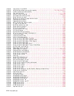
menus
accessing service menus
3-1
description
2-3
printing menu page
3-30
messages
check device connection messages
2-43
service error codes
2-8
user attendance messages
2-32
user line 2 link messages
2-43
user status displays
2-31
warning messages (user status displays)
2-31
Model Name
3-20
models
1-1
,
1-2
,
7-1
MPF arm assembly
4-60
MPF lower paper deflector
4-61
MPF solenoid assembly
4-62
multipurpose feeder
parts catalog
7-14
removal
4-15
N
narrow media sensor
See
fuser narrow media sensor
navigation buttons
2-2
number pad rubber dome sheet
7-3
numeric pad
2-3
O
operator panel
board
4-66
Button Test
3-7
buttons
2-106
,
4-67
,
7-3
description
2-2
display
2-107
LCD Brightness
3-29
LCD Contrast
3-29
Panel Test
3-7
parts catalog
7-2
service check
2-106
upper front cover
4-11
,
7-3
upper front cover bezel
4-14
options
descriptions
1-1
parts catalog
7-69
service checks
2-108
outer shield
parts catalog
7-32
removal
4-67
output bin sensor tests
5-bin mailbox
3-16
high-capacity output stacker
3-16
output expander
3-15
standard bin
3-15
output expander
output sensor test
3-15
parts catalog
7-48
,
7-49
service check
2-110
output expander control board
5-11
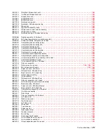
P
packaging
7-69
page count
Fuser Page Count
3-22
Page Count
3-20
permanent page count
3-20
Panel Test
3-7
paper and media specifications
1-8
paper bin full sensor flag
4-70
paper deflector assembly
inner
4-47
upper
4-79
paper feed jams
200 and 201 Paper Jam Remove Cartridge
3-37
202 Paper Jam Open Rear Door
3-39
23
x
and 24
x
jams
3-36
23
x
Paper Jam Open Duplex Rear Door
3-40
250 Paper Jam Check MP Feeder
3-34
260 Paper Jam Check Env Feeder
3-35
270 and 280 Paper Jams
3-41
27
x
Paper Jam Check Bin
x
3-41
28
x
Paper Jam Check Finisher
3-42
access doors and trays
3-33
clearing
3-33
paper jam error codes
2-44
paper size sensing board
2-113
,
4-71
paper support removal
4-5
parallel wrap tests
3-8
part number index
2-9
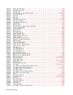
parts catalog
250-sheet paper drawer, option
7-42
250-sheet paper tray, option
7-43
500-sheet paper drawer, option
7-44
500-sheet paper tray, option
7-45
5-bin mailbox
7-54
,
7-56
cabling
7-34
,
7-35
,
7-36
,
7-38
,
7-40
covers
7-2
drives—main drive and developer drive
7-22
duplex option
7-46
electronics
card assemblies
7-30
power supplies
7-28
shields
7-32
envelope feeder
7-47
frame
7-4
,
7-6
,
7-8
high-capacity feeder
7-58
,
7-60
,
7-62
,
7-63
high-capacity output expander
7-50
,
7-51
hot roll fuser
7-24
integrated paper tray—250-sheet
7-18
integrated paper tray—500-sheet
7-20
kiosk, vertical and horizontal paper adapters
7-64
optional 250-sheet paper drawer
7-42
optional 250-sheet paper tray
7-43
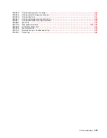
options
7-69
output expander
7-48
,
7-49
Summary of Contents for e-STUDIO500P
Page 1: ...PRINTER P N 12G9609 e STUDIO500P ...
Page 10: ...x Service Manual ...
Page 15: ...Laser notices xv Japanese Laser Notice ...
Page 16: ...xvi Service Manual Korean Laser Notice ...
Page 43: ...Diagnostic information 2 7 ...
Page 159: ...Diagnostic information 2 123 ...
Page 160: ...2 124 Service Manual ...
Page 161: ...Diagnostic information 2 125 ...
Page 181: ...Diagnostic aids 3 17 ...
Page 297: ...5 12 Service Manual ...
Page 298: ...Connector locations and connections 5 13 ...
Page 299: ...5 14 Service Manual ...
Page 301: ...6 2 Service Manual ...
Page 303: ...7 2 Service Manual Assembly 1 Covers ...
Page 305: ...7 4 Service Manual Assembly 2 Frame 1 ...
Page 307: ...7 6 Service Manual Assembly 3 Frame 2 ...
Page 309: ...7 8 Service Manual Assembly 4 Frame 3 ...
Page 311: ...7 10 Service Manual Assembly 5 Printhead ...
Page 313: ...7 12 Service Manual Assembly 6 Paper feed autocompensator ...
Page 315: ...7 14 Service Manual 4061 xx0 Assembly 7 Paper feed multipurpose feeder ...
Page 317: ...7 16 Service Manual Assembly 8 Paper feed alignment ...
Page 319: ...Page 7 19 has been removed from this document intentionally 7 18 Service Manual ...
Page 320: ...7 20 Service Manual Assembly 10 Integrated 500 sheet paper tray ...
Page 322: ...7 22 Service Manual Assembly 11 Drives Main drive and developer drive ...
Page 324: ...7 24 Service Manual Assembly 12 Hot roll fuser ...
Page 326: ...7 26 Service Manual Assembly 13 Transfer charging ...
Page 328: ...7 28 Service Manual Assembly 14 Electronics power supplies ...
Page 330: ...7 30 Service Manual Note ...
Page 332: ...7 32 Service Manual Assembly 16 Electronics shields ...
Page 336: ...7 36 Service Manual Assembly 19 Cabling diagrams 3 ...
Page 338: ...7 38 Service Manual Assembly 20 Cabling diagrams 4 ...
Page 340: ...7 40 Service Manual Assembly 21 Cabling diagrams 5 ...
Page 342: ...7 42 S ervice Manual THE FOLLOWING PAGE 7 43 HAS BEEN OMITTED FROM THIS MANUAL INTENTIONALLY ...
Page 347: ...7 48 S ervice Manual Pages 7 49 through 7 57 of this manual have been omitted intentionally ...
Page 348: ...7 58 Service Manual Assembly 35 High capacity feeder 1 ...
Page 350: ...7 60 Service Manual Assembly 36 High capacity feeder 2 ...
Page 354: ...7 64 S ervice Manual Pages 7 65 thru 7 70 ofthis manual were omitted intentionally ...
Page 362: ...I 8 Service Manual ...
Page 370: ...I 16 Service Manual ...


