e-STUDIO2020C/2330C/2820C/2830C/3520C/3530C/4520C
© 2008 - 2011 TOSHIBA TEC CORPORATION All rights reserved
ERROR CODE AND TROUBLESHOOTING
6 - 66
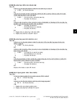
[C962] LGC board ID abnormality
(1)
Check if the connector CN344 on the LGC board is completely inserted or not disconnected.
(2)
Check if the connector CN423 on the IMG board and the connector CN354 on the LGC board
are completely inserted.
(3)
Check if the connector pin between the IMG board (connector CN423) and the LGC board
(connector CN354) is disconnected.
(4)
Check if the connector CN425 on the IMG board is completely inserted or not disconnected.
(5)
Check if the conductor patterns on the IMG board and the LGC board are short circuited or open
circuited.
(6)
Replace the LGC board if no problem is found in steps from (1) to (5) above.
(7)
If the problem is not corrected with the replacement of the LGC board, reinstall the removed LGC
board and replace the IMG board.
(8)
If the problem is still not corrected with the replacement of the IMG board, reinstall it and ask a
specialist to repair it. (Abnormal ID)
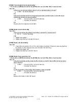
[C9E0] Connection error between the SLG board and the SYS board
(1)
Check if the connector CN12 on the SLG board is completely inserted or not disconnected.
(2)
Check if the connector CN421 on the IMG board is completely inserted or not disconnected.
(3)
Check if the connector pin between the SLG board (connector CN12) and the IMG board
(connector CN421) is disconnected, or the harness connecting these boards is short circuited or
open circuited.
(4)
Check if the connector CN422 on the IMG board and the connector CN135 on the SYS board are
completely inserted.
(5)
Check if the connector pin between the IMG board (connector CN422) and the SYS board
(connector CN135) is disconnected.
(6)
Check if the conductor patterns on the SLG board, IMG board and SYS board are short circuited
or open circuited.
(7)
Replace the SLG board if no problem is found in steps from (1) to (6) above.
(8)
If the problem is not corrected with the replacement of the SLG board, reinstall the removed SLG
board and replace the IMG board.
(9)
If the problem is still not corrected with the replacement of the IMG board, reinstall the removed
IMG board and replace the SYS board.
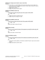
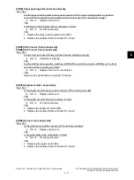
[F090] SRAM abnormality on the SYS board
(1)
Turn the power OFF and start up the Setting Mode (08).
(2)
When “SRAM ERROR DOES IT INITIALIZE” is displayed on the LCD, check the destination and
then press the [START] button. If the destination is not correct, key in the correct one and then
press the [START] button. (SRAM is initialized.)
(3)
After the confirmation message is displayed, press the [INTERRUPT] button.
(4)
Perform the panel calibration (08-692).
(5)
Enter the serial number (08-995). Match it with the serial number on the label attached to the rear
cover of the equipment.
(6)
Initialize the NIC information (08-693).
(7)
Turn the power OFF and then start up with the Adjustment mode (05).
(8)
Perform “Data transfer of characteristic value of scanner” (05-364).
(9)
Perform “Automatic gamma adjustment” <PPC> (05-1642). (using [4][FAX] test pattern)
(10) Perform “Automatic gamma adjustment” <PRT> (05-1008). (using [70][FAX] test pattern)
(11) Turn the power OFF and then back ON. If the error is not recovered, replace the SRAM on the
SYS board.

