e-STUDIO2020C/2330C/2820C/2830C/3520C/3530C/4520C
© 2008 - 2011 TOSHIBA TEC CORPORATION All rights reserved
SELF-DIAGNOSTIC MODE
2 - 70
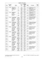
2.5.7
Scanner
Adjustment mode (05)
Code
Classific
ation
Items
Functi
on
Default
<Accept
able
value>
RAM
Contents
Proce
dure
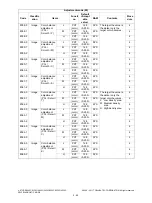
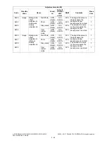
305
Scanner
Image location adjustment
of secondary scanning
direction
(scanner section)
ALL
124
<68-188>
SYS
When the value
increases by “1”, the
image shifts by approx.
0.08333 mm toward the
trailing edge of the
paper.
1
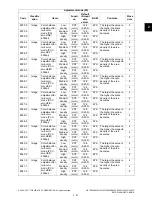
306
Scanner
Image location adjustment
of
primary
scanning
direction
(scanner section)
ALL
113
<0-255>
SYS
When the value
increases by “1”, the
image shifts by approx.
0.0423 mm toward the
front side of the paper.
1
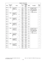
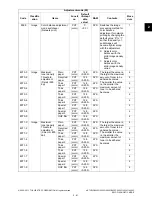
308
Scanner
Distortion mode
ALL
-
-
Moves carriages to the
adjusting position.
(Ch.3.1.9)
6
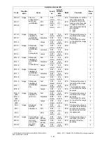
340
Scanner
Reproduction ratio
adjustment of secondary
scanning direction
(scanner section)
ALL
128
<0-255>
SYS
When the value
increases by “1”, the
reproduction ratio in the
secondary scanning
direction (vertical to
paper feeding direction)
increases by approx.
0.017%.
1
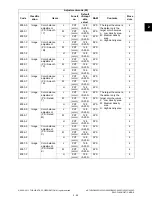
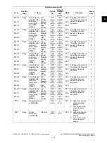
357
RADF
Fine adjustment of RADF
transport speed
ALL
50
<0-100>
SYS
When the value
increases by “1”, the
reproduction ratio of the
secondary scanning
direction on original (fed
from the RADF)
increases by approx.
0.1%.
1
358
RADF
RADF sideways deviation
adjustment
ALL
128
<0-255>
SYS
When the value
increases by “1”, the
image of original fed
from the RADF shifts
toward the rear side of
paper by approx.
0.0423 mm.
1
363
Scanner
Data transfer of
characteristic value of
scanner / SYS board
→
SLG board
SCN
-
SYS
Transfers the
characteristic values of
the scanner (shading
correction factor / RGB
color correction /
reproduction ratio color
aberration correction /
shading position
correction factor /
reproduction ratio
correction value in
primary scanning
direction) from the
SRAM of the SYS
board to the SRAM of
the SLG board.
6

