background image

4

© 2011 - 2015 TOSHIBA TEC CORPORATION All rights reserved

e-STUDIO5540C/6540C/6550C/5560C/6560C/6570C

DISASSEMBLY and REPLACEMENT

4 - 1

4. DISASSEMBLY and REPLACEMENT

4.1

Disassembly and Replacement of Covers

4.1.1

Front lower cover

4.1.2

Front cover

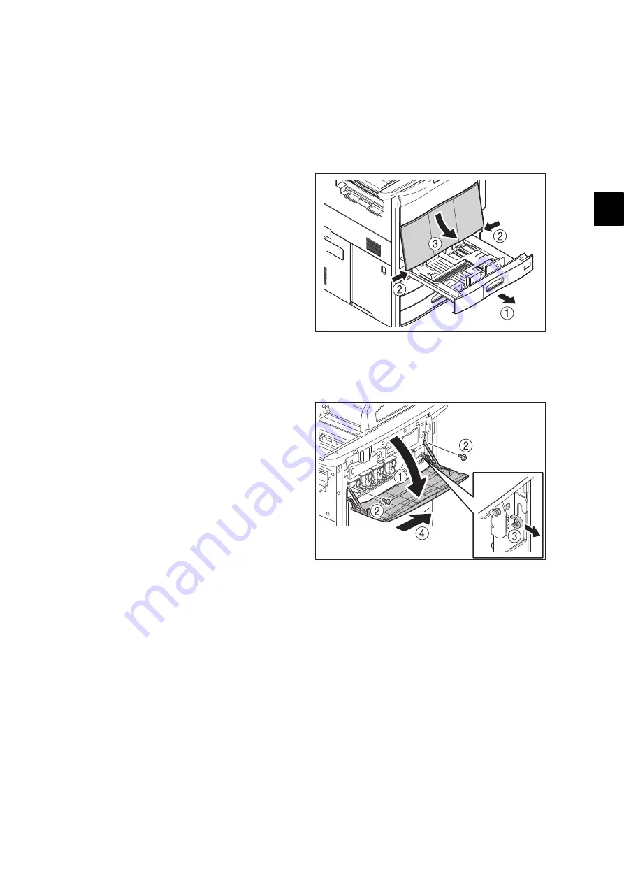
(1) Pull out the 1st drawer.
(2) Loosen 2 screws.
(3) Take off the front lower cover.

Fig. 4-1

(1) Take off the front lower cover.

 P. 4-1"4.1.1 Front lower cover"

(2) Open the front cover.
(3) Remove 2 screws and take off the cover 

support.

(4) Remove 1 clip.
(5) Lift up the supporting point of the left side 

hinge and move the front cover to the right 
side to take it off.

Fig. 4-2

Summary of Contents for E-Studio 5540c

Page 1: ...AL MULTIFUNCTIONAL DIGITAL COLOR SYSTEMS e STUDIO5540C 6540C 6550C e STUDIO5560C 6560C 6570C Model FC 5540C 6540C 6550C 5560C 6560C 6570C Publish Date April 2011 File No SME100009K0 R100321I6506 TTEC Ver11F_2015 05 ...

Page 2: ...roducts are trademarks of Microsoft Corporation in the US and other countries Apple AppleTalk Macintosh and Mac are trademarks of Apple Inc in the U S and other countries PostScript is a trademark of Adobe Systems Incorporated NOVELL NetWare and NDS are trademarks or registered trademarks of Novell Inc FLOIL is a registered trademark of Kanto Kasei Ltd CORPORATION Mylar is a registered trademark o...

Page 3: ...hall be easily accessible Be sure to fix and plug in the power cable securely after the installation so that no one trips over it If the unpacking place and where the equipment is to be installed differ perform image quality adjustment automatic gamma adjustment according to the temperature and humidity of the place of installation and the paper to be used When the equipment is used after the opti...

Page 4: ...g your eyes to laser beam Use designated jigs and tools Use recommended measuring instruments or equivalents Return the equipment to the original state and check the operation when the service is finished Be very careful to treat the touch panel gently and never hit it Breaking the surface could cause malfunctions Do not leave plastic bags where children can get at them This may cause an accident ...

Page 5: ...their surface and if they are properly stuck to the equipment 1 Identification label 2 Explanatory label 3 Certification label 4 Warning for grounding wire 5 Warning for high temperature area Duplexing unit Fuser unit 6 Warning for high temperature area Fuser unit 7 Warning for high temperature area Bridge unit 1 2 4 5 6 7 3 ...

Page 6: ...before performing maintenance and inspection otherwise troubles such as a communication error may occur 8 Handling the heat pipe roller When discarding the heat pipe roller do so after opening a hole from the axial edge of the D cut side Never attempt to incinerate it Caution Dispose of used batteries and IC RAMs including lithium batteries according to this manual Attention Se débarrasser de batt...

Page 7: ... at unpacking to reuse it in steps 2 and 3 above Use a service jig PLATE TONER SEAL 4P 6LH035950 4 pieces in 1 set as sealing material to be used in step 4 above Do not install the accessories shown below when unpacking the equipment Item Content 1 Gasket in Reversing Automatic Document Feeder RADF Check that gaskets are not installed in the RADF If they are installed remove them 2 Scanning sectio...

Page 8: ...ice Do not install the gaskets in the equipment before transporting it because if it is transported with the gaskets installed the screws fixing the scanner may contact with the gaskets and thus damage them 2 2 Fixing the scanning section 1 Move carriage 1 until it touches the left side of the frame Then move it back to the right for 3 mm Notes Rotate a drive pulley by hand to move carriage 1 P 4 ...

Page 9: ... be performed when the equipment is unpacked but must be when it is reinstalled at a user s office The installation of grounding screws in the RADF which is described in the Unpacking Instructions must not be performed when the equipment is unpacked but must be when it is reinstalled at a user s office Install them after you have removed the screws reinstalled in step 2 ...

Page 10: ... sheet removed at unpacking Store the drum protection sheet in a place without high temperature and humidity direct sunlight or dust Do not scratch or bend the drum protection sheet Avoid adhesion of dust dirt or foreign matter especially things that may damage the surface of the drums or the transfer belt e g hard matter or matter that is highly adhesive organic or chemical matter grease to the d...

Page 11: ...ing transported Pack them separately from the equipment 2 Install PLATE TONER SEAL 4P 6LH035950 in the toner supply opening of each toner cartridge Then close the front cover Notes Pay attention to prevent dust from entering into the toner supply openings When installing PLATE TONER SEAL 4P 6LH035950 be careful not to scratch or remove the sponge that is already attached to the toner supply openin...

Page 12: ...nstallieren diese muss leicht zu erreichen sein Nach der Installation muss das Netzkabel richtig hineingesteckt und befestigt werden damit niemand darüber stolpern kann Falls der Auspackungsstandort und der Installationsstandort des Geräts verschieden sind die Bildqualitätsjustierung automatische Gammajustierung je nach der Temperatur und Luftfeuchtigkeit des Installationsstandorts und der Papiers...

Page 13: ...wenden Nach Abschluss der Wartungsarbeiten das Gerät in den ursprünglichen Zustand zurück versetzen und den einwandfreien Betrieb überprüfen Das berührungsempfindliche Bedienungsfeld stets vorsichtig handhaben und keinen Stößen aussetzen Wenn die Oberfläche beschädigt wird kann dies zu Funktionsstörungen führen Bewahren Sie Kunststofftüten kindersicher auf Es besteht Erstickungsgefahr wenn sich Ki...

Page 14: ...ereiche mit höhen Temperaturen Duplexeinheit Fixiereinheit 6 Warnung für Bereiche mit höhen Temperaturen Fixiereinheit 7 Warnung für Bereiche mit höhen Temperaturen Brückeneinheit 6 Entsorgung des Geräts der Verbrauchs und Verpackungsmaterialien alter Akkus und IC RAMs In Bezug auf die Entsorgung und Wiederverwertung des Geräts der Verbrauchs und Verpackungsmaterialien alter Akkus und IC RAMs eins...

Page 15: ...lithium batteries according to this manual Attention Se débarrasser de batteries et IC RAMs usés y compris les batteries en lithium selon ce manuel Vorsicht Entsorgung der gebrauchten Batterien und IC RAMs inclusive der Lithium Batterie nach diesem Handbuch ...

Page 16: ...position durch Laserstrahlung kommen Die Lasereinheit ist vollständig mit einer Schutzabdeckung versiegelt Solange ausschließlich die Arbeitsschritte der vorgeschriebenen Anleitungen durchgeführt werden tritt der Laserstrahl nicht aus und es besteht keine Gefahr der Laserstrahlung ausgesetzt zu werden Das folgende Laser Warnetikett ist an der Abdeckung vorne rechts angebracht Warnhinweise Setzen S...

Page 17: ... 28 3 3 2 Fans 3 30 3 3 3 Sensors 3 31 3 3 4 Switches 3 36 3 3 5 Electromagnetic spring clutches 3 36 3 3 6 Solenoids 3 37 3 3 7 PC boards 3 38 3 3 8 Lamps coils and heaters 3 39 3 3 9 Thermistors thermopiles and thermostats 3 39 3 3 10 Transformer 3 40 3 3 11 Others 3 40 3 4 Copy Process 3 41 3 5 Comparison with e STUDIO5520C 6520C 6530C 3 42 3 6 Comparison with e STUDIO5540C 6540C 6550C 3 44 3 7...

Page 18: ...s 3 110 3 17 Reversing Automatic Document Feeder RADF 3 113 3 17 1 General Description 3 113 3 17 2 Functions 3 114 3 17 3 Description of Operation 3 115 3 18 Power Supply Unit 3 119 3 18 1 General Description 3 119 3 18 2 Composition 3 119 3 18 3 Operation of DC Output Circuits 3 120 3 18 4 Output Channel 3 122 3 18 5 Fuse 3 124 4 DISASSEMBLY and REPLACEMENT 4 1 4 1 Disassembly and Replacement of...

Page 19: ...sition sensor S6 4 34 4 3 17 Platen sensor S7 4 34 4 3 18 SLG board SLG 4 34 4 4 Laser Optical Unit 4 35 4 4 1 Laser optical unit 4 35 4 4 2 Laser optical unit cooling fan front F22 4 38 4 4 3 Laser optical unit cooling fan rear F23 4 40 4 4 4 Shutter 4 41 4 4 5 Shutter motor 4 41 4 4 6 Shutter sensor home position 4 42 4 4 7 Shutter sensor end position 4 43 4 4 8 Disassembly and replacement of th...

Page 20: ...O5560C 6560C 6570C 4 73 4 5 44 4th drawer transport clutch CLT6 4th drawer feed clutch CLT7 e STUDIO5540C 6540C 6550C 4 74 4 5 45 4th drawer transport clutch CLT6 4th drawer feed clutch CLT7 e STUDIO5560C 6560C 6570C 4 74 4 5 46 Tray up motor 1 M44 4 75 4 5 47 Tray up motor 2 M45 4 77 4 5 48 Transfer belt paper clinging detection sensor S47 4 78 4 5 49 Tandem LCF tray up motor M46 4 79 4 5 50 Tand...

Page 21: ... 4 120 4 6 34 Developer unit motor K YMC M29 M31 4 121 4 6 35 Developer unit mixer motor K YMC M30 M32 4 121 4 6 36 Developer drive unit 4 121 4 6 37 Waste toner box 4 122 4 6 38 Waste toner amount detection sensor S13 4 123 4 6 39 Waste toner box full detection sensor S14 4 124 4 6 40 Waste toner box detection sensor S16 4 125 4 6 41 Ozone filter 1 4 125 4 6 42 Ozone filter 2 4 126 4 6 43 Toner f...

Page 22: ... roller cover 4 173 4 9 3 Transport guide 1 4 174 4 9 4 Transport guide 2 4 174 4 9 5 Entrance guide cover 4 175 4 9 6 Separation finger 4 175 4 9 7 Separation plate 4 176 4 9 8 Pressure roller Pressure roller heater lamp LAMP 4 178 4 9 9 Fuser belt Fuser roller Fuser belt guide Heat pipe roller 4 182 4 9 10 Fuser belt rotation detection sensor S49 4 188 4 9 11 Fuser belt thermostat THMO4 4 189 4 ...

Page 23: ... jam detection sensor S58 4 232 4 10 29 Exit paper cooling fan front F5 4 233 4 10 30 Bridge unit cooling fan front F6 4 235 4 10 31 Bridge unit cooling fan rear F7 4 236 4 10 32 Front cover opening closing detection switch SW9 Bridge unit connecting detection switch SW8 4 237 4 10 33 Duplexing bridge unit 4 238 4 10 34 Duplexing unit opening closing detection sensor S64 4 238 4 10 35 Reverse path...

Page 24: ...closing switch SWR1 4 289 4 11 35 RADF opening closing switch SWR2 4 289 4 11 36 RADF opening closing sensor SR15 4 291 4 11 37 Original empty sensor SR3 4 291 4 11 38 Original jam access cover opening closing sensor SR13 4 292 4 11 39 Feeder lower guide unit 4 292 4 11 40 Original width detection sensor 3 SR8 4 293 4 11 41 Original width detection sensor 2 SR7 4 293 4 11 42 Original width detecti...

Page 25: ...16 Batch Setting for Self Diagnostic Codes 5 61 5 16 1 General description 5 61 5 16 2 Applicable codes 5 61 5 16 3 Setting files 5 61 5 16 4 Result files 5 62 5 16 5 Operation procedure 5 63 6 SETTING ADJUSTMENT 6 1 6 1 Image Related Adjustment 6 1 6 1 1 Adjustment Order 6 1 6 1 2 Adjustment of the Auto Toner Sensor 6 2 6 1 3 Performing Image Quality Control 6 4 6 1 4 Adjustment of Color Registra...

Page 26: ...ment 6 66 6 3 17 Color black judgment setting for twin color printing images 6 66 6 3 18 Background adjustment 6 67 6 3 19 Density adjustment of graphic lines 1200 dpi 6 68 6 3 20 Beam level conversion setting 6 69 6 4 Image Quality Adjustment Scanning Function 6 70 6 4 1 Gamma balance adjustment 6 70 6 4 2 Density adjustment 6 71 6 4 3 Background adjustment Color Mode 6 72 6 4 4 Judgment threshol...

Page 27: ...INTENANCE PM 7 1 7 1 General Description 7 1 7 2 PM Display 7 1 7 2 1 General Description 7 1 7 2 2 PM Display Conditions 7 1 7 2 3 PM Display Contents 7 2 7 2 4 Counter Clearing 7 3 7 3 General Descriptions for PM Procedure 7 4 7 4 PM Support Mode 7 5 7 4 1 General Description 7 5 7 4 2 Operational flow 7 5 7 4 3 Operational screen 7 6 7 4 4 Access tree 7 11 7 5 General Description 7 13 7 6 Preve...

Page 28: ...ternal application 8 34 8 2 6 MFP access error 8 36 8 2 7 Maintenance error 8 36 8 2 8 Network error 8 37 8 2 9 Error history 8 40 8 3 Diagnosis and Prescription for Each Error Code 8 42 8 3 1 Check item 8 42 8 3 2 Paper transport jam paper exit section 8 42 8 3 3 Paper misfeeding 8 45 8 3 4 Paper transport jam 8 50 8 3 5 Other paper jam 8 66 8 3 6 Cover open jam 8 75 8 3 7 RADF jam 8 78 8 3 8 Jam...

Page 29: ...tput time for black in the MFP with 55 cpm exceeds approx 5 3 sec 8 292 8 4 16 Error code M00 is displayed while updating firmware 8 293 8 5 Troubleshooting for the Image 8 294 8 5 1 Color deviation 8 294 8 5 2 Uneven pitch and jitter image 8 296 8 5 3 Black spot color point 8 298 8 5 4 Poor image density color reproduction and gray balance 8 299 8 5 5 Background fogging 8 301 8 5 6 Moire lack of ...

Page 30: ...rd 9 34 9 2 6 Precautions and Procedures when replacing SRAM board for SYS board 9 35 9 2 7 Precautions and Procedures when replacing SRAM board for LGC board 9 42 9 2 8 Firmware confirmation after the PC board HDD replacement 9 47 9 2 9 License re registration using the one time dongle 9 48 9 3 Precautions for Installation of GP 1070 and Disposal of HDD Board 9 50 9 3 1 Precautions for Installati...

Page 31: ...HDD when data encryption function is enabled 12 9 12 3 High Security Mode 12 10 12 3 1 General description 12 10 12 3 2 Prior confirmation 12 10 12 3 3 Procedure for entering the High Security Mode 12 10 12 3 4 Precautions 12 11 13 EXTERNAL COUNTERS 13 1 13 1 Outline 13 1 13 2 Signal 13 1 13 2 1 Pin Layout 13 1 13 2 2 Details of the signals 13 3 13 3 Notices 13 5 13 3 1 Setting code 13 5 13 3 2 Se...

Page 32: ...CORPORATION All rights reserved CONTENTS 16 e STUDIO5560C 6560C 6570C Adjustment Mode 05 Codes 1657 Setting Mode 08 Codes 1797 APPENDIX 2016 Preventive Maintenance Checklist e STUDIO5540C 6540C 6550C 2016 Preventive Maintenance Checklist e STUDIO5560C 6560C 6570C 2017 ...

Page 33: ...improves the gloss of the toner The life of the developer material is lengthened and the service cost for the replacement is reduced due to the new self refreshing development system Replacing toner cartridges and supplying paper to the tandem LCF can be performed while the equipment is being operated The SVGA large color LCD 10 4 inches is adopted for the touch panel A maximum of 256 g m2 94 5 lb...

Page 34: ...e STUDIO5540C 6540C 6550C 5560C 6560C 6570C 2011 2015 TOSHIBA TEC CORPORATION All rights reserved FEATURE 1 2 ...

Page 35: ... 2500 sheets 80 g m2 23 lb Bond Tandem LCF Stack height 270 mm equivalent to 2360 sheets 80 g m2 23 lb Bond Paper size Drawers A3 A4 A4 R A5 R B4 B5 B5 R FOLIO 8K 16K 16K R A3Wide 305 x 457 mm SRA3 320 x 450 mm 320 x 460 mm LD LG LT LT R ST R COMPUTER 13 LG 8 5 x 8 5 Full Bleed 12 x 18 Bypass feeding A3 A4 A4 R A5 R B4 B5 B5 R FOLIO 8K 16K 16K R A3Wide 305 x 457 mm SRA3 320 x 450 mm 320 x 460 mm 3...

Page 36: ...oner density adjustment Magnetic auto toner system Pixel counter control system Total counter Electronical counter Memory RAM Main memory 1 GB Page Memory 1 GB HDD 80GB For hard drives GB means 1 billion bytes e STUDIO5540C 6540C 6550C 320GB For hard drives GB means 1 billion bytes e STUDIO5560C 6560C 6570C Account Codes 10 000 codes Department Codes 1 000 codes Warm up time Approx 180 sec Stand a...

Page 37: ...ge is 10 Rated frequency 50 60 Hz 50 60 Hz 50 60 Hz Rated current e STUDIO5540C 16 A 10 A 13 A e STUDIO6540C 18 5 A e STUDIO6550C e STUDIO5560C 16 A 10 A 10 A e STUDIO6560C 18 5 A e STUDIO6570C Power consumption e STUDIO5540C 2 0 kW or less 2 4 kW or less 3 2 kW or less e STUDIO6540C 2 2 kW or less e STUDIO6550C e STUDIO5560C 2 0 kW or less 2 4 kW or less 2 4 kW or less e STUDIO6560C 2 2 kW or les...

Page 38: ...l paper weight Single sided copy 35 209 g m2 9 3 lb Bond 110 lb Index Double sided copy 50 157 g m2 13 3 lb Bond 40 lb Bond You may not obtain enough image quality when an original with a paper weight of more than 157 g m2 41 8 lb is used Original capacity Max 100 sheets 80 g m2 Stack height 16 mm Eliminated portion Black copy Leading edges 4 2 2 8 1 2 mm Trailing edges 3 0 2 0 mm Side edges 2 0 2...

Page 39: ...Tandem LCF Size specified Size not specified A4 LT 55 55 46 46 17 17 55 55 55 55 B5 A5 R ST R A4 R B5 R LT R 38 38 35 35 17 17 B4 LG FOLIO COMPUTER 29 29 27 27 17 17 A3 LD 27 27 24 24 17 17 305 x 457mm SRA3 320 x 450mm 25 25 20 20 Paper supply Paper size Drawer Bypass feed Option LCF Tandem LCF Size specified Size not specified A4 LT 65 65 48 48 18 18 65 65 65 65 B5 A5 R ST R A4 R B5 R LT R 46 46 ...

Page 40: ...C 6560C 6570C Paper supply Paper size Drawer Bypass feed Option LCF Tandem LCF Size specified Size not specified A4 LT 32 32 26 26 8 8 32 32 32 32 B5 A5 R ST R A4 R B5 R LT R 23 23 20 20 8 8 B4 LG FOLIO COMPUTER 15 5 15 5 13 13 8 8 A3 LD 13 5 13 5 11 11 8 8 305 x 457mm SRA3 320 x 450mm 12 12 9 9 Paper supply Paper size Drawer Bypass feed Option LCF Tandem LCF Size specified Size not specified A4 L...

Page 41: ... Drawer Bypass feed Option LCF Tandem LCF Size specified Size not specified A4 LT 6 6 1 5 1 5 B5 A5 R ST R A4 R B5 R LT R 4 5 4 5 1 5 1 5 B4 LG FOLIO COMPUTER 3 3 1 5 1 5 A3 LD 2 5 2 5 1 5 1 5 305 x 457mm SRA3 320 x 450mm 2 2 1 5 1 5 Paper supply Paper size Drawer Bypass feed Option LCF Tandem LCF Size specified Size not specified A4 LT 17 17 5 5 B5 A5 R ST R A4 R B5 R LT R 13 13 5 5 B4 LG FOLIO C...

Page 42: ...the color mode Copy mode Sec e STUDIO5540C e STUDIO5560C e STUDIO6540C e STUDIO6560C e STUDIO6550C e STUDIO6570C Single sided originals Single sided copies 1 set 17 49 18 69 16 84 17 22 14 05 17 22 3 sets 36 10 40 28 35 20 35 39 30 01 35 39 5 sets 60 74 61 79 53 52 53 67 45 84 53 67 Single sided originals Double sided copies 1 set 22 00 23 18 20 51 22 01 22 15 22 01 3 sets 43 62 44 76 38 85 40 27 ...

Page 43: ... 1200 x 1200 dpi 2bit PS only Eliminated portion Black print Color print Leading edges 4 2 2 8 1 2 mm Trailing edges 4 2 1 2 2 8 mm Side edges 4 2 2 0 mm Interface Standard USB 2 0 High Speed Ethernet 10BASE T 100BASE TX 1000BASE T Optional WLAN IEEE 802 11b g Scanning speed Black 62 sheets min Text Photo 600 x 600 dpi 62 sheets min Gray scale 600 x 600 dpi Color 53 sheets min Text Photo Resolutio...

Page 44: ...p Max 200 stations Transmission Features Broadcast transmission Max 400 destinations job Fax number and E mail address are available to registered in same job Message size limitation Max 100M Byte Message division Page by page Format of receive attachment TIFF FX Profile S F J Compatibility Super G3 G3 ITU T 30 Internet Fax Simple mode ITU T 37 TX Resolution PSTN Standard 200 x 100 dpi Fine 200 x ...

Page 45: ... feeding tray spacer 1 pc Power cable MJC MJD 1 pc e STUDIO5540C e STUDIO5560C 6560C 6570C 2 pcs e STUDIO6540C 6550C ASU ASD ARD AUC AUD CND 1 pc Warranty sheet 1 pc for NAC NAD Setup report 1 set for NAC NAD MJC MJD CND PM sticker 1 pc for MJC MJD Cleaning cloth 1 pc Cloth case 1 pc Rubber plug 5 pcs Gasket 2 pcs Blind seal 2 pcs DVD 1 pc Client Utilities User Documentation DVD Developer material...

Page 46: ... 1270 NA AU AS EU C 2nd Line for FAX Unit GD 1260 NA AU EU C Hole Punch Unit MJ 6102 N E F S Damp Heater Kit MF 5520E U Saddle Stitch Finisher MJ 1104 Staple Cartridge STAPLE 3100 Staple Cartridge STAPLE 2400 Finisher MJ 1103 Exit tray KA 6550 ET C Finisher Guide Rail KN 1103 e BRIDGE ID Gate Felica KP 2004 e BRIDGE ID Gate MIFARE KP 2005 Large Capacity Feeder LCF MP 2501A L Harness kit for coin c...

Page 47: ...260 NA AU EU C Hole Punch Unit MJ 6102 N E F S Damp Heater Kit MF 5520E U Saddle Stitch Finisher MJ 1104 Staple Cartridge STAPLE 3100 Staple Cartridge STAPLE 2400 Finisher MJ 1103 Exit tray KA 6550 ET C Finisher Guide Rail KN 1103 e BRIDGE ID Gate HID KP 2004 e BRIDGE ID Gate MIFARE KP 2005 Large Capacity Feeder LCF MP 2501A L Harness kit for coin controller GQ 1200 Data Overwrite Enabler GP 1070 ...

Page 48: ...e PS ZTFC75EY for Europe PS ZTFC65DY for Australia and Asia PS ZTFC75DY for Australia PS ZTFC65CY for China PS ZTFC65AY for Argentina PS ZTFC75AY for Argentina PS ZTFC75PY for Others Toner cartridge M PS ZTFC65M for North America Central and South America PS ZTFC75UM for North America PS ZTFC65EM for Europe PS ZTFC75EM for Europe PS ZTFC65DM for Australia and Asia PS ZTFC75DM for Australia PS ZTFC...

Page 49: ...A TEC CORPORATION All rights reserved e STUDIO5540C 6540C 6550C 5560C 6560C 6570C OUTLINE OF THE MACHINE 3 1 3 OUTLINE OF THE MACHINE 3 1 Sectional View 3 1 1 Front side Fig 3 1 1 2 3 4 5 6 7 8 9 10 11 12 13 14 15 16 17 ...

Page 50: ...N OFF button 10 Bypass feed unit 2 Control Panel 11 Paper Feeding System 3 Exit tray 12 Exit Reverse Section 4 Reversing Automatic Document Feeder RADF 13 Toner cartridge 5 Scanner 14 Transfer belt unit 6 Main power switch 15 Process Unit Related Section 7 Fuser Unit 16 Laser Optical Unit 8 2nd transfer unit 17 Waste toner box 9 Duplex Section ...

Page 51: ...IO5540C 6540C 6550C 5560C 6560C 6570C OUTLINE OF THE MACHINE 3 3 3 1 2 Rear side Fig 3 2 MR4 M1 M7 M8 MR3 MR1 MR2 M2 M15 M16 M17 M18 M29 M30 M31 M32 M33 M38 M13 M28 M27 M34 M35 M36 M37 M48 M39 M12 M43 M44 M45 M46 M47 M40 M42 M41 M11 M10 M5 M3 M4 M22 M21 M20 M19 M6 ...

Page 52: ...6570C 2011 2015 TOSHIBA TEC CORPORATION All rights reserved OUTLINE OF THE MACHINE 3 4 3 2 Electric Parts Layout A Reversing Automatic Document Feeder RADF Fig 3 3 SR1 SR2 SWR2 SR3 SR13 SR15 SR5 SR14 SR10 SR9 SR4 SR11 SWR1 SR6 SR7 SR8 SR12 ...

Page 53: ...3 2011 2015 TOSHIBA TEC CORPORATION All rights reserved e STUDIO5540C 6540C 6550C 5560C 6560C 6570C OUTLINE OF THE MACHINE 3 5 Fig 3 4 SOLR3 SOLR1 MR3 RADF SOLR2 FR1 MR4 MR2 MR1 ...

Page 54: ...C 6550C 5560C 6560C 6570C 2011 2015 TOSHIBA TEC CORPORATION All rights reserved OUTLINE OF THE MACHINE 3 6 B Scanner unit Fig 3 5 CCD S4 S3 A4 series only S2 S1 SLG EXP F2 F26 F1 S5 LT series S5 A4 series M1 S7 S6 F3 INV ...

Page 55: ...IBA TEC CORPORATION All rights reserved e STUDIO5540C 6540C 6550C 5560C 6560C 6570C OUTLINE OF THE MACHINE 3 7 C Bridge unit Paper exit Fig 3 6 F6 SOL1 F5 S58 S56 SOL2 S61 S62 S63 S60 SW5 S55 S59 S57 M4 M3 M5 M2 DRV F7 ...

Page 56: ... 6540C 6550C 5560C 6560C 6570C 2011 2015 TOSHIBA TEC CORPORATION All rights reserved OUTLINE OF THE MACHINE 3 8 D Fuser related section Fig 3 7 S48 F15 CLT1 M6 S65 THM4 THMO4 THMP1 THM5 THMO3 THM3 THMO2 S49 F21 THM6 ...

Page 57: ...C CORPORATION All rights reserved e STUDIO5540C 6540C 6550C 5560C 6560C 6570C OUTLINE OF THE MACHINE 3 9 Fig 3 8 IH F8 F9 IH COIL LAMP Center heater lamp Side heater lamp Sub heater lamp for e STUDIO5540C 6540C 6550C MJC MJD ...

Page 58: ...e STUDIO5540C 6540C 6550C 5560C 6560C 6570C 2011 2015 TOSHIBA TEC CORPORATION All rights reserved OUTLINE OF THE MACHINE 3 10 E Developer unit Fig 3 9 M29 S44 M31 M32 S43 M30 M28 M27 ...

Page 59: ...3 2011 2015 TOSHIBA TEC CORPORATION All rights reserved e STUDIO5540C 6540C 6550C 5560C 6560C 6570C OUTLINE OF THE MACHINE 3 11 Fig 3 10 THM2 S34 S29 S33 S32 S31 S12 S30 THM1 S28 S27 S26 ...

Page 60: ...540C 6540C 6550C 5560C 6560C 6570C 2011 2015 TOSHIBA TEC CORPORATION All rights reserved OUTLINE OF THE MACHINE 3 12 Fig 3 11 M26 ERS Y SOL4 M22 M25 M24 ERS C ERS M M23 ERS K F20 F19 F18 F17 M20 M19 M21 V0S EPU ...

Page 61: ...3 2011 2015 TOSHIBA TEC CORPORATION All rights reserved e STUDIO5540C 6540C 6550C 5560C 6560C 6570C OUTLINE OF THE MACHINE 3 13 F Transfer belt unit Fig 3 12 M14 M13 S46 ...

Page 62: ... STUDIO5540C 6540C 6550C 5560C 6560C 6570C 2011 2015 TOSHIBA TEC CORPORATION All rights reserved OUTLINE OF THE MACHINE 3 14 G Transfer unit Fig 3 13 M39 M48 SOL3 S22 M10 M11 S21 S52 S50 S51 S47 S20 S23 ...

Page 63: ... 2015 TOSHIBA TEC CORPORATION All rights reserved e STUDIO5540C 6540C 6550C 5560C 6560C 6570C OUTLINE OF THE MACHINE 3 15 H Laser unit Fig 3 14 LDR K M34 LDR M LDR C LDR Y SNS F22 M36 S25 S24 M38 M35 M37 F23 ...

Page 64: ...40C 6550C 5560C 6560C 6570C 2011 2015 TOSHIBA TEC CORPORATION All rights reserved OUTLINE OF THE MACHINE 3 16 I Toner cartridge Waste toner box Fig 3 15 S8 S9 S10 S11 S14 S13 M33 S38 S42 S39 S40 S41 S16 M15 M16 M17 M18 ...

Page 65: ...2011 2015 TOSHIBA TEC CORPORATION All rights reserved e STUDIO5540C 6540C 6550C 5560C 6560C 6570C OUTLINE OF THE MACHINE 3 17 J Automatic duplexing unit Fig 3 16 M8 ADU M7 S66 F11 S64 S67 LED SW2 SW7 SW4 ...

Page 66: ...UDIO5540C 6540C 6550C 5560C 6560C 6570C 2011 2015 TOSHIBA TEC CORPORATION All rights reserved OUTLINE OF THE MACHINE 3 18 K Cover switches Cover sensor TRU waste toner box Fig 3 17 S17 SW9 SW3 SW8 S114 SW1 ...

Page 67: ...3 2011 2015 TOSHIBA TEC CORPORATION All rights reserved e STUDIO5540C 6540C 6550C 5560C 6560C 6570C OUTLINE OF THE MACHINE 3 19 L Bypass feed unit Fig 3 18 M12 S70 S72 SOL8 S71 S69 ...

Page 68: ... 5560C 6560C 6570C 2011 2015 TOSHIBA TEC CORPORATION All rights reserved OUTLINE OF THE MACHINE 3 20 M Paper feeding section Fig 3 19 M40 S74 M41 CLT4 CLT5 CLT6 CLT7 M42 M44 M45 S98 S90 S82 S104 S103 S96 S95 S88 S87 S80 S79 M43 ...

Page 69: ...15 TOSHIBA TEC CORPORATION All rights reserved e STUDIO5540C 6540C 6550C 5560C 6560C 6570C OUTLINE OF THE MACHINE 3 21 Fig 3 20 S97 S99 S100 S78 S77 S86 S85 S94 S93 S102 S101 S73 S75 S76 S81 S83 S84 S89 S91 S92 ...

Page 70: ...DIO5540C 6540C 6550C 5560C 6560C 6570C 2011 2015 TOSHIBA TEC CORPORATION All rights reserved OUTLINE OF THE MACHINE 3 22 N Tandem LCF Fig 3 21 S108 S107 SOL11 SOL9 M47 M46 S111 S109 S106 SOL10 S113 S110 S112 ...

Page 71: ... TOSHIBA TEC CORPORATION All rights reserved e STUDIO5540C 6540C 6550C 5560C 6560C 6570C OUTLINE OF THE MACHINE 3 23 O PC boards Fig 3 22 F28 e STUDIO5540C 6540C 6550C Only F27 SYS RAM S IMG PFC HDD LGC RAM L FIL ...

Page 72: ...e STUDIO5540C 6540C 6550C 5560C 6560C 6570C 2011 2015 TOSHIBA TEC CORPORATION All rights reserved OUTLINE OF THE MACHINE 3 24 P Power supply Fig 3 23 PS HVT1 HVT2 F38 F37 BRK ...

Page 73: ...3 2011 2015 TOSHIBA TEC CORPORATION All rights reserved e STUDIO5540C 6540C 6550C 5560C 6560C 6570C OUTLINE OF THE MACHINE 3 25 Q Fans Fig 3 24 F24 F14 F25 F31 F34 F32 F29 F30 F33 F35 F36 ...

Page 74: ...e STUDIO5540C 6540C 6550C 5560C 6560C 6570C 2011 2015 TOSHIBA TEC CORPORATION All rights reserved OUTLINE OF THE MACHINE 3 26 R Damp heater Fig 3 25 DH3 THMO1 DH1 DH2 ...

Page 75: ...3 2011 2015 TOSHIBA TEC CORPORATION All rights reserved e STUDIO5540C 6540C 6550C 5560C 6560C 6570C OUTLINE OF THE MACHINE 3 27 S Control panel Fig 3 26 KEY2 KEY1 TCP DSP ...

Page 76: ... ADU motor 1 Driving the automatic duplexing unit Fig 3 16 18 2 M8 ADU motor 2 Driving the automatic duplexing unit Fig 3 16 18 2 M10 TRU waste toner motor Flat horizontal transporting waste toner in the TRU Fig 3 13 21 13 M11 TRU waste toner transport motor Vertical transporting waste toner in the TRU Fig 3 13 27 55 M12 Bypass motor Feeding transporting paper in bypass unit Fig 3 18 15 77 M13 Tra...

Page 77: ...overy auger Fig 3 9 55 22 M32 Developer unit mixer motor YMC Mixing the Y M and C developer materials Fig 3 9 55 21 M33 Waste toner transport motor Transporting waste toner Fig 3 15 65 37 M34 Polygonal motor Driving the polygonal mirror Fig 3 14 48 1 M35 Mirror motor M Adjusting the irradiation angle of the M laser Fig 3 14 48 1 M36 Mirror motor C Adjusting the irradiation angle of the C laser Fig...

Page 78: ...ng fan C Preventing the main charger unit C from being stained Fig 3 11 59 2 F19 Main charger blowing fan M Preventing the main charger unit M from being stained Fig 3 11 59 2 F20 Main charger blowing fan Y Preventing the main charger unit Y from being stained Fig 3 11 59 3 F21 Toner cartridge heat insulation fan Insulating and cooling down the toner cartridge Fig 3 7 49 48 F22 Laser optical unit ...

Page 79: ... Original exit sensor Detects the exit transit of an original Fig 3 3 83 10 SR13 Original jam access cover opening closing sensor Detects opening closing of the Jam access cover Fig 3 3 81 3 SR14 Original reverse unit opening closing sensor Detecting the opening closing status of the original reverse unit Fig 3 3 85 6 SR15 RADF opening closing sensor Detecting the opening closing status of the RAD...

Page 80: ...t slit glass protective shutter Fig 3 14 48 1 S26 Auto toner sensor K Detecting the toner density in the K developer unit Fig 3 10 62 20 S27 Auto toner sensor C Detecting the toner density in the C developer unit Fig 3 10 62 20 S28 Auto toner sensor M Detecting the toner density in the M developer unit Fig 3 10 62 20 S29 Auto toner sensor Y Detecting the toner density in the Y developer unit Fig 3...

Page 81: ...ing the transporting status of the reversed paper Fig 3 6 20 28 S58 Reverse section stationary jam detection sensor Detecting jams at the reverse section Fig 3 6 25 8 S59 Reverse sensor Detecting the reversed paper Fig 3 6 26 25 S60 Reverse section paper transport detection sensor Detecting the transporting status of paper at the reverse section Fig 3 6 37 16 S61 Upper paper exit sensor Detecting ...

Page 82: ...ize detection sensor 2 Detecting the size of paper in the 2nd drawer Fig 3 19 46 20 S89 3rd drawer tandem LCF detection sensor Detecting the presence of the 3rd drawer or the tandem LCF Fig 3 20 11 7 S90 3rd drawer bottom sensor Detecting the lowering status of the tray in the 3rd drawer Fig 3 19 47 7 S91 3rd drawer tandem LCF empty sensor Detecting the presence of the paper in the 3rd drawer or t...

Page 83: ...on sensor Detecting the presence of the standby side tray in the tandem LCF Fig 3 21 46 26 S109 Standby side empty sensor Detecting the presence of the paper at the standby side of the tandem LCF Fig 3 21 13 15 S110 Stopper opening closing detection sensor front Detecting the opening closing status of the front stopper in the tandem LCF Fig 3 21 14 32 S111 Stopper opening closing detection sensor ...

Page 84: ... 44 14 SW4 Duplexing unit interlock switch Supplying or shutting down the IH power by opening closing the duplexing unit Unit open Shutdown Fig 3 16 46 6 SW5 Reverse path cover switch Switching the opening closing of the reverse path cover Fig 3 6 37 13 SW7 Duplexing unit cover opening closing detection switch Detecting the opening closing status of the cover of the automatic duplexing unit Fig 3 ...

Page 85: ...g solenoid 2 Driving the switching operation of the bridge unit transport paths Fig 3 6 24 28 SOL3 Image quality shutter solenoid Driving the sensor shutter of the image position aligning sensor front center rear and image quality sensor Fig 3 13 6 11 SOL4 V0 sensor shutter solenoid K Driving the opening closing operation of the shutter of the drum surface potential V0 sensor K e STUDIO6550C 6570C...

Page 86: ...Laser driving PC board Y LDR Y board Driving the Y laser diode Fig 3 14 48 1 LDR M Laser driving PC board M LDR M board Driving the M laser diode Fig 3 14 48 1 LDR C Laser driving PC board C LDR C board Driving the C laser diode Fig 3 14 48 1 LDR K Laser driving PC board K LDR K board Driving the K laser diode Fig 3 14 48 1 EPU EPU PC board EPU board Storing information of the developer unit EPU F...

Page 87: ...ndensation of the lens Fig 3 25 54 34 DH3 Drum damp heater Preventing condensation of the drum Fig 3 25 5 20 Symbol Name Function Remarks P I THM1 Drum thermistor K Detecting the surface temperature of the drum for K Fig 3 10 59 27 THM2 Drum thermistor Y Detecting the surface temperature of the drum for Y Fig 3 10 59 27 THM3 Pressure roller center thermistor Detecting the surface temperature of th...

Page 88: ...per bias Fig 3 23 70 1 HVT2 PS HVT2 High voltage transformer 2 Generating high voltage and supplying it to the following sections 1st transfer bias 2nd transfer bias Fig 3 23 70 4 Symbol Name Function Remarks P I TCP TCP Touch panel Displaying and entering various kinds of information Fig 3 26 3 23 HDD HDD Hard disk Saving program data and image data Fig 3 22 68 24 PS PS ACC Switching regulator Ge...

Page 89: ...applying heat and pressure 4 Data writing The electrical image signals are changed to light signals by laser emission which expose the surface of the photoconductive drum 9 Blade cleaning While scraping off the residual toner from the drum by the blade 5 Development Negatively charged toner is made to adhere to the photoconductive drum producing a visible image 10 Discharging Eliminates the residu...

Page 90: ...od Toner empty detection Density detection method Cartridge empty detection Sub hopper toner remaining amount detection method Toner NAC NAD T FC55 K T FC55 Y T FC55 M T FC55 C MJC MJD T FC55 EK T FC55 EY T FC55 EM T FC55 EC CND T FC55 CK T FC55 CY T FC55 CM T FC55 CC Others T FC55 DK T FC55 DY T FC55 DM T FC55 DC K Black Y Yellow M Magenta C Cyan NAC NAD T FC65 K T FC65 Y T FC65 M T FC65 C MJC MJ...

Page 91: ... roller ø48 5 Fuser belt PFA tube belt ø60 IH coil 2 coils 200 to 1240W for MJC MJD 200 to 1100W for NAC NAD ASU ASD ARD AUC AUD CND IH coil 1 coil 200 to 1240W for MJC MJD 200 to 1100W for NAC NAD ASU ASD ARD AUC AUD CND Pressure roller side Pressure roller Silicon rubber roller Surface PFA tube ø50 Heater lamp 300 W x 2 for NAC NAD 300 W x 2 800 W x 1 for MJC MJD 300 W x 2 for ASU ASD ARD AUC AU...

Page 92: ...d Toner supply Toner cartridge replacing method Toner empty detection Density detection method Cartridge empty detection Sub hopper toner remaining amount detection method Toner NAC NAD T FC65 K T FC65 Y T FC65 M T FC65 C MJC MJD T FC65 EK T FC65 EY T FC65 EM T FC65 EC CND T FC65 CK T FC65 CY T FC65 CM T FC65 CC Others T FC65 DK T FC65 DY T FC65 DM T FC65 DC K Black Y Yellow M Magenta C Cyan NAC N...

Page 93: ... pipe roller Roller in which a heat pipe is embedded ø17 4 Fuser roller Sponge roller ø48 5 Fuser belt PFA tube belt ø60 IH coil 1 coil 200 to 1240W for MJC MJD 200 to 1100W for NAC NAD ASU ASD ARD AUC AUD CND Pressure roller side Pressure roller Silicon rubber roller Surface PFA tube ø50 Heater lamp 300 W x 2 for NAC NAD 300 W x 2 800 W x 1 for MJC MJD 300 W x 2 for ASU ASD ARD AUC AUD CND Pressu...

Page 94: ...ATION All rights reserved OUTLINE OF THE MACHINE 3 46 3 7 General Operation 3 7 1 Overview of Operation Operation of equipment Operation during initializing pre running and ready Copying operation Drawer feed copying by the START button Bypass feed copying Interrupt copying ...

Page 95: ...elt Performs color registration control 1 Performs drum surface potential sensors control e STUDIO6550C 6570C only 1 Performs image quality control 1 Initialization of scanning system The carriage moves to the home position The carriage moves to the peak detection position The exposure lamp EXP is turned ON Peak detection the white color is detected by the shading correction plate The exposure lam...

Page 96: ...32 fuser motor M6 and exit motor M2 are turned ON The drum transfer belt fuser unit developer unit and exit roller are driven 2 Drawer paper feeding The fans are rotated at high speed and feed motor M42 is turned ON The pickup roller feed roller separation roller and transport roller start to rotate Paper reaches the 1st drawer feed sensor S78 The 1st drawer feed sensor S78 is turned ON Paper reac...

Page 97: ...The 1st transfer bias M is turned ON 1st transfer of magenta image The magenta image is transferred to the transfer belt The 1st transfer bias M is turned OFF Laser emission cyan image The 1st transfer bias C is turned ON 1st transfer of cyan image The cyan image is transferred to the transfer belt The 1st transfer bias C is turned OFF Laser emission black image The 1st transfer bias K is turned O...

Page 98: ...The K image on the transfer belt is transferred to the paper The main charger is turned OFF The developer unit motor M29 developer unit mixer motor M30 and developer bias K are turned OFF Drum phasing The Drum motor M27 transfer belt motor M13 and discharge LED K ERS OFF The 2nd transfer cam motor M48 is turned ON The 2nd transfer roller is released from the transfer belt The motor is turned OFF a...

Page 99: ...owered The bypass pickup solenoid SOL8 is turned ON The bypass pickup roller feed roller and separation roller start to rotate Aligning operation Paper reaches the registration roller After a certain period of time the bypass motor M12 is turned OFF 4 Hereafter operations 3 through 6 of 3 Drawer feed copying 1st drawer paper feeding are repeated 5 Interruption copying 1 Press the INTERRUPT button ...

Page 100: ...ed in equipment E Waste toner box replacement 3 Abnormality not cleared without turning OFF the main power switch F Call for service 2 Description of abnormality A Add paper In case of the equipment tandem LCF When a drawer is installed Based on the combination of the tray up motor M44 M45 movement and the status of the tray up sensor and empty sensor The CPU detects the presence of paper In case ...

Page 101: ...s of the presence absence of paper Cleared by turning the power ON OFF The tray up sensor is turned ON within a fixed period of time The tray up motor stops At this time if the empty sensor is ON It is judged that there is paper OFF It is judged that there is no paper The drawer area of the control panel blinks When the drawer is selected When the paper in the drawer runs short during copying The ...

Page 102: ...ON Not reaching the specified toner density Auto toner sensor S26 S27 S28 S29 Control circuit Toner cartridge replacement display Color copying is not accepted if the Y M C toner cartridge replacement display appears Black copying is accepted Copying is not accepted if the toner K cartridge replacement display appears Solution Replace the toner cartridge with new one Toner is supplied copying oper...

Page 103: ...n time The exit sensor S61 S63 turned OFF If the exit sensor S61 S63 is not turned OFF a regulation time Paper jam E020 The copying operation is stopped The 2nd transfer side paper clinging detection sensor S51 detects jamming of the paper The registration motor M39 is turned ON The transfer belt paper clinging detection sensor S47 is turned ON If the 2nd transfer side paper clinging detection sen...

Page 104: ...or S52 is not turned ON within a fixed period of time after the ADU motor M7 8 is turned ON Paper jam E110 During paper transporting from the ADU The duplexing unit path sensor S66 S67 do not detect the paper at the fixed timing Paper jam E510 and E520 During paper feeding from the equipment or the PFP The registration sensor S52 is not turned ON within a fixed period of time after the feed clutch...

Page 105: ...med when the power is turned OFF or the equipment boots up immediately after the settings warming up takes longer It differs depending on the usage conditions warming up will take approx 30 to 150 sec though it takes approx 20 sec if hibernation is performed normal situation The following are the conditions which necessitate a longer warming up time Rebooting from TopAccess First booting after pow...

Page 106: ...perability are improved This equipment has an LCD larger than those of our existing models and an arm to attach the control panel This arm enabled the height adjustment and the angular adjustment in both vertical and horizontal directions of the control panel so visibility and operability of the control panel has been greatly improved And the ON OFF button is placed on the control panel of this eq...

Page 107: ...3 2011 2015 TOSHIBA TEC CORPORATION All rights reserved e STUDIO5540C 6540C 6550C 5560C 6560C 6570C OUTLINE OF THE MACHINE 3 59 Control Panel e STUDIO5560C 6560C 6570C Fig 3 31 ...

Page 108: ...C 6540C 6550C 5560C 6560C 6570C 2011 2015 TOSHIBA TEC CORPORATION All rights reserved OUTLINE OF THE MACHINE 3 60 3 8 2 Description of Operation 1 Dot matrix LCD circuit 1 Structure Fig 3 32 800 x R G B x 600 dots ...

Page 109: ...n electrical analog signal This analog signal is changed to a digital signal which then undertakes various corrective processes necessary for image formation After that arithmetic operation is performed on the digital signal which is then transmitted to the data writing section The color high speed drive CCD sensor is used in the equipment to make high speed drive and high resolution for scanning ...

Page 110: ...ard INV Reflector Mirror 1 Carriage 2 Mirror 2 Mirror 3 Lens unit CCD driving PC board CCD Automatic original detection sensor S1 5 Driving section Scan motor M1 2 phase stepping motor Wire drive Driving the carriage 1 and carriage 2 Other Scanning section control PC board SLG Carriage home position sensor S6 Platen sensor S7 Rubber damper SLG board cooling fan F1 Exposure lamp cooling fan 1 F2 Sc...

Page 111: ...sion are applied on the electrical signal which was converted by CCD Fig 3 34 2 Scanning section control PC board SLG This is a board to perform the image correction such as the shading correction and 3 line correction and control the scan motor M1 and exposure lamp EXP 3 Automatic original detection sensor S1 5 The size of an original placed on the glass is instantly detected using the automatic ...

Page 112: ...ositions The home positions are detected when the carriage 1 passes the home position sensor S6 When the START button is pressed the both carriages start to move and scan the original on the glass Scanning of an original placed on the RADF The carriage 1 stays at the shading position during shading correction and at the scanning position during scanning operation Carriage speed The carriage speed ...

Page 113: ...ght Emitting Diode LED on the light emitting side and a phototransistor on the light receiving side When there is an original on the original glass light beams from the LEDs are reflected by the original and led to the phototransistors This means that the presence of the original is detected by the presence of reflection when scanning black image 1 Sensor detection points A4 Series Fig 3 36 LT Ser...

Page 114: ...t image The image signal is converted into the light emission signal of the laser diode on the laser driving PC board LDR then radiated on the drum through the optical elements such as polygonal mirror polygonal motor and lens The unit must not be disassembled in the field as they are very sensitive to dust and finely adjusted at the factory Fig 3 38 1 Shutter 2 Shutter sensor end position 3 Shutt...

Page 115: ...nger of being exposed to laser radiation The following cautionary label for the laser is attached to the frame which you can see when opening the front lower cover Fig 3 39 Cautions Avoid expose to laser beam during service This equipment uses a laser diode Be sure not to expose your eyes to the laser beam Do not insert reflecting parts or tools such as a screwdriver on the laser beam path Remove ...

Page 116: ...tion S24 and for end position S25 detect the phase of the shutter when it is opened or closed When the shutter is closed the shutter sensor home position S24 is ON A cleaning brush installed inside of the shutter cleans the slit glass when the shutter is opened or closed The shutter performs cleaning by opening or closing itself every time the power is turned ON printing starts printing ends or im...

Page 117: ...ass feed roller 13 Bypass paper size detection sensor 2 Bypass separation roller 14 Bypass paper sensor 3 Bypass pickup roller 15 Bypass feed sensor 4 1st 2nd 3rd 4th drawer feed roller 16 1st 2nd 3rd 4th drawer detection sensor 5 1st 2nd 3rd 4th drawer pickup roller 17 1st 2nd 3rd 4th drawer transport sensor 6 1st 2nd 3rd 4th drawer separation roller 18 1st 2nd 3rd 4th drawer feed sensor 7 1st 2n...

Page 118: ...andem LCF pickup roller T14 Standby side empty sensor T4 Tandem LCF transport roller T15 Stopper opening closing detection sensor front T5 Tandem LCF detection sensor T16 Stopper opening closing detection sensor rear T6 Tandem LCF empty sensor T17 End fence home position sensor T7 Tandem LCF tray up sensor T18 End fence stop position sensor T8 Tandem LCF transport sensor T19 Stopper opening closin...

Page 119: ...ass feeding unit Bypass pickup roller PM parts Bypass feed roller PM parts Bypass separation roller PM parts Bypass paper roller S71 Bypass feed sensor S72 Bypass transport sensor SOL8 Bypass pickup solenoid S70 Bypass motor M12 Drive section other 3rd 4th drawer transport clutch CLT4 CLT6 3rd 4th drawer feed clutch CLT5 CLT7 Transport motor 1 Transport motor 2 M40 M41 Feed motor M42 Feed transpor...

Page 120: ...the bypass tray The sensor has 2 functions as follows 1 The sensor classifies plain paper 16 8 to 27 6 lb into plain paper 1 relatively thin plain paper and plain paper 2 relatively thick plain paper and controls fusing temperature accordingly 2 The sensor judges if a users media type setting is correct according to the thickness measurement result by itself When the sensor judges that the setting...

Page 121: ...er is fully inserted 14 Feed clutch 3rd drawer CLT5 4th drawer CLT7 This is a clutch used to transmit the drive from the feed transport motor to the drawer pickup roller and drawer feed roller 15 Drawer transport clutch 3rd drawer CLT4 4th drawer CLT6 This is a clutch used to transmit the drive from the feed transport motor to the transport roller When the clutch is turned ON the transport roller ...

Page 122: ...d roller Bypass pickup roller Tray up motor 1 M44 Trays in 1st 2nd drawer Registration roller Transport motor 1 M40 1st drawer transport roller 2nd drawer transport roller 1st drawer feed roller 1st drawer pickup roller Transport motor 2 M41 Feed motor M42 2nd drawer feed roller 2nd drawer pickup roller Bypass pickup motor M12 Tray up motor 2 M45 Trays in 3rd 4th drawer Normal rotation Reverse rot...

Page 123: ...kup solenoid SOL8 is turned OFF the pickup arm is brought up by the spring force The driving force transmitted through the bypass motor M12 is transmitted to the bypass feed roller through the shaft and then to the bypass pickup roller through the timing belt The roller is rotated by this driving force Fig 3 44 Bypass motor M12 Bypass pickup solenoid SOL8 Bypass paper sensor S71 Bypass paper size ...

Page 124: ...OUTLINE OF THE MACHINE 3 76 3 Operation of drawer pickup roller When the drawer is inserted the protrusion at the rear side of the drawer pushes the lever to the direction of A Then the pickup roller and roller holder are lowered by the spring force Fig 3 45 A Insertion direction Lever Pickup roller ...

Page 125: ...the drawer paper size detection sensors 1 and 2 Thus the paper size is detected with the combination of the pushing statuses of the drawer paper size detection sensors 1 and 2 The drawer paper size detection sensor 1 detects the movement of the side guides while the drawer paper size detection sensor 2 detects that of the end guide Fig 3 46 Example The positions of the guides and the pusher in cas...

Page 126: ...sport path is ON means there is paper on the transport path when the equipment is turned ON it is determined that a paper jam has occurred and no operation is enabled until the paper is removed B Ready status 1 After the tray is moved up and availability of paper is checked as described above the equipment enters the ready status At ready status the tray remains at raised position 2 When a drawer ...

Page 127: ...motor is turned OFF and the transport roller is stopped The registration motor and transport motor are turned ON and the paper is transported to the 2nd transfer position D 2 1st drawer The feed motor and the transport motor are turned ON and the pickup roller feed roller and transport roller are rotated to start feeding paper Passing of the leading edge of the paper turns ON the 1st drawer feed s...

Page 128: ...ich is comprised of a mixture of toner and carrier and is filled in the developer unit of each color The toner is charged to a negative polarity and the carrier to a positive polarity due to the friction with each other caused by mixing in the developer unit The charged toner is supplied to the photoconductive drum surface by means of a magnetic roller allowing it to adhere to the areas on the dru...

Page 129: ...NE 3 81 Fig 3 49 1 Only for K station in e STUDIO6550C 6570C Shutter 1 Needle electrode Main charger unit Drum cleaning blade Main charger grid Drum cleaner unit Mixer Auto toner sensor Developer unit Developer sleeve Doctor blade Drum Needle electrode cleaner Discharge LED Drum surface potential sensor 1 Drum thermistor ...

Page 130: ...id K e STUDIO6550C 6570C only SOL4 Drum thermistor Y K THM1 THM2 Needle electrode cleaner motor K C M Y M23 M24 M25 M26 Needle electrode cleaner detection sensor K C M Y S30 S31 S32 S33 Main charger ozone exhaust fan K C M Y F17 F18 F19 F20 Auger lock detection sensor S42 Developer unit Developer material Auto toner sensor S26 S27 S28 S29 Developer sleeve Magnetic roller Doctor blade Mixer Drive s...

Page 131: ...ner is installed to clean up the blot attached on the needle electrode Needle electrode The needle electrode has aligned needles and their points perform the corona discharge These points electrodes discharge toward the drum in one direction to realize the more efficient discharging comparing to the charger wire which discharges in a radial direction Therefore the needle electrode enables to reduc...

Page 132: ...er magnetic roller at a specified ratio the developer unit motor rotates at a speed proportionate to the paper transport speed for special modes such as the thick paper mode The drive of the motor is transmitted with the gear and the motor is connected to the developer unit with a coupling 13 Developer unit mixer motor K This motor drives a mixer to mix and transport K developer material The rotat...

Page 133: ...ner is supplied from the sub hopper when the toner contained in the developer material is running out 21 Toner motor M15 M16 M17 M18 These motors drive the paddles and auger in the toner cartridge and transport the toner filled in the cartridge to the sub hopper Each toner cartridge of Y M C and K mounts one toner motor correspondingly 22 Sub hopper toner motor M19 M20 M21 M22 This motor transport...

Page 134: ...er box detection sensor S16 This sensor detects if the waste toner box is set and whether the waste toner box cover is opened or closed 29 Toner filter This collects toner scattered out of the developer unit developer sleeve 30 Scattered toner suctioning fan F25 This fan sucks in toner scattered out of the developer unit developer sleeve and collects it through the toner filter 31 Toner cartridge ...

Page 135: ...us can control the drum surface potential accurately 1 2 Configuration The configuration of this control circuit is shown below Drum surface potential sensor Measures the drum surface potential Drum surface potential sensor shutter This shutter prevents toner and developer material from adhering to the drum surface potential sensor Control section LGC board Calculates the main charger grid bias vo...

Page 136: ...erlaid images are transferred onto paper After the completion of the 2nd transfer the residual toner on the transfer belt is scraped off by the transfer belt cleaning blade and then transported to the waste toner box Fig 3 50 Transfer belt cleaning blade Waste toner auger Transfer belt 1st transfer roller Y 1st transfer roller C 1st transfer roller M 1st transfer roller K 2nd transfer facing rolle...

Page 137: ...ransfer facing roller cleaning pad PM parts Cleaning facing roller cleaning pad Transfer belt cleaning Transfer belt cleaning blade PM parts Transfer belt cleaner side seal PM parts Transfer belt motor M13 2nd transfer unit 2nd transfer roller PM parts 2nd transfer roller lubricant unit PM parts TRU waste toner box TRU waste toner amount detection sensor S17 2nd transfer side paper clinging detect...

Page 138: ... roller is inclined with the rack and pinion mechanism 5 The inclined steering roller moves the inclined transfer belt to the original position 6 The steering roller stops the leaning at a position in which the rib of the belt no longer contacts with the guide roller Notes The tolerance for the cutting angle of the self steering mechanism is normally 2 degrees If the cutting angle does not fall wi...

Page 139: ...ill correspond with a value set in advance Next a test pattern is developed on the transfer belt and the reflected light amount signal output from the developed test pattern is detected as the toner amount for a toner image This series of operations is the scanning of a toner image detection of the output value 3 test patterns are provided for scanning this toner image Each of them is used to dete...

Page 140: ...ts sensor etc The fuser roller and pressure roller in the fuser unit are driven by the fuser motor Fig 3 53 IH board Fuser roller Heat pipe roller Rotor Pressure roller contact release clutch Pressure roller contact release detection sensor Pressure roller Separation fingers Pressure roller thermostat center side Pressure roller thermistor center side Fuser unit gear Rear Side Pressure roller edge...

Page 141: ...e Pressure roller section Pressure roller PM parts Separation fingers PM parts Pressure roller heater lamp LAMP Pressure roller center thermistor THM3 Pressure roller side thermistor THM4 Pressure roller edge thermistor THM5 Pressure roller center thermostat THMO2 Pressure roller side thermostat THMO3 Pressure roller contact release clutch CLT1 Pressure roller contact release detection sensor S48 ...

Page 142: ...DIO5540C 6540C 6550C e STUDIO5560C 6560C 6570C are as follows The direction for installing the connector is upside down Check the position of the dowel and the terminal of the connector to distinguish them The stamp lot in e STUDIO5520C 6520C 6530C is black the one in e STUDIO5540C 6540C 6550C e STUDIO5560C 6560C 6570C is red Fig 3 54 e STUDIO5540C 6540C 6550C e STUDIO5560C 6560C 6570C e STUDIO552...

Page 143: ... is installed mistakenly a service call C4B1 error will occur due to the incorrect destination Moreover be sure not to install the fuser unit FUSER FC65 220A with two heater lamps in e STUDIO5540C 6540C 6550C for the MJD MJC destination Otherwise a service call C4B1 error will occur Combination of the mark and destination Mark e STUDIO5540C 6540C 6550C e STUDIO5560C 6560C 6570C Remarks 115 NAD NAD...

Page 144: ...l pipe containing pure water and is sealed Fig 3 56 1 Heart pipe 2 Liquid Water When external heat is applied to the heat pipe roller the internal water evaporates This can make the temperature of the whole roller even in a short time Notes Store the heat pipe roller horizontally When disposing of the heat pipe make a hole in it and pour out the water inside otherwise it could burst 1 2 ...

Page 145: ...with the pressure roller center thermistor THM3 the pressure roller side thermistor THM4 the pressure roller edge thermistor THM5 The detected temperature data are sent to the ASIC through an A D converter Based on the sent temperature data the ASIC then turns the IH coils and the heater lamps ON or OFF to control the surface temperatures When the surface temperature of the fuser belt or the press...

Page 146: ...D Pressure roller Coil output AC input Fuse Switching regulator Fuser unit IH board Noise filter Center heater lamp control signal IH coil energization permitting signal IH status signal Switching signal of power setting Photocoupler power supply Sub heater lamp control signal for MJC MJD Side heater lamp control signal LGC board L N Noise filter Breaker Breaker L N 5VSW Fuser belt Pressure roller...

Page 147: ... board Noise filter Center heater lamp control signal IH coil energization permitting signal IH status signal Switching signal of power setting Photocoupler power supply Side heater lamp control signal LGC board L N Noise filter Breaker Breaker L N 5VSW Fuser belt Pressure roller edge thermistor Pressure roller center thermistor Pressure roller side thermistor Fuser belt center thermopile Fuser be...

Page 148: ...p exposure lamp control panel display motors and so on to protect the fuser unit the engine CPU shuts off the power supply over all the parts except for the control panel Error code C449 C468 C and 8 Counter value of the fuser unit error status 8 9 18 to 23 25 to 29 08 2002 Thermistors and thermopiles continue detecting the abnormal temperature even after the error codes and counter values are dec...

Page 149: ...d Error code Counter 08 2002 Error judging timing Fuser belt thermistor thermopile Pressure roller thermistor Center Edge Center Side Edge Power ON 220 C or above C449 9 Power ON 220 C or above 220 C or above C468 8 220 C or above 210 C or above 40 C or below 150 C or above C462 62 150 C or above 40 C or below Detecting 40 C 220 C or above C449 19 On usual 220 C or above 220 C or above C468 18 220...

Page 150: ...6 C443 6 3 Fixed time Differencebetween Center and Side 40 C or more C464 71 When pre running end temperature or ready temperature is detected 220 C or above C449 22 On usual 220 C or above 220 C or above C468 20 220 C or above 210 C or above Ready tempera ture or less C446 C445 6 5 Fixed time Check timing Temperature judged Error code Counter 08 2002 Error judging timing Fuser belt thermistor the...

Page 151: ... C or above 210 C or above 40 C or below C447 7 40 C or below 40 C or below C467 33 40 C or below 40 C or below If 600 W of IH power is continued for longer than 20 sec when the pressure roller center thermistor is 150 C or more C448 32 Fixed time Check timing Temperature judged Error code Counter 08 2002 Error judging timing Fuser belt thermistor thermopile Pressure roller thermistor Center Edge ...

Page 152: ...40 C or below 40 C or below C467 34 40 C or below 40 C or below At energy saving mode 220 C or above C449 27 On usual 220 C or above 220 C or above C468 26 220 C or above 210 C or above At paper jam 220 C or above C449 29 On usual 220 C or above 220 C or above C468 28 220 C or above 210 C or above Check timing Temperature judged Error code Counter 08 2002 Error judging timing Fuser belt thermistor...

Page 153: ...ghts reserved e STUDIO5540C 6540C 6550C 5560C 6560C 6570C OUTLINE OF THE MACHINE 3 105 The figures in the Error code and Counter fields with parentheses denote that an error status has not yet been determined error status is detected only once ...

Page 154: ...acked to the duplexing unit The duplexing unit reverses paper for duplex printing When printing on one side of paper is finished the paper is transported from the bridge unit to the duplexing unit and then the duplexing unit reverses and transports the paper to the registration roller with the other side up Paper exit unit Fig 3 59 Upper exit tray paper full detection sensor Upper paper exit senso...

Page 155: ...nnecting detection switch Front cover opening closing detection switch Transport path switching solenoid 1 Transport path switching solenoid 2 Exit paper cooling fan front Bridge unit cooling fan front Bridge unit cooling fan rear Bridge unit transport roller 1 Bridge unit transport roller 2 Bridge unit transport roller 3 Reverse roller Bridge unit exit roller 1 Bridge unit exit roller 2 Bridge un...

Page 156: ...or Duplexing unit opening closing detection sensor Duplexing bridge transport roller Duplexing unit path entrance sensor Duplexing unit path exit sensor Duplexing unit interlock switch Duplexing unit cover opening closing detection sensor ADU board Reversed paper cooling fan ADU transport roller 1 ADU transport roller 2 ADU transport roller 3 ADU motor 1 ADU motor 2 Fuser transport sensor ...

Page 157: ...ng detection switch SW8 Front cover opening closing detection switch SW9 Transport path switching solenoid 1 SOL1 Transport path switching solenoid 2 SOL2 Exit paper cooling fan front F5 Bridge unit cooling fan front F6 Bridge unit cooling fan rear F7 Bridge unit transport roller 1 Bridge unit transport roller 2 Bridge unit transport roller 3 Reverse roller Bridge unit exit roller 1 Bridge unit ex...

Page 158: ...lapper 1 and transport path switching solenoid 2 SOL2 is turned OFF in order not to lower flapper 2 so that the paper will be transported to the reverse path section When the reverse sensor S59 of the bridge unit detects the trailing edge of the paper the reverse roller is driven to switch back the paper to the duplexing unit via the duplexing bridge unit Then the print data of the front side of t...

Page 159: ...3 2011 2015 TOSHIBA TEC CORPORATION All rights reserved e STUDIO5540C 6540C 6550C 5560C 6560C 6570C OUTLINE OF THE MACHINE 3 111 1 Paper transport paths 1 Upper exit section Fig 3 62 1 2 3 4 ...

Page 160: ...e STUDIO5540C 6540C 6550C 5560C 6560C 6570C 2011 2015 TOSHIBA TEC CORPORATION All rights reserved OUTLINE OF THE MACHINE 3 112 2 Lower exit section Fig 3 63 1 2 3 4 ...

Page 161: ...R5 4 RADF original glass 22 Original width detection sensor 1 SR6 5 Pickup roller 23 Original width detection sensor 2 SR7 6 Feed roller 24 Original width detection sensor 3 SR8 7 Separation roller 25 Original intermediate transport sensor SR9 8 Original registration roller 26 Original reading start sensor SR10 9 Intermediate transport roller 27 Original exit reverse sensor SR11 10 Reading start r...

Page 162: ... any further 4 Registration roller This roller aligns the sheets sent by the transport roller 5 Intermediate transport roller Reading start roller These rollers transport the original to the RADF original glass 6 Reading end roller This roller transports the original scanned at the RADF original glass to the reverse paper path or the exit paper path 7 Reverse roller This roller switches back the o...

Page 163: ...on Intermediate transport roller Reading start roller Reading end roller Reverse registration roller Original reverse motor MR3 Normal rotation Reverse rotation Reverse roller Original exit motor MR4 Normal rotation Reverse rotation Exit intermediate roller Exit reverse roller Exit roller Normal rotation Front side exiting Reverse rotation Backside exiting Read motor Original feed motor Original e...

Page 164: ... TWID0S TWID1S TWID2S are opened and shorted to SG by this movement The combination of these short low level and open high level can determine the width of the original Sizes detectable in combination of these open and short of the signals are as follows H high level Open L low level Short 2 3 Original width detection sensors 1 2 and 3 Original registration sensor The size of the original is deter...

Page 165: ...sor 2 Original width detection sensor 3 Size determined B4 B5 ON ON OFF B4 OFF OFF A4 R FOLIO OFF ON OFF B5 OFF OFF A5 R Original tray width sensor Original tray sensor Original registration sensor Original width detection sensor 1 Original width detection sensor 2 Original width detection sensor 3 Size determined A4 R ON ON OFF A4 R FOLIO OFF OFF B5 R OFF OFF OFF A5 R Original tray width sensor O...

Page 166: ...2 Original width detection sensor 3 Size determined LD LT ON ON ON LD ON OFF COMP OFF OFF LT R LG OFF ON ON LT Original tray width sensor Original tray sensor Original registration sensor Original width detection sensor 1 Original width detection sensor 2 Original width detection sensor 3 Size determined COMP ON ON OFF COMP OFF OFF LT R LG OFF OFF OFF ST R Original tray width sensor Original tray ...

Page 167: ...ts AC voltage input from outside to DC voltage and supplies it to each electric part The DC voltage is divided into the following two lines a Main power switch line Power supply used in the entire equipment during image forming process Two kinds of voltage 5 1 V and 12V are output when the main power switch of the equipment is turned ON b Cover switch line Power supply used in the entire equipment...

Page 168: ...OFF button on the control panel is pressed during the super sleep mode a super sleep mode shifting recovering signal SYS EN is output from the SYS board and then voltage starts being supplied to all the lines if no error was detected 5 Shifting to super sleep mode normal stopping When the ON OFF button on the control panel is pressed for 1 second or more while the main power switch of the equipmen...

Page 169: ...rights reserved e STUDIO5540C 6540C 6550C 5560C 6560C 6570C OUTLINE OF THE MACHINE 3 121 Super Sleep mode Only DC voltage and 5VS are output from the power supply unit The ON OFF button is monitored and the LED of the main power switch is lit ...

Page 170: ...C board 5 1VB CN406 Pin 4 Output to the Finisher 5 1VB CN407 Pins 1 and 2 Output to the SLG board and RADF 2 12 V 12VA CN402 Pins 17 and 18 Output to the SYS board 12VB CN402 Pin 18 Output to the SYS board 12VB CN404 Pin 7 Output to the LGC board 12VB CN407 Pin 14 Output to the SLG board The following are 2 output channels for the cover switch line 1 5 1 V 5 1VD CN405 Pin 4 Output to the LGC board...

Page 171: ... board 5 1VA 5 1VB 5 1VS 12VA CN403 For the IMG board 5 1VB CN404 For the LGC board LCF Option via LGC board 5 1VB 12VB CN405 For the LGC board 5 1VB CN406 For the Finisher Option 5 1VB CN407 For the SLG board RADF 5 1V 12VB Connector Destination Voltage CN405 For the LGC board LCF Option via LGC board 5 1VD 24VD1 24VD2 24VD3 CN406 For the Finisher Option 24VD4 CN407 For the SLG RADF 24VD5 Connect...

Page 172: ...C board Fuser motor M6 F201 8 A Semi time lag 2nd transfer cam motor M48 Transfer belt cam motor M14 Toner motor K M15 Toner motor C M16 Toner motor M M17 Toner motor Y M18 Drum motor K M27 Drum motor YMC M28 Developer unit motor K M29 Developer unit mixer motor K M30 Developer unit motor YMC M31 Developer unit mixer motor YMC M32 Pressure roller contact release clutch CLT1 Discharge LED Y ERS Y D...

Page 173: ...0C only S34 Image quality shutter solenoid SOL3 V0 sensor shutter solenoid K e STUDIO6550C 6570C only SOL4 IH board cooling fan 1 F8 IH board cooling fan 2 F9 EPU cooling fan F14 Toner cartridge heat insulation fan F21 Laser optical unit cooling fan Front F22 Laser optical unit cooling fan Rear F23 Ozone suctioning fan F24 Scattered toner suctioning fan F25 Toner cooling exhaust fan F31 Lower exit...

Page 174: ...eed motor M42 Feed transport motor M43 Tray up motor 2 M45 Tandem LCF tray up motor M46 Tandem LCF end fence motor M47 Transport path switching solenoid 1 SOL1 Transport path switching solenoid 2 SOL2 Bypass pickup solenoid SOL8 Exit paper cooling fan front F5 Bridge unit cooling fan front F6 Reversed paper cooling fan F11 Upper exit section cooling fan 1 F32 Upper exit section cooling fan 2 F33 L...

Page 175: ...ers 4 1 1 Front lower cover 4 1 2 Front cover 1 Pull out the 1st drawer 2 Loosen 2 screws 3 Take off the front lower cover Fig 4 1 1 Take off the front lower cover P 4 1 4 1 1 Front lower cover 2 Open the front cover 3 Remove 2 screws and take off the cover support 4 Remove 1 clip 5 Lift up the supporting point of the left side hinge and move the front cover to the right side to take it off Fig 4 ...

Page 176: ...over 4 1 5 Top front cover 1 Remove 3 screws and take off the top right cover Fig 4 3 1 Take off the top right cover P 4 2 4 1 3 Top right cover 2 Open the duplexing unit 3 Remove 2 screws and take off the right top cover Fig 4 4 1 Take off the right top cover P 4 2 4 1 4 Right top cover 2 Open the front cover 3 Remove 3 screws and take off the top front cover Fig 4 5 ...

Page 177: ...d top left cover Fig 4 6 1 Remove 1 screw and take off the FAX cover Notes When the optional FAX Unit GD 1270 has been installed take off the modular cable cover before the FAX cover Fig 4 7 1 Take off the top front cover P 4 2 4 1 5 Top front cover 2 Take off the top left cover P 4 3 4 1 6 Top left cover 3 Take off the FAX cover P 4 3 4 1 7 FAX cover 4 Open the reverse path cover 5 Remove 2 screw...

Page 178: ...ff the left middle cover When installing the left middle cover be sure to attach the shield seal back in its original position Fig 4 9 1 Take off the receiving tray P 4 3 4 1 8 Receiving tray 2 Take off the left middle cover P 4 4 4 1 9 Left middle cover 3 Remove 2 screws and take off the fan cover 4 Remove 6 screws and take off the left top cover Fig 4 10 1 Remove 2 screws and take off the filter...

Page 179: ...the tray arm by pulling its joint up The tray can be easily taken out by lifting up its leading edge with the sliding section secured Fig 4 12 1 Open the duplexing unit 2 Remove the tray arms P 4 5 4 1 12 Bypass tray unit Removing tray arm 3 Remove 3 screws and take off the duplexing unit front cover Fig 4 13 1 Open the duplexing unit 2 Remove the tray arms P 4 5 4 1 12 Bypass tray unit Removing t...

Page 180: ... the paper feed cover 3 Remove 1 clip to take off the paper feed cover Fig 4 15 1 Remove 1 screw and take off the RADF connector cover Fig 4 16 1 Take off the right top cover P 4 2 4 1 4 Right top cover 2 Take off the RADF connector cover P 4 6 4 1 16 RADF connector cover 3 Take off the LAN cable cover 4 Remove 1 screw and take off the filter cover 5 Remove 3 screws and take off the right rear cov...

Page 181: ...er 4 1 20 Top rear cover 1 Remove 10 screws and take off the rear cover Fig 4 18 1 Remove 1 screw and take off the upper exhaust fan cover Fig 4 19 1 Take off the RADF P 4 256 4 11 1 RADF 2 Take off the top left cover P 4 3 4 1 6 Top left cover 3 Take off the upper exhaust fan cover P 4 7 4 1 19 Upper exhaust fan cover 4 Remove 2 screws and take off the top rear cover Fig 4 20 ...

Page 182: ...cover P 4 2 4 1 3 Top right cover 2 Pull out all the drawers 3 Open the front cover 4 Remove 2 screws and take off the left corner cover Fig 4 21 1 Pull out all the drawers 2 Take off the front lower cover P 4 1 4 1 1 Front lower cover 3 Open the front cover 4 Take off the right top cover P 4 2 4 1 4 Right top cover 5 Open the paper feed cover 6 Remove 2 screws and take off the right corner cover ...

Page 183: ...CEMENT 4 9 4 2 Control Panel 4 2 1 Control panel unit 1 Release 4 latches and then take off the control panel hinge cover Fig 4 23 2 Disconnect 1 connector and release 1 clamp Fig 4 24 3 Remove 4 screws 4 Take off the control panel unit by lifting it up Fig 4 25 Control panel hinge cover Latch Latch 2 1 Control panel unit ...

Page 184: ...ay PC board DSP 1 Take off the control panel unit P 4 9 4 2 1 Control panel unit 2 Remove 8 screws and then take off the control panel rear cover Fig 4 26 1 Take off the control panel rear cover P 4 10 4 2 2 Control panel rear cover 2 Disconnect 4 connectors Fig 4 27 3 Remove 4 screws and then take off the display PC board Fig 4 28 Control panel rear cover Display PC board ...

Page 185: ...ON All rights reserved e STUDIO5540C 6540C 6550C 5560C 6560C 6570C DISASSEMBLY and REPLACEMENT 4 11 4 2 4 Shielding plate 1 Disconnect 4 connectors Fig 4 29 2 Release the harness from 1 harness clamp Fig 4 30 3 Remove 5 screws Fig 4 31 ...

Page 186: ... rights reserved DISASSEMBLY and REPLACEMENT 4 12 4 Remove 9 screws Fig 4 32 5 Release the harness clamp from 1 harness clamp and take off the shielding bracket Fig 4 33 Notes When installing the shield bracket pass the harness through its hole Fig 4 34 Shield bracket Shield bracket ...

Page 187: ... plate P 4 11 4 2 4 Shielding plate 2 Remove a sheet 3 Remove 9 screws and then take off the key PC board 1 Fig 4 35 1 Take off the shielding plate P 4 11 4 2 4 Shielding plate 2 Remove a sheet 3 Remove 6 screws and then take off the key PC board 2 Fig 4 36 1 Take off the shielding plate P 4 11 4 2 4 Shielding plate 2 Remove 4 screws and then take off the touch panel Fig 4 37 Sheet Key PC board 1 ...

Page 188: ...5560C 6560C 6570C 2011 2015 TOSHIBA TEC CORPORATION All rights reserved DISASSEMBLY and REPLACEMENT 4 14 4 2 8 Control panel cover 1 Release 4 latches and then take off the control panel cover Fig 4 38 latch Control panel cover ...

Page 189: ...front cover P 4 2 4 1 5 Top front cover 3 Remove 1 screw and take off the bracket Fig 4 39 4 Remove 2 screws and take off the fixing bracket Fig 4 40 5 Take off the original glass Notes When installing fit 2 small protrusions of the original glass in the groove of the equipment and fix the original glass with the fixing bracket by pushing it to the left rear direction Fig 4 41 Bracket Fixing brack...

Page 190: ...d cooling fan F1 1 Take off the original glass P 4 15 4 3 1 Original glass 2 Release 1 clamp and disconnect 1 connector Fig 4 42 3 Remove 5 screws and take off the lens cover Fig 4 43 1 Take off the lens cover P 4 16 4 3 2 Lens cover 2 Remove 2 screws and disconnect 1 connector 3 Take off the SLG board cooling fan Fig 4 44 Clamp Lens cover SLG board cooling fan ...

Page 191: ...the original glass P 4 15 4 3 1 Original glass 2 Take off the lens cover P 4 16 4 3 2 Lens cover 3 Disconnect 1 connector remove 1 screw and take off the APS sensor Fig 4 45 4 Disconnect 1 connector each release 2 latches each and take off 4 APS sensors Fig 4 46 1 Take off the original glass P 4 15 4 3 1 Original glass 2 Take off the lens cover P 4 16 4 3 2 Lens cover 3 Disconnect 1 connector remo...

Page 192: ...lamp EXP 4 Disconnect 1 connector each release 2 latches each and take off 3 APS sensors Fig 4 48 1 Take off the original glass P 4 15 4 3 1 Original glass 2 Take off the top front cover P 4 2 4 1 5 Top front cover 3 Move the carriage 1 to the center position Fig 4 49 Notes Rotate the drive pulley to move the carriage Fig 4 50 Latch Drive pulley ...

Page 193: ... the exposure lamp Notes When disconnecting the connector pay attention not to give load to the carriage frame 5 Release the harness from the harness clamp Fig 4 51 6 Move the carriage 1 to the position where the side of the frame is cut out Fig 4 52 7 Remove 1 screw 8 Lift up the front side of the exposure lamp and take off by sliding it Fig 4 53 Exposure lamp ...

Page 194: ...the RADF 2 Take off the original glass P 4 15 4 3 1 Original glass 3 Move the carriage 1 to the right side Fig 4 54 Notes Rotate the drive pulley to move the carriage Fig 4 55 4 Disconnect 1 connector 5 Remove 3 screws and take off the Exposure lamp cooling fan 1 Notes When installing the fan do not tighten the screw too much Fig 4 56 Drive pulley Exposure lamp cooling fan 1 ...

Page 195: ...MBLY and REPLACEMENT 4 21 4 3 7 Scanner unit cooling fan 1 F3 1 Take off the top rear cover P 4 7 4 1 20 Top rear cover 2 Remove 3 screws and take off the duct cover Fig 4 57 3 Lift the duct Fig 4 58 Notes Pass the cable through cutout of the duct to install it in the equipment Fig 4 59 Duct cover Duct Duct ...

Page 196: ... 8 Exposure lamp cooling fan 2 F26 4 Disconnect 1 connector and take off the scanner unit cooling fan 1 Fig 4 60 1 Open the RADF 2 Take off the original glass P 4 15 4 3 1 Original glass 3 Move the carriage 1 to the right side Fig 4 61 Notes Rotate the drive pulley to move the carriage Fig 4 62 Scanner unit cooling fan 1 Drive pulley ...

Page 197: ... 1 connector Fig 4 63 5 Remove 3 screws and take off the Exposure lamp cooling fan 2 Notes When installing the fan do not tighten the screw too much Fig 4 64 1 Take off the top rear cover P 4 7 4 1 20 Top rear cover 2 Disconnect 1 connector Notes When connecting the connector of the upper exhaust fan left be sure that you do not use the wrong one Fig 4 65 Seal Exposure lamp cooling fan 2 Purple Pu...

Page 198: ...e STUDIO5540C 6540C 6550C 5560C 6560C 6570C 2011 2015 TOSHIBA TEC CORPORATION All rights reserved DISASSEMBLY and REPLACEMENT 4 24 3 Take off the upper exhaust fan left Fig 4 66 Upper exhaust fan left ...

Page 199: ...NT 4 25 4 3 10 Upper exhaust fan right F30 1 Take off the top rear cover P 4 7 4 1 20 Top rear cover 2 Disconnect 1 connector Notes When connecting the connector of the upper exhaust fan right be sure that you do not use the wrong one Fig 4 67 3 Take off the upper exhaust fan right Fig 4 68 Black Black Upper exhaust fan right ...

Page 200: ...hen installing the lens unit fix it while pushing it to the rear direction 2 The lens unit must not be readjusted and some part of its components must not be replaced in the field since the unit is precisely adjusted If any of the components is defective replace the whole unit 3 Do not touch 8 screws shown with the arrows when replacing the lens unit 4 Handle the unit with care Do not touch the ad...

Page 201: ...th 2 screws 2 Match the center scale of the plate in which the unit is to be installed and the rightmost scale of the adjusting hole on the lens unit plate Fig 4 72 3 Tighten 4 screws securely to fix the lens unit while pushing it to the rear side Fig 4 73 1 Remove the RADF 2 Take off the top rear cover P 4 7 4 1 20 Top rear cover 3 Remove 4 screws and take off the bracket Fig 4 74 Screw Rear Fron...

Page 202: ...elt tension adjustment of the Scan motor Fig 4 75 1 Take off the original glass P 4 15 4 3 1 Original glass 2 Take off the top rear cover P 4 7 4 1 20 Top rear cover 3 Take off the top front cover P 4 2 4 1 5 Top front cover 4 Move the carriage and position the holes of the carriage to the holes of the frame 5 Remove 2 screws and take off the brackets fixing the carriage 1 to the wire Fig 4 76 6 R...

Page 203: ...with a seal 4 After the installation move carriage 1 towards the left and confirm that there is no abnormality in the lamp harness such as twisting Fig 4 78 Fig 4 79 7 Rotate the carriage 1 in the direction shown in the figure at right not to touch the mirror Then take off the carriage 1 Notes When replacing the mirror 1 replace the carriage 1 together with mirror 1 Mirror 1 should not be removed ...

Page 204: ...rriage 2 1 Take off the carriage 1 P 4 28 4 3 13 Carriage 1 2 Disconnect 2 connectors 3 Remove 4 screws and take off the inverter cover and inverter board Fig 4 82 4 Remove 2 screws and take off the inverter board Fig 4 83 1 Take off the carriage 1 P 4 28 4 3 13 Carriage 1 2 Attach the wire holder jigs to the pulleys to prevent the wires from loosening Fig 4 84 Inverter cover Inverter board Invert...

Page 205: ...emove the carriage wires Fig 4 86 5 Rotate the carriage 2 in the direction where the inside of the frame is dented shown in the figure at right not to touch the mirrors Then take off the carriage 2 Notes 1 When replacing the mirrors 2 and 3 replace the carriage 2 together with mirrors 2 and 3 Mirrors 2 and 3 should not be removed 2 When installing carriage 2 fix the front bracket temporarily and m...

Page 206: ... below Notes Adjustment of the carriage wire tension is not necessary since a certain tension is applied to the carriage wires by the tension springs Make sure the tension applied to the wire is normal Fig 4 88 Fig 4 89 Front Wire pulley Bracket for carriage 1 Carriage wire Carriage 2 Idler pulley Hook Tension spring Rear Carriage 2 Carriage wire Bracket for carriage 1 Hook Wire pulley Tension spr...

Page 207: ...when the wires are wound around the pulleys Do not twist the wire Wind the wires tightly so that they are in complete contact with the surface of the pulleys Each turn should be pushed against the previously wound turn so that there is no space between them Fig 4 90 Fig 4 91 3 After winding the wires around the pulleys attach the wire holder jigs not to loosen the wires Notes 1 When the wire holde...

Page 208: ... Remove the seal 3 Disconnect 1 connector Release the latches and take off the carriage home position sensor Fig 4 93 1 Remove the RADF 2 Take off the top rear cover P 4 7 4 1 20 Top rear cover 3 Disconnect 1 connector Release the latches and take off the platen sensor Fig 4 94 1 Open the RADF 2 Take off the lens cover P 4 16 4 3 2 Lens cover 3 Disconnect 10 connectors remove 4 screws and take off...

Page 209: ...r P 4 4 4 1 9 Left middle cover Notes When installing the laser optical unit attach the left middle cover before the rear cover since the former may catch the flat cable 3 Disconnect 3 connectors and release the harness from 2 harness clamps 4 Remove 2 harness clamps Fig 4 96 5 Disconnect 1 connector and remove 1 harness clamp Then remove 1 screw and a grounding terminal to take off the bracket Fi...

Page 210: ...ove 2 flat cable clamps on the frame Notes When installing be sure to connect the flat cables at the proper positions Fig 4 99 Notes When installing be sure to align its black line with the edge of the equipment Fig 4 100 8 Remove 2 screws and then take off the EPU cooling fan duct Fig 4 101 9 Release 1 latch and then take off the ozone suctioning fan duct Fig 4 102 K M Y C Black line ...

Page 211: ...ig 4 104 Notes 1 Do not leave fingerprints or stains on the slit glass of the laser optical unit 2 Pay close attention not to cause any impact to the laser optical unit because it is a precision apparatus 3 Place the removed laser optical unit so as not to cause any load for the polygonal motor 4 Do not disassemble the laser optical unit in the field because it is precisely adjusted and very sensi...

Page 212: ... 1 Front lower cover 2 Take off the right corner cover P 4 8 4 1 22 Right corner cover 3 Pull out the process unit P 4 91 4 6 1 Pulling out the process unit EPU tray 4 Disconnect the 3 connectors 1 and release the harness from the harness clamp 2 Fig 4 106 Notes When installing the laser optical unit cooling duct to the equipment set its harness as shown in the figure Fig 4 107 5 Release 1 rocking...

Page 213: ...laser optical unit cooling duct by rotating it as shown in the figure Fig 4 110 8 Release 4 latches and take off the case Notes When taking off the case do not pull any harness which is coming out of the hole in the case Fig 4 111 9 Take off the laser optical unit cooling fan front Fig 4 112 Laser optical unit cooling duct Latch Case Latch Laser optical unit cooling fan front ...

Page 214: ...ard cover P 9 8 9 1 9 PFC board case 2 Release the harness from 2 harness clamps Fig 4 113 3 Disconnect 1 connector and remove 2 screws and then take off the laser optical unit cooling duct Fig 4 114 4 Release 2 latches and take off the duct cover 5 Take off the laser optical unit cooling fan rear Fig 4 115 Laser optical unit cooling duct Duct cover Latch Laser optical unit cooling fan rear Latch ...

Page 215: ... 4 1 Laser optical unit 2 If the shutter is closed rotate the shutter motor section to open it A Shutter closed B Shutter opened Fig 4 116 3 Remove the shutter Fig 4 117 1 Remove the laser optical unit P 4 35 4 4 1 Laser optical unit Notes Make sure that the shutter is closed 2 Remove 2 screws and disconnect 1 connector 3 Take off the shutter motor Fig 4 118 Shutter motor Shutter A B Shutter Shutt...

Page 216: ...Y and REPLACEMENT 4 42 4 4 6 Shutter sensor home position 1 Remove the laser optical unit P 4 35 4 4 1 Laser optical unit 2 Remove the shutter P 4 41 4 4 4 Shutter 3 Disconnect 1 connector Fig 4 119 4 Release 2 latches and take off the shutter sensor home position Fig 4 120 Shutter sensor home position Latch ...

Page 217: ... motor replacement is not recommended in the field the image quality is not guaranteed in such a case 1 Remove the laser optical unit P 4 35 4 4 1 Laser optical unit 2 Remove the shutter P 4 41 4 4 4 Shutter 3 Disconnect 1 connector Fig 4 121 4 Release 2 latches and take off the shutter sensor end position Fig 4 122 1 Take off the laser optical unit Refer to SERVICE MANUAL P 4 35 4 4 1 Laser optic...

Page 218: ...If you do so wipe the dirt off using a clean and soft cloth taking care not to scratch the surface Fig 4 124 3 Disconnect 1 connector remove 4 screws and then take off the polygonal motor Notes 1 Check that all 4 fixing screws for the polygonal motor contact the base before fixing the motor 2 When installing the polygonal motor neither hold the condenser element on the board nor damage the mirror ...

Page 219: ... rear cover 3 Disconnect 1 connector and remove 1 screw Fig 4 126 4 Lift up the hinge slightly and then take off the bypass tray Notes When installing or taking off the bypass tray keep it setting up because it is tensed with a spring Fig 4 127 1 Take off the bypass feed tray P 4 45 4 5 1 Bypass feed tray 2 Open the duplexing unit 3 Remove 1 screw and take off the SFB lower cover Notes When the op...

Page 220: ...nnectors and remove 2 screws Then take off the bypass feed unit Fig 4 129 1 Take off the bypass feed unit P 4 45 4 5 2 Bypass feed unit 2 Remove a spring and 2 screws Then take off the bypass pickup solenoid together with its link arm Fig 4 130 1 Take off the bypass pickup solenoid P 4 46 4 5 3 Bypass pickup solenoid SOL8 2 Take off the actuator Fig 4 131 Bypass feed unit Bypass pickup solenoid Sp...

Page 221: ... 4 5 5 Bypass pickup roller 3 Disconnect 1 connector and release 3 latches Then take off the bypass paper sensor Fig 4 132 1 Remove 2 screws and then take off the SFB upper cover Fig 4 133 2 Remove 1 clip and pull out the shaft Then take off the bypass pickup roller Fig 4 134 Bypass paper sensor SFB upper cover Bypass pickup roller ...

Page 222: ...ENT 4 48 4 5 6 Bypass upper unit 1 Take off the bypass feed unit P 4 45 4 5 2 Bypass feed unit 2 Remove 4 screws and then take off the bracket Fig 4 135 3 Remove 1 E ring 1 belt 1 pulley and 1 bushing Fig 4 136 4 Remove 2 screws and then take off the bypass upper unit Fig 4 137 Bracket Belt Bushing Pulley Bypass upper unit ...

Page 223: ... securely 2 Do not put the wrong position when setting the timing belt 3 Be sure to insert the clip into the groove of shaft 4 Check that there is no stain such as oil on the surface of timing belt the pulley and the roller 5 Install the bypass pickup roller and the bypass feed roller in the correct direction Fig 4 138 1 Take off the bypass upper unit P 4 48 4 5 6 Bypass upper unit 2 Remove 1 E ri...

Page 224: ...SSEMBLY and REPLACEMENT 4 50 4 5 9 Bypass motor M12 1 Take off the bypass feed unit P 4 45 4 5 2 Bypass feed unit 2 Remove 1 belt 1 E ring 1 pulley and 1 bushing Fig 4 141 3 Remove 1 screw and the grounding wire Fig 4 142 4 Remove 4 screws and a bracket Fig 4 143 Bushing Belt Pulley Ground wire Bracket ...

Page 225: ...rawer idling roller 5 Remove 2 screws and then take off the bypass motor Fig 4 144 1 Take off the bypass feed unit P 4 45 4 5 2 Bypass feed unit 2 Remove 1 screw and take off the 1st drawer idling roller unit Fig 4 145 3 Remove 2 screws and take off the roller assembly Fig 4 146 Bypass motor 1st drawer idling roller unit 1st drawer idling roller ...

Page 226: ...ller 4 Remove the 2 E rings and take off the idling roller Fig 4 147 Notes 1 When assembling the unit pay attention to the orientation of the bracket 2 After the unit was assembled perform position adjustment of the media sensor Fig 4 148 1 Take off the bypass feed unit P 4 45 4 5 2 Bypass feed unit 2 Remove 1 screw and take off the bracket Fig 4 149 Blacket ...

Page 227: ...LACEMENT 4 53 3 Remove 4 screws and take off the SFB lower unit Fig 4 150 4 Disconnect 1 connector remove 2 screws and take off the SFB lower guide Fig 4 151 5 Remove 2 screws and take off the SFB lower guide Notes Make sure not to damage the latch of the holder Fig 4 152 SFB lower unit SFB lower guide Separation roller ...

Page 228: ...S70 1 Take off the SFB lower unit P 4 52 4 5 11 Bypass separation roller 2 Disconnect 1 connector and release 3 latches Then take off the bypass feed sensor by pushing its actuator Fig 4 153 1 Take off the bypass feed tray P 4 45 4 5 1 Bypass feed tray 2 Remove 5 screws and take off the upper tray Fig 4 154 3 Remove 1 screw and remove a plate spring Fig 4 155 Bypass feed sensor Upper tray Plate sp...

Page 229: ... 55 4 5 14 Drawer feeding unit 4 Remove 1 screw and take off the bracket Fig 4 156 5 Disconnect 1 connector and remove 1 screw Then take off the bypass paper size detection sensor Fig 4 157 1 Open the duplexing unit and the feed cover 2 Remove 1 clip and take off the feed cover Fig 4 158 Blacket Bypass paper size detection sensor ...

Page 230: ...drawer feeding unit of the 1st drawer perform position adjustment for the media sensor after the unit was reinstalled P 6 83 6 7 1 Adjustment of the media sensor position Fig 4 159 1 Take off the drawer feeding unit P 4 55 4 5 14 Drawer feeding unit 2 Remove 1 clip Press down the lever and take off the feed roller Fig 4 160 1 Take off the drawer feeding unit P 4 55 4 5 14 Drawer feeding unit 2 Rem...

Page 231: ...er feeding unit 2 Loosen 2 screws and take off the paper guide A 3 Remove 1 clip and take off the separation roller Fig 4 162 1 Take off the drawer feeding unit P 4 55 4 5 14 Drawer feeding unit 2 Loosen 2 screws and take off the paper guide A Fig 4 163 3 Remove 2 screws and 2 holder and then take off the paper guide B and paper guide C Fig 4 164 Paper guide A Separation roller Paper guide A Paper...

Page 232: ...ctor and remove 1 screw Then take off the sensor cover Fig 4 166 6 Remove 1 E ring and the gear Notes When assembling the unit pay attention to the orientation of the gear Fig 4 167 7 Remove 4 screws and then take off the paper guide D Notes When reassembling make sure the boss of the paper guide is securely inserted into the hole of the plate Fig 4 168 Bracket Sensor cover Gear One way clutch Pap...

Page 233: ...8 Remove 1 E ring and slide the bearing to the inner side Then take off the transport roller Fig 4 169 1 Take off the drawer feeding unit P 4 55 4 5 14 Drawer feeding unit 2 Disconnect 1 connector and remove 1 screw Then take off the sensor cover Fig 4 170 3 Release 3 latches and take off the drawer detection sensor Fig 4 171 Transport roller Sensor cover Drawer detection sensor ...

Page 234: ...unit 2 Remove 1 screw and 1 clamp Then take off the sensor bracket Fig 4 172 3 Disconnect 1 connector and remove 1 screw Then take off the drawer feed sensor Notes When installing the sensors make sure that the protrusion of each sensor is inserted into the hole of the bracket securely Fig 4 173 1 Take off the drawer feeding unit P 4 55 4 5 14 Drawer feeding unit 2 Disconnect 1 connector and remov...

Page 235: ...nstalling the sensors make sure that the protrusion of each sensor is inserted into the hole of the bracket securely Fig 4 175 1 Take off the drawer feeding unit P 4 55 4 5 14 Drawer feeding unit 2 Disconnect 1 connector and release 3 latches Then take off the drawer empty sensor Fig 4 176 1 Take off the drawer feeding unit P 4 55 4 5 14 Drawer feeding unit 2 Disconnect 1 connector and release 3 l...

Page 236: ...r Rubber 1 Take off all the drawers P 4 68 4 5 33 Drawer 2 Disconnect 1 connector and release 3 latches Then take off the drawer bottom sensor Fig 4 178 1 Take off the 2nd transfer roller front guide P 4 154 4 7 14 2nd transfer unit TRU 2 Remove 2 screws 2 springs and 2 holders Fig 4 179 3 Take off the registration roller rubber Fig 4 180 Drawer bottom sensor Holder Spring Registration roller rubb...

Page 237: ... for the front side differ from those for the rear side Fig 4 181 1 Take off the 2nd transfer unit P 4 154 4 7 14 2nd transfer unit TRU 2 Remove 2 screws and slide the bracket of the brush toward you 3 Take off the paper dust cleaning brush quietly not to hit the bracket to the registration roller Notes Clean paper dust on the brush if any Fig 4 182 1 Open the duplexing unit 2 Remove 3 screws and ...

Page 238: ...52 3 Disconnect 1 connector Then take off the registration guide Fig 4 184 1 Take off the registration guide P 4 63 4 5 27 Registration guide 2 Remove 3 screws and the paper dust receiving tray Fig 4 185 3 Disconnect 1 connector and remove 1 screw Then take off the registration sensor Fig 4 186 Registration guide Paper dust receiving tray Registration sensor ...

Page 239: ...ng duct P 4 38 4 4 2 Laser optical unit cooling fan front F22 4 Remove 1 E ring on the front side and remove the bearing Fig 4 187 5 Take off the registration roller metal by sliding it to the rear side and pulling it out toward you Notes When removing the registration roller metal be careful not to hit the roller gear on the rear side to the frame because it may scratch the roller Fig 4 188 1 Tak...

Page 240: ...ng detection sensor Fig 4 190 Notes When installing the sensor holder screw it in while pressing it in the direction of the arrow Fig 4 191 1 Open the duplexing unit 2 Remove 1 screw and take off the SFB lower cover Notes When the optional LCF is installed be sure to install the cover with the duplexing unit opened wider than the LCF Fig 4 192 2nd transfer side paper clinging detection sensor Sens...

Page 241: ...ctor 7 Remove 2 screw and take off the media sensor Notes 1 When the media sensor S69 is replaced perform position adjustment for a new sensor after it was installed P 6 83 6 7 1 Adjustment of the media sensor position 2 When installing be sure that the 2 dowels of the bracket sensor are inserted correctly 3 After the sensor is installed be sure that both sides of the sensor installation hole fig ...

Page 242: ...ensor cover by pushing the latch on its upper side Fig 4 197 3 Disconnect 1 connector and release 3 latches Then take off the feed cover sensor Fig 4 198 1 Pull out the drawer and remove paper in it 2 Remove 3 screws and take off the drawer Notes When installing engage the left roller of the drawer with the rail of the equipment and then place the right roller on the rail Fig 4 199 Sensor cover Fe...

Page 243: ...or and release 2 hooks Then take off each sensor Fig 4 200 1 Open the SYS board case P 9 2 9 1 3 SYS board case 2 Disconnect 1 connector and remove 3 screws Then take off the registration motor with the bracket Notes When installing the motor make sure that the belt is hung on the gear and the pulley of the motor securely Fig 4 201 3 Remove 2 screws and then take off the registration motor Fig 4 2...

Page 244: ...0 1 Open the PFC board case P 9 8 9 1 9 PFC board case 2 Disconnect 3 connectors and remove 4 screws Then take off the feed transport drive unit Fig 4 203 1 Take off the feed transport drive unit P 4 70 4 5 36 Feed transport drive unit 2 Remove 4 screws and a plate Fig 4 204 3 Remove 2 screws and then take off the transport motor 1 Fig 4 205 Feed transport drive unit Plate Transport motor 1 ...

Page 245: ...ort motor M43 1 Take off a plate P 4 70 4 5 37 Transport motor 1 M40 2 Remove 2 screws and then take off the transport motor 2 Fig 4 206 1 Take off a plate P 4 70 4 5 37 Transport motor 1 M40 2 Remove 2 screws and then take off the feed motor Fig 4 207 1 Open the PFC board case P 9 8 9 1 9 PFC board case 2 Remove 4 screws and take off the feed transport motor 1 Fig 4 208 Transport motor 2 Feed mot...

Page 246: ...board case 2 Disconnect 3 connectors and remove 4 screws Then take off the paper feed drive unit 1 Notes The number of clutches in the paper feed drive unit of the Tandem LCF model differs from that of the 4 drawer model Fig 4 209 1 Take off the paper feed drive unit P 4 72 4 5 41 Paper feed drive unit 2 Remove 2 screws and take off the bracket Fig 4 210 3 Take off the 3rd drawer transport clutch ...

Page 247: ...ect 1 connector 1 Remove 1 bushing 4 and 2 clips 3 Take off the 3rd drawer transport clutch 2 4 Disconnect 1 connector 5 Remove 1 bushing 4 and 2 clips 3 Take off the 3rd drawer feed clutch 6 Fig 4 213 Notes When installing be sure to align the protrusion of the clutch to the position shown in the figure The color of the harnesses for the drawer transport clutch and for the drawer feed clutch is d...

Page 248: ...tch CLT6 4th drawer feed clutch CLT7 e STUDIO5560C 6560C 6570C 1 Take off the paper feed drive unit P 4 72 4 5 41 Paper feed drive unit 2 Remove 2 screws and take off the bracket Fig 4 215 3 Take off the 4th drawer transport clutch and 4th drawer feed clutch Fig 4 216 1 Take off the paper feed drive unit P 4 72 4 5 41 Paper feed drive unit 2 Remove 2 screws and take off the bracket 1 Fig 4 217 Bra...

Page 249: ... Fig 4 218 Notes 1 When installing be sure to align the protrusion of the clutch to the position shown in the figure 2 The color of the harnesses for the drawer transport clutch and for the drawer feed clutch is different When installing be sure to attach the corresponding harness Yellow 4th drawer transport clutch 1 Blue 4th drawer feed clutch 2 Fig 4 219 1 Remove the 1st and 2nd drawers 2 Take o...

Page 250: ...Place the unit with its coupling up and release 6 latches to take off the cover Notes Be careful in taking off the cover because there is a spring in the tray drive unit Fig 4 221 5 Take off the tray up motor Fig 4 222 Notes Match the boss of the gear with the hole of the cover when installing the motor Fig 4 223 Spring Tray up motor ...

Page 251: ...andem LCF 2 Take off the FIL board case P 9 21 9 1 18 FIL board 3 Disconnect 1 connector and remove 3 screws Then take off the tray drive unit 1 Fig 4 224 4 Place the unit with its coupling up and release 6 latches to take off the cover Notes Be careful in taking off the cover because there is a spring in the tray drive unit Fig 4 225 5 Take off the tray up motor Fig 4 226 1 Spring Tray up motor ...

Page 252: ...ection sensor S47 Notes Match the boss of the gear with the hole of the cover when installing the motor Fig 4 227 1 Pull out the transfer belt unit P 4 139 4 7 1 Pulling out the transfer belt unit 2 Remove 1 screw and slide the middle guide and then release 2 hooks Fig 4 228 3 Disconnect 1 connector and then take off the middle guide Fig 4 229 Middle guide Middle guide ...

Page 253: ...l out the tandem LCF 2 Take off the FIL board case and reactor P 9 21 9 1 18 FIL board 3 Take off the switching regulator P 9 18 9 1 15 Switching regulator PS 4 Take off the PFC board case P 9 8 9 1 9 PFC board case 5 Disconnect 1 connector and remove 3 screws Then take off the tandem LCF tray up motor unit Fig 4 231 6 Release 2 latches and then take off the coupling 1 and spring 2 Fig 4 232 Trans...

Page 254: ...ase and reactor P 9 21 9 1 18 FIL board 3 Take off the switching regulator P 9 18 9 1 15 Switching regulator PS 4 Take off the PFC board case P 9 8 9 1 9 PFC board case 5 Disconnect 1 connector and remove 3 screws Then take off the tandem LCF end fence motor unit 1 Notes Do not mix the tandem LCF tray up motor and the tandem LCF end fence motor 1 when installing them Fig 4 234 6 Release 2 latches ...

Page 255: ...by unit 7 Release 4 latches and then take off the tandem LCF end fence motor Fig 4 236 1 Pull out the tandem LCF 2 Remove 2 screws and then take off the stopper plate Fig 4 237 3 Insert the tandem LCF feeding unit 4 Remove 3 screws and then take off the tandem LCF standby unit Fig 4 238 Cover Tandem LCF end fence motor Stopper plate Tandem LCF standby unit ...

Page 256: ...LCF standby unit P 4 81 4 5 51 Tandem LCF standby unit 2 Remove 3 screws and then take off the tandem LCF feeding unit Fig 4 239 1 Take off the tandem LCF feeding unit P 4 82 4 5 52 Tandem LCF feeding unit 2 Remove 4 screws and then take off the feeding unit front cover Fig 4 240 3 Remove 2 screws release 2 hooks and then take off the stopper unit Notes The position of the hook differs depending o...

Page 257: ...s The direction of the plate differs depending on the destination A4 LT Fig 4 242 5 Disconnect 1 connector and then take off the stopper opening closing solenoid front 6 Disconnect 1 connector and release 3 latches Then take off the stopper opening closing detection sensor front Fig 4 243 LT Plate Stopper opening closing detection sensor front Stopper opening closing solenoid front ...

Page 258: ... take off the stopper unit Notes The position of the hook differs depending on the destination Fig 4 244 3 Remove 2 screws and then take off the plate Notes The direction of the plate differs depending on the destination A4 LT Fig 4 245 4 Disconnect 1 connector and then take off the stopper opening closing solenoid rear 5 Disconnect 1 connector and release 3 latches Then take off the stopper openi...

Page 259: ...06 1 Take off the tandem LCF feeding unit P 4 82 4 5 52 Tandem LCF feeding unit 2 Remove 6 screws and then take off the feeding side tray Fig 4 247 3 Disconnect 1 connector and release 3 latches Then take off the tandem LCF bottom sensor Fig 4 248 1 Take off the tandem LCF feeding unit P 4 82 4 5 52 Tandem LCF feeding unit 2 Remove 4 screws and then take off the plate Fig 4 249 Feeding side tray T...

Page 260: ... then take off the link arm Fig 4 250 4 Remove 1 screw and then take off the rear fence Fig 4 251 5 Remove 2 screws and then take off the bracket Fig 4 252 6 Disconnect 1 connector and release 3 latches Then take off the standby side tray paper amount detection sensor Fig 4 253 Link arm Rear fence Bracket Standby side tray paper amount detection sensor ...

Page 261: ...5 57 End fence home position sensor S112 1 Pull out the standby unit and slide the standby tray to the feeding side Fig 4 254 2 Remove 1 screw and then take off the sensor cover Fig 4 255 3 Disconnect 1 connector and release 3 latches Then take off the end fence home position sensor Fig 4 256 Sensor cover End fence home position sensor ...

Page 262: ...ence stop position sensor S113 1 Pull out the standby unit 2 Remove 2 screws and then take off the front fence Fig 4 257 3 Remove 1 screw and then take off the sensor cover Fig 4 258 4 Disconnect 1 connector and release 3 latches Then take off the end fence stop position sensor Fig 4 259 Front fence Sensor cover End fence stop position sensor ...

Page 263: ...mount detection sensor S106 3 Remove 1 screw and then take off the sensor cover Fig 4 260 4 Remove 2 screws and then take off the sensor bracket 5 Disconnect 1 connector and release 3 latches Then take off the standby side empty sensor Fig 4 261 1 Take off the tandem LCF standby unit P 4 81 4 5 51 Tandem LCF standby unit 2 Disconnect 1 connector remove 1 screw and then take off the bracket 3 Relea...

Page 264: ...RPORATION All rights reserved DISASSEMBLY and REPLACEMENT 4 90 4 5 61 Tandem LCF solenoid SOL9 1 Take off the transport roller P 4 57 4 5 18 Transport roller 2 Disconnect 1 connector remove 2 screw and then take off the Tandem LCF solenoid Fig 4 263 Tandem LCF solenoid ...

Page 265: ... lower cover P 4 1 4 1 1 Front lower cover 2 Loosen the fixing screw of the right TBU lifting lever to unfix it Fig 4 264 3 Pull out the left TBU lifting lever toward you until it reaches to a mark Fig 4 265 4 Turn the right TBU lifting lever to the left for 90 degrees 5 Turn the TBU locking lever for 45 degrees right hand Fig 4 266 Right TBU lifting lever Left TBU lifting lever Mark 2 1 Right TBU...

Page 266: ...ATION All rights reserved DISASSEMBLY and REPLACEMENT 4 92 6 Lift up the EPU locking lever Fig 4 267 7 Turn the EPU locking lever for 90 degrees Fig 4 268 8 Pull out the process unit by holding the EPU locking lever Fig 4 269 EPU locking lever EPU locking lever Process unit ...

Page 267: ...the process unit is pulled out clean toner or dirt on the entrance of the waste toner transport path on the equipment side or on the toner supply opening of the sub hopper and stay if there is any 3 Before you push the process unit back make sure that each lever is set as shown in the figure 4 Turn the right TBU lifting lever downward to unlock the TBU locking lever Fig 4 270 Fig 4 271 Fig 4 272 S...

Page 268: ... below when installing the process unit 1 Hold the levers on both sides and insert the EPU tray slowly until it seems to stop The stud should be inserted into the hole of the frame In this case the levers face the inside 2 Place your hands in the position indicated by the arrows below and push it well 3 Turn both levers outside by 90 degrees and push them down Fig 4 273 Fig 4 274 Fig 4 275 Hole St...

Page 269: ...unit 1 Pull out the process unit P 4 91 4 6 1 Pulling out the process unit EPU tray 2 Take off the drum cleaner unit quietly not to hit the drum to the surrounding parts Fig 4 276 Notes When you hold the drum cleaner unit hold the part A shown in the figure Do not touch the part B because grease will adhere to your hands Fig 4 277 Drum cleaner unit A B ...

Page 270: ...the unit is placed horizontally by holding 4 sections shown in the figure securely and checking that no lifting is found at each section 3 When installing the drum cleaner unit be sure that the orange label attached on the shutter is clearly seen Fig 4 278 Fig 4 279 Fig 4 280 Notes The respective colors are separate in the drum cleaner unit Only the location with the same color as the EPU tray can...

Page 271: ...on the rear side shown in grey in the figure because grease will adhere to your hands Fig 4 283 1 Take off the main charger unit P 4 99 4 6 6 Main charger unit 2 Take off the drum P 4 97 4 6 3 Drum 3 Remove 2 screws and then take off the drum cleaning blade Notes When replacing the drum cleaning blade replace the blade side seal too if the conditions of the blade side seal are as follows If the fl...

Page 272: ...eplacing the blade side seals follow the procedure below 1 Move the blade to the front side and then install it with 2 screws 2 Install the 2 blade side seals following the standard shown in the figure 3 After the side seals are attached move the bracket retaining the blade and check that it is neither caught nor comes up on to the side seal Fig 4 286 Fig 4 287 Blade side seal 0 0 3 mm 0 0 3 mm 0 ...

Page 273: ...lease 2 latches Then take off the main charger unit Fig 4 288 1 Take off the Main charger unit 1 P 4 99 4 6 6 Main charger unit 2 Take off the main charger grid by pulling the lever of the holder 2 e STUDIO6550C 6570C K 3 Other Notes The shape of the grid is different only in e STUDIO6550C 6570C K 2 Only e STUDIO6550C 6570C K 3 Others Fig 4 289 1 Take off the main charger grid P 4 99 4 6 6 Main ch...

Page 274: ...r and then take off the needle electrode Fig 4 291 1 Take off the main charger unit P 4 99 4 6 6 Main charger unit 2 Remove the discharge LED from the protrusion of the charger case and take it off by sliding it Fig 4 292 1 Pull out the process unit P 4 91 4 6 1 Pulling out the process unit EPU tray 2 Disconnect 4 connectors 3 Release 4 hooks on the both sides 4 Release 4 hooks on the front and ba...

Page 275: ...b hopper be careful not to spill the toner out of the sub hopper If the toner surface is higher than the sensor installation position it is recommended to mix the toner by rotating the gear 3 Release 1 lock and take off the holder by tilting it Fig 4 294 4 Disconnect 1 connector and remove 1 screw Then take off the sub hopper toner sensor Fig 4 295 1 Take off the sub hopper P 4 100 4 6 11 Sub hopp...

Page 276: ...g 4 297 1 Take off the EPU cover P 4 101 4 6 13 EPU cover 2 Disconnect 1 connector and remove 2 screws Then take off the motor bracket Notes The shape of the bracket for K differs from those for Y M and C Fig 4 298 3 Remove 2 screws and take off the sub hopper toner motor Notes Pay attention to the size length of the screws If incorrect ones are used the motor could be damaged Fig 4 299 EPU cover ...

Page 277: ...TUDIO5540C 6540C 6550C 5560C 6560C 6570C DISASSEMBLY and REPLACEMENT 4 103 4 6 15 EPU PC board 1 Take off the EPU cover P 4 101 4 6 13 EPU cover 2 Disconnect 7 connectors Fig 4 300 3 Remove 4 screws and then take off the EPU board Fig 4 301 EPU board EPU board ...

Page 278: ...0C only 4 6 17 Auger lock detection sensor S42 1 Take off the EPU cover P 4 101 4 6 13 EPU cover 2 Disconnect 3 connectors Fig 4 302 3 Remove 2 screws and then take off the V0S board Fig 4 303 1 Take off the EPU cover P 4 101 4 6 13 EPU cover 2 Rotate the auger to escape the actuator from the sensor Fig 4 304 Drum surface potential sensors control PC board Drum surface potential sensors control PC...

Page 279: ...n take off the auger lock detection sensor Fig 4 305 1 Take off the EPU cover P 4 101 4 6 13 EPU cover 2 Release 2 latches and take off the waste toner duct Fig 4 306 3 Disconnect 1 connector and then take off the main charger ozone exhaust fan by sliding it Notes Do not mix the duct of the fan for Y color with others because its form differs from that of others Fig 4 307 Auger lock detection sens...

Page 280: ...off the drum cleaner unit P 4 95 4 6 2 Drum cleaner unit 2 Disconnect 1 connector and release 3 latches and then take off the needle electrode cleaner detection sensor Fig 4 308 1 Take off the process unit P 4 110 4 6 24 Developer unit 2 Release 2 hooks Then lift up the motor holder 3 Disconnect 1 connector and then take off the motor holder Fig 4 309 4 Release 2 hooks and then take off the duct F...

Page 281: ...solenoid K SOL e STUDIO6550C 6570C only 5 Remove 2 gears Fig 4 311 6 Release 1 lock and then take off the needle electrode cleaner motor Notes When installing the motor engage the locking part with the recessed part of the motor Fig 4 312 1 Take off the EPU cover P 4 101 4 6 13 EPU cover 2 Disconnect 3 connectors Fig 4 313 Gear Needle electrode cleaner motor ...

Page 282: ...er side of the stay Avoid touching its shutter Fig 4 314 4 Remove 1 screw and take off the solenoid holder by sliding it Fig 4 315 5 Disconnect the joint of the link arm and then remove the link arm from the shutter Fig 4 316 6 Release the harness from the harness holder and then take off the V0 sensor shutter solenoid Fig 4 317 Stay Solenoid holder Link arm V0 sensor shutter solenoid ...

Page 283: ...noid holder P 4 107 4 6 21 V0 sensor shutter solenoid K SOL e STUDIO6550C 6570C only 2 Rotate the holder slightly to take off the drum surface potential sensor board with the holder Fig 4 318 3 Remove 1 spring lift up the shutter by holding its end and then slide it to take it off Fig 4 319 4 Release 2 hooks and then take off the drum surface potential sensor Fig 4 320 Holder Shutter Spring Drum s...

Page 284: ... V0 sensor shutter solenoid K SOL e STUDIO6550C 6570C only 2 Release 1 lock and then take off the drum thermistor Fig 4 321 1 Take off the front cover P 4 1 4 1 2 Front cover 2 Take off the drum cleaner unit P 4 95 4 6 2 Drum cleaner unit 3 Take off the sub hopper P 4 100 4 6 11 Sub hopper 4 Remove a connector holder Fig 4 322 5 Remove 1 screw and the developer unit locking Notes Be sure not to dr...

Page 285: ...325 8 Pull out the developer unit slightly toward you and then take off the developer unit by holding its rear side up Notes 1 When installing or taking off the developer unit be careful not to hit the unit to the surrounding parts especially to a sensor at the bottom of the EPU tray 2 Never turn the 2 couplings behind the developer unit in a direction opposite to the one shown with the arrow Fig ...

Page 286: ... 24 Developer unit 2 Release 2 hooks and then take off the developer front cover by sliding it Fig 4 328 3 Take off the developer upper unit by sliding it Fig 4 329 4 Discharge the developer material Notes When discharging the developer material be careful not to scatter the developer material on the gear in the developer unit Fig 4 330 Developer front cover Developer upper unit Developer material...

Page 287: ... shown with the arrow 2 Be sure not to lose the scraper in the developer Make sure that the scraper is installed passing through the hole and check if the coupling can be turned in the direction of the arrow in the figure 3 Be sure that there is no developer material adhering to the driving gear in the developer unit Fig 4 331 Fig 4 332 Fig 4 333 Coupling for Mixer Coupling for Developer sleeve Ho...

Page 288: ...ering to the magnet sleeve by rotating the coupling 2 Install the developer unit into the equipment and attach a developer material to the sub hopper 3 Turn the power of the equipment ON while pressing 0 and 5 simultaneously Then perform the code 2400 4 Install the sub hopper after developer material has been filled up 1 Take off the Developer unit P 4 110 4 6 24 Developer unit 2 Release 2 latches...

Page 289: ...y adjustment plate at the scale previously recorded when reassembling Fig 4 336 5 Remove 1 E ring each from both sides and then remove 2 bearings Notes Adjust the gap between the developer sleeve and the doctor blade after the installation Fig 4 337 6 Take off the cover which is fixed with adhesive tape Notes Be careful not to damage seals when taking off the blade cover Fig 4 338 7 Remove 2 E rin...

Page 290: ...blade Fig 4 340 1 Take off the blade cover P 4 114 4 6 26 Developer sleeve 2 Remove 2 screws and then take off the doctor blade Fig 4 341 1 Take off the corresponding process unit EPU in which the auto toner sensor is installed and then take off the developer unit to remove the developer material out of the unit P 4 110 4 6 24 Developer unit P 4 112 4 6 25 Developer material 2 Disconnect 1 connect...

Page 291: ...YS board case P 9 2 9 1 3 SYS board case 3 Disconnect 4 connectors and then release the harness from the clamp Fig 4 343 4 Remove 4 screws and then take off the drum drive unit 1 Fig 4 344 Notes 1 Be careful not to hit the edge and the coupling circled in the figure of the drum drive unit When you place the unit set it up as shown in the figure 2 Do not disassemble the drum drive unit because it i...

Page 292: ...ake off the drum motor K 1 Notes Never loosen red screws fixing a rubber damper Fig 4 346 1 Take off the rear cover P 4 7 4 1 18 Rear cover 2 Disconnect 1 connector and remove 2 screws Then take off the drum motor YMC 1 Notes Never loosen red screws fixing a rubber damper Fig 4 347 Notes When installing the motor make sure that the mark of the gear is within the area of the cutout within the area ...

Page 293: ...19 4 6 32 K drum phase sensor S44 1 Take off the rear cover P 4 7 4 1 18 Rear cover 2 Release 4 re use band 1 and take off the harness guide 2 Fig 4 349 3 Disconnect 1 connector and remove 2 screws Then take off the bracket Fig 4 350 4 Release 3 latches Then take off the K drum phase sensor Fig 4 351 1 2 Bracket K drum phase sensor ...

Page 294: ...33 Color drum phase sensor S43 1 Take off the rear cover P 4 7 4 1 18 Rear cover 2 Release 4 re use band 1 and take off the harness guide 2 Fig 4 352 3 Disconnect 1 connector and remove 2 screws Then take off the bracket Fig 4 353 4 Release 3 latches Then take off the color drum phase sensor Fig 4 354 1 2 Bracket Color drum phase sensor ...

Page 295: ...7 4 1 18 Rear cover 2 Disconnect 1 connector and remove 2 screws for each motor Then take off the developer unit motor 1 Fig 4 355 1 Take off the rear cover P 4 7 4 1 18 Rear cover 2 Disconnect 1 connector and remove 2 screws for each motor Then take off the developer unit mixer motor 1 Fig 4 356 1 Take off the drum drive unit P 4 117 4 6 29 Drum drive unit 2 Disconnect 4 connectors and remove 3 s...

Page 296: ...70C 2011 2015 TOSHIBA TEC CORPORATION All rights reserved DISASSEMBLY and REPLACEMENT 4 122 4 6 37 Waste toner box 1 Open the waste toner cover Fig 4 358 2 Take out the waste toner box Fig 4 359 3 Attach the cap Fig 4 360 Waste toner box Cap ...

Page 297: ...ection sensor S13 1 Take off the left lower cover P 4 4 4 1 11 Left lower cover 2 Remove 1 screw and then take off the bracket Fig 4 361 3 Hold up the bottom of the case and remove a dowel Then remove the case by lowering it Fig 4 362 4 Hold up the bottom of the waste toner case and remove a dowel Then remove the waste toner case by lowering it Fig 4 363 Bracket ...

Page 298: ... the sensor cover Fig 4 364 6 Disconnect 1 connector release 3 latches and take off the waste toner amount detection sensor Fig 4 365 1 Take off the sensor cover P 4 123 4 6 38 Waste toner amount detection sensor S13 2 Disconnect 1 connector release 3 latches and take off the waste toner box full detection sensor Fig 4 366 Sensor cover Waste toner amount detection sensor Waste toner box full detec...

Page 299: ...nsor S16 4 6 41 Ozone filter 1 1 Take off the sensor cover P 4 123 4 6 38 Waste toner amount detection sensor S13 2 Disconnect 1 connector release 3 latches and take off the waste toner box detection sensor Fig 4 367 1 Remove 2 screws and take off the filter cover Fig 4 368 2 Take off the ozone filter 1 Fig 4 369 Waste toner detection sensor Filter cover Ozon filter 1 ...

Page 300: ...N All rights reserved DISASSEMBLY and REPLACEMENT 4 126 4 6 42 Ozone filter 2 4 6 43 Toner filter 1 Remove 2 screws and take off the cover Fig 4 370 2 Take off the ozone filte2 Fig 4 371 1 Remove 2 screws and take off the cover Fig 4 372 Filter cover Ozon filter 2 Filter cover ...

Page 301: ...4 2011 2015 TOSHIBA TEC CORPORATION All rights reserved e STUDIO5540C 6540C 6550C 5560C 6560C 6570C DISASSEMBLY and REPLACEMENT 4 127 2 Take off the toner filter Fig 4 373 Toner filter ...

Page 302: ...ront cover 2 Take off the switch cover P 4 135 4 6 52 Toner motor interlock switch SW3 3 Remove 2 screws and take off the toner guide by sliding it to the left and pulling it out toward you Fig 4 374 4 Remove 2 screws and pull the toner cover a little toward you to release the hook Then take off the toner cover by lifting it up a little Fig 4 375 5 Remove 3 screws and 3 stays Fig 4 376 Toner guide...

Page 303: ... and disconnect 1 connector 7 Remove 2 screws and take off the toner motor assembly Fig 4 377 8 Release 2 hooks and remove the gear Fig 4 378 9 Disconnect 1 connector and remove 2 screws to take off each toner motor Notes Pay attention to the size length of the screws If incorrect ones are used the motor could be damaged Fig 4 379 Toner motor assembly Gear Toner motor Screw ...

Page 304: ...Toner motor K C M Y M15 M16 M17 M18 2 Disconnect 1 connector and release 3 latches Then take off the toner cartridge paddle rotation detection sensor Fig 4 380 1 Take off the left lower cover P 4 4 4 1 11 Left lower cover 2 Remove 2 screws separate the belt from the pulley and then take off the motor drive unit Fig 4 381 3 Remove 2 screws 1 C ring and 1 bushing and then take off the bracket Fig 4 ...

Page 305: ...ngth of the screws If incorrect ones are used the motor could be damaged Fig 4 383 1 Take off the waste toner transport motor P 4 130 4 6 46 Waste toner transport motor M33 2 Remove the stay P 4 132 4 6 48 Ozone suctioning fan F24 3 Remove 5 screws and then take off the waste toner transport unit Fig 4 384 Notes When you reinstall the removed belt of the waste toner drive unit check that the belt ...

Page 306: ...over 2 Take off the ozone filter 1 P 4 125 4 6 41 Ozone filter 1 3 Take off the waste toner case P 4 123 4 6 38 Waste toner amount detection sensor S13 4 Remove 4 screws and then take off the stay Fig 4 386 5 Remove 3 screws disconnect 1 connector and then take off the duct Fig 4 387 6 Release 7 latches to separate the duct from the fan Then take off the ozone suctioning fan F24 Fig 4 388 Stay Duc...

Page 307: ... off the front cover P 4 1 4 1 2 Front cover 2 Take off the toner guide P 4 128 4 6 44 Toner motor K C M Y M15 M16 M17 M18 3 Remove 1 screw and take off the right inner cover Fig 4 389 4 Disconnect 1 connector remove 1 screw and take off the duct Fig 4 390 5 Remove 2 screws and take off the toner cartridge cooling fan Fig 4 391 Right inner cover Duct Toner cartridge heat insulation fan ...

Page 308: ...SASSEMBLY and REPLACEMENT 4 134 4 6 50 Toner cooling exhaust fan F31 1 Take off the left top cover P 4 4 4 1 10 Left top cover 2 Disconnect 1 connector remove 2 screws and take off the duct Fig 4 392 3 Remove 2 screws and take off the toner cooling exhaust fan Fig 4 393 Duct Toner cooling exhaust fan ...

Page 309: ...nd could be injured as a result 1 Take off the laser unit cooling duct P 4 38 4 4 2 Laser optical unit cooling fan front F22 2 Remove 1 screw and then take off the temperature humidity sensor Notes Be sure to attach the temperature humidity sensor to the MFPs correspondingly since it differs between e STUDIO5540C 6540C 6550C and e STUDIO5560C 6560C 6570C e STUDIO5540C 6540C 6550C The mark on the c...

Page 310: ...move 4 screws and take off the inner cover Fig 4 397 5 Remove 2 screws and take off the switch cover Fig 4 398 6 Remove 2 screws and take off the switch bracket Fig 4 399 7 Disconnect 2 connectors remove 2 screws and take off the toner motor interlock switch Fig 4 400 Inner cover Switch cover Switch bracket Toner motor interlock switch ...

Page 311: ...ng fan Fig 4 401 1 Take off the LGC board case P 9 6 9 1 7 LGC board case 2 Take off the switching regulator P 9 18 9 1 15 Switching regulator PS 3 Take off the left middle cover and the left lower cover P 4 4 4 1 9 Left middle cover P 4 4 4 1 11 Left lower cover 4 Take off the Developer unit mixer motor YMC P 4 121 4 6 35 Developer unit mixer motor K YMC M30 M32 5 Disconnect 1 connector and then ...

Page 312: ...15 TOSHIBA TEC CORPORATION All rights reserved DISASSEMBLY and REPLACEMENT 4 138 7 Remove 4 screws and then take off the duct Fig 4 404 8 Remove 3 screws and then take off the scattered toner suctioning fan Fig 4 405 Duct Scattered toner suctioning fan ...

Page 313: ...PLACEMENT 4 139 4 7 Transfer Unit 4 7 1 Pulling out the transfer belt unit 1 Open the duplexing unit 2 Take off the front lower cover P 4 1 4 1 1 Front lower cover Fig 4 406 3 Turn the TBU locking lever for 90 degrees Fig 4 407 4 Lift up the EPU locking lever Fig 4 408 Duplexing unit TBU locking lever EPU locking lever ...

Page 314: ...r belt unit is completely set before closing the duplexing unit Do not close the duplexing unit when the transfer belt unit EPU tray is pulled out slightly i e not fully closed or not opened fully otherwise the following parts may be damaged or fall off The clips on both edges of the 2nd transfer roller may fall off The 2nd transfer front guide may be damaged The transfer belt may be damaged The 2...

Page 315: ... cleaning pad 4 7 3 Transfer belt cleaning unit 1 Take off the front lower cover P 4 1 4 1 1 Front lower cover 2 Remove 1 screw and then take off the 2nd transfer facing roller cleaning pad 1 Fig 4 412 1 Pull out the transfer belt unit P 4 139 4 7 1 Pulling out the transfer belt unit 2 Take off the transfer belt cleaning unit Fig 4 413 1 Transfer belt cleaning unit ...

Page 316: ...in the figure 2 Place the front side of the unit on the waste toner duct 3 Press a label on the shutter with your finger If shutter movement is bad clean the nozzle surface and shutter s inner diameter area 4 Fix the cleaner by pushing its upper side Fig 4 414 Fig 4 415 Notes When taking off the TBU cleaner clean it if it is dusty or stained 1 When the film sheet indicated by the figure gets dusty...

Page 317: ...r belt cleaning unit 2 Remove 2 screws and then take off the transfer belt cleaning blade 1 Notes When taking off the transfer belt cleaning blade be sure to check the back side and clean it if it is dirty Fig 4 417 1 Take off the transfer belt cleaning unit P 4 141 4 7 3 Transfer belt cleaning unit 2 Remove 2 screws and then take off the recovery blade 1 Fig 4 418 3 Remove the transfer belt clean...

Page 318: ...screws 2 Install the 2 transfer belt cleaner side seals following the standard shown in the figure 3 After the side seals are attached move the bracket retaining the blade and check that it is neither caught nor comes up on to the side seal Fig 4 420 Fig 4 421 1 Take off the transfer belt cleaning unit P 4 141 4 7 3 Transfer belt cleaning unit 2 Pull out 2 hand grips Fig 4 422 0 0 5 mm 0 0 5 mm 0 ...

Page 319: ...n in the figure are properly set 2 The power supply spring shown in the figure supplies high voltage bias from the equipment to each roller If any of these springs is dirty clean it If it is deformed replace it with a new one 3 After the transfer belt unit is taken out install it securely in the equipment and then close the duplexing unit If you close the duplexing unit without having securely ins...

Page 320: ...44 4 7 6 Transfer belt unit TBU 2 Pull up the belt guides 1 by approx 20 degrees and then pull them out to take them off Fig 4 426 Notes When installing the belt guide tilt it by approx 20 degrees and insert it to the shaft and then let it go down under its own weight When it does not go down under its weight reinstall it because the belt might get on the rib of the guide Fig 4 427 3 Remove 1 scre...

Page 321: ...ng the transfer belt Fig 4 430 Notes 1 Install the transfer belt in the middle so that it will not move to one side 2 When installing be sure that the serial number indicated the inside of the belt is shown at the front side 3 Do not touch the belt surface directly with bare hands 4 Be sure not to scratch the belt surface 5 When replacing the transfer belt clean the cleanable facing roller 2nd tra...

Page 322: ...it TBU 2 Disconnect 1 connector and remove 2 screws Then take off the bracket 1 Fig 4 432 3 Remove 2 screws and then take off the transfer belt cam motor Notes Pay attention to the size length of the screws If incorrect ones are used the motor could be damaged Fig 4 433 1 Take off the transfer belt P 4 146 4 7 7 Transfer belt 2 Disconnect 1 connector 1 and release 3 latches Then take off the trans...

Page 323: ... roller Y M C K 4 7 11 Cleanable facing roller 1 Take off the transfer belt P 4 146 4 7 7 Transfer belt 2 Remove 2 screws each and take off a holder Fig 4 435 3 Take off the 1st transfer roller 1 Y M C K Fig 4 436 1 Take off the transfer belt P 4 146 4 7 7 Transfer belt 2 Remove 3 screws 1 E ring and the 2nd transfer motor holder 1 Fig 4 437 Holder 1 1 ...

Page 324: ...SEMBLY and REPLACEMENT 4 150 3 Take off 1 E ring and 1 bearing 1 Fig 4 438 4 Remove 1 E ring and 1 bearing Fig 4 439 5 Take off the cleanable facing roller assembly 1 Fig 4 440 6 Remove 2 E rings 1 gear 3 1 pin 4 and 4 bearings 2 from the cleanable facing roller 1 Fig 4 441 1 E ring Bearing 1 1 2 3 4 2 2 ...

Page 325: ... 1 Fig 4 442 3 Move the bearing 1 to the inner side and then take off the tension roller 2 Fig 4 443 1 Take off the transfer belt P 4 146 4 7 7 Transfer belt 2 Remove 2 screws and take off the lever assembly Notes When the transfer belt unit or the lever assembly is replaced be sure to perform the adjustment of the degree of parallelization for the transfer belt unit Do not remove the 2 red screws...

Page 326: ...ts reserved DISASSEMBLY and REPLACEMENT 4 152 3 Remove 1 screw and take off the cover 1 Fig 4 445 4 Remove 3 screws and take off the holder Fig 4 446 5 Remove 2 screws and take off the holder and bearing Fig 4 447 6 Remove 1 screw and take off the gear cover 1 Fig 4 448 1 Holder Holder 1 ...

Page 327: ...4 2011 2015 TOSHIBA TEC CORPORATION All rights reserved e STUDIO5540C 6540C 6550C 5560C 6560C 6570C DISASSEMBLY and REPLACEMENT 4 153 7 Take off the 2nd transfer facing roller 1 Fig 4 449 1 ...

Page 328: ...RPORATION All rights reserved DISASSEMBLY and REPLACEMENT 4 154 4 7 14 2nd transfer unit TRU 1 Remove 1 screw and take off the 2nd transfer roller front guide 1 Fig 4 450 2 Release the hook and take off a harness cover 1 Fig 4 451 3 Disconnect 1 connector Fig 4 452 1 1 ...

Page 329: ...REPLACEMENT 4 155 4 Remove 1 clip and 1 bushing Fig 4 453 5 Take off the 2nd transfer unit 1 not to hit the unit to the registration roller or other parts Fig 4 454 Notes When installing make sure that 2 pins 1 on the rear side are inserted to the rectangular holes of the 2nd transfer unit Fig 4 455 Bushing Clip 1 1 ...

Page 330: ...then 1 bearing 5 and 1 bushing 6 Notes Since the bearing 7 is press fitted in the bushing 3 6 be sure to remove it straight so that it does not fall off Fig 4 456 Notes 2nd transfer roller differs by product This model does not have a D cut on the shaft edge 1 No D cut on shaft Usage models e STUDIO5540C 6540C 6550C e STUDIO5560C 6560C 6570C 2 With D cut on shaft Usage models e STUDIO5520C 6520C 6...

Page 331: ...ke off the 2nd transfer roller lubricant unit P 4 156 4 7 16 2nd transfer roller lubricant unit 2 Remove 2 screws and then take off the 2nd transfer roller cleaning blade Fig 4 460 1 Take off the 2nd transfer roller cleaning blade P 4 157 4 7 17 2nd transfer roller cleaning blade 2 Turn up a recovery sheet and then remove 2nd transfer roller side seal Fig 4 461 2nd transfer roller lubricant unit 2...

Page 332: ... falls within 0 mm to 0 5 mm 2 Install the 2nd transfer roller side seal following the standard shown in the figure 3 After the side seals are attached move the bracket retaining the blade and check that it is neither caught nor comes up on to the side seal Fig 4 462 Fig 4 463 Fig 4 464 0 0 5 mm 2nd transfer roller side seal Front side 2nd transfer roller cleaning blade 0 0 5 mm 0 0 5 mm 2nd trans...

Page 333: ...ing unit rear cover P 4 5 4 1 14 Duplexing unit rear cover 2 Take out the TRU waste toner box Notes When replacing the TRU waste toner box if the waste toner amount detection sensor is dirty clean it Fig 4 465 3 Seal the opening of the TRU waste toner box Fig 4 466 1 Take off the TRU waste toner box P 4 159 4 7 19 TRU waste toner box 2 Disconnect 1 connector and release 3 latches Then take off the...

Page 334: ...PLACEMENT 4 160 4 7 21 TRU waste toner auger drive section 1 Take off the TRU waste toner box P 4 159 4 7 19 TRU waste toner box 2 Remove 1 screw and take off a cover 1 Fig 4 468 3 Remove 1 harness clamp and 5 screws Fig 4 469 4 Level the waste toner case and take it off to the rear side Fig 4 470 1 Waste toner case ...

Page 335: ... connector and remove 2 screws Then take off the TRU waste toner auger drive section 1 Fig 4 472 1 Take off the TRU waste toner auger drive section P 4 160 4 7 21 TRU waste toner auger drive section 2 Remove 2 screws and then take off the TRU waste toner transport motor Notes Pay attention to the size length of the screws If incorrect ones are used the motor could be damaged Fig 4 473 Waste toner ...

Page 336: ...d transfer unit TRU 2 Disconnect 1 connector 1 and remove 1 screw Then take off the bracket 2 Fig 4 474 3 Remove 2 screws and then take off the TRU waste toner motor Notes Pay attention to the size length of the screws If incorrect ones are used the motor could be damaged Fig 4 475 1 Take off the transfer belt unit P 4 144 4 7 6 Transfer belt unit TBU 2 Remove 1 screw and take off the harness cove...

Page 337: ...0 3 Remove 1 connector 1 and 3 screws and take off the transfer belt motor M13 2 Fig 4 477 1 Take off the middle guide P 4 78 4 5 48 Transfer belt paper clinging detection sensor S47 2 Remove 2 screws and once the cam shaft is moved toward the front lift up a little and take it off Fig 4 478 3 Disconnect 1 connector 1 and release 3 harness clamps 2 Then take off the cam unit Fig 4 479 1 2 1 1 2 ...

Page 338: ...sfer roller contact release detection sensor Fig 4 480 1 Open the SYS board case P 9 2 9 1 3 SYS board case 2 Remove 1 connector 1 and 2 screws and take off 2nd transfer cam motor 2 Notes Do not remove the 2 red screws fixing the dumper Fig 4 481 1 Open the SYS board case P 9 2 9 1 3 SYS board case 2 Remove 1 connector 1 and 2 screws and take off 2nd transfer cam drive unit 2 Fig 4 482 2nd transfe...

Page 339: ...t release detection sensor S50 2 Remove 2 shoulder screws and then take off the image quality control unit Fig 4 483 1 Take off the image quality control unit P 4 165 4 8 1 Image quality control unit 2 Remove 2 screws and take off the image position aligning sensor front Fig 4 484 1 Take off the image quality control unit P 4 165 4 8 1 Image quality control unit 2 Remove 2 screws and take off the ...

Page 340: ...mage quality control unit P 4 165 4 8 1 Image quality control unit 2 Remove 2 screws and take off the image position aligning sensor rear Fig 4 486 1 Take off the image quality control unit P 4 165 4 8 1 Image quality control unit 2 Turn up a film 1 and then remove 2 screws Fig 4 487 3 Disconnect 1 connector and take off the image quality sensor Fig 4 488 Image position aligning sensor rear 1 Conn...

Page 341: ... and REPLACEMENT 4 167 4 8 6 Image quality shutter solenoid SOL3 1 Take off the image quality control unit P 4 165 4 8 1 Image quality control unit 2 Remove 2 screws and take off the Image quality shutter solenoid Fig 4 489 3 Take off the link arm of the solenoid Fig 4 490 Image quality shutter solenoid Link arm ...

Page 342: ...he list print mode 9S PM support mode 6S or setting mode 08 Be sure to follow the note in the disassembly procedure since the fuser belt and fuser roller are easily damaged When disassembling the fuser unit or replacing any parts in it be sure that the wire harness is correctly set and also be careful not to catch it between other parts a Hang the AC harnesses 1 on the hooks 2 b Cross 4 the AC har...

Page 343: ...C harness on the lower side Hang each of them on 2 hooks correspondingly f Be sure that the AC harness is not set on the plate Set the connectors on the latch g Pull the AC harness in the direction of the arrows Fig 4 492 AC harness e DC harness f Latch Connector Plate Plate AC harness Triple type heater lamp f Latch Plate Connector Plate AC harness Dual type heater lamp g AC harness ...

Page 344: ...elt thermostat rotating detection sensor and the edge thermistor in the cover i Be sure to pass the harnesses for the fuser belt rotating detection sensor through the brown clamps j Be sure to pass the harnesses for the fuser belt thermostat through 2 clamps and pull the harnesses out to the outer side of the frame In addition wire the harness at the holder section as shown below i h j ...

Page 345: ...ON All rights reserved e STUDIO5540C 6540C 6550C 5560C 6560C 6570C DISASSEMBLY and REPLACEMENT 4 171 k Be sure to pass the harnesses for the fuser belt thermostat rotating detection sensor and the edge thermistor through the clamps k k ...

Page 346: ...Fuser unit 1 has a receiving dish that prevents gear abrasion powder from dropping into the machine Take off fuser 1 without substantial shaking or tilting Fig 4 493 1 Open the duplexing unit 2 Remove 1 screw and release the lock of the handle grips Fig 4 494 3 Loosen 2 screws and then take off the fuser unit by holding its handle grips Fig 4 495 1 Handle ...

Page 347: ...s by pushing it to the equipment Tighten the screws securely until they no longer turn 3 Fix the handle grips with 1 screw 4 Turn the handle grips to engage the gear of the equipment with that of the fuser unit Fig 4 496 1 Take off the fuser unit P 4 172 4 9 1 Fuser unit 2 Remove 4 screws and then take off the pressure roller cover 1 Fig 4 497 Notes When installing pay attention to the following p...

Page 348: ...re roller cover P 4 173 4 9 2 Pressure roller cover 3 Remove 2 screws and then take off the transport guide 1 1 Notes When installing fully tighten the 2 pressure screws until they are no longer turned Fig 4 499 Notes Place transport guide 1 as shown in the figure so that its separation finger 1 does not become damaged Fig 4 500 1 Take off transport guide 1 P 4 172 4 9 1 Fuser unit 2 Remove 2 scre...

Page 349: ...move 2 screws and take off the entrance guide cover 1 Notes In order to prevent abrasion powder from dirtying the bed surface operate after laying a sheet on the bed surface In addition clean the dirt off receiving dish 2 Fig 4 502 Notes Fix the screw in the position as shown in the figure unless paper jams occur at the entrance of the fuser unit Fig 4 503 1 Take off the transport guide 1 P 4 174 ...

Page 350: ... spring 1 in the correct position as shown in the figure Fig 4 505 1 Take off the transport guide 1 P 4 174 4 9 3 Transport guide 1 2 Take off the transport guide 2 P 4 174 4 9 4 Transport guide 2 3 Take off the entrance guide cover P 4 175 4 9 5 Entrance guide cover 4 Loosen 2 pressure screws 1 and take off 2 springs 2 Notes When installing fully tighten the 2 pressure screws 1 until they are no ...

Page 351: ...77 6 Take off harness cover 1 Fig 4 508 7 Remove 1 screw and take off bracket 1 8 Remove 1 screw each and take off front and rear links 2 Fig 4 509 9 Take off 2 springs Fig 4 510 10 Remove 1 screw each and take off front and rear studs 1 When removing rear stud 1 take off after removing or covering the harness Fig 4 511 1 1 2 2 1 1 ...

Page 352: ...ate 3 Fig 4 512 14 Remove 2 springs 2 from separation plate 1 Fig 4 513 1 Take off the pressure roller cover P 4 173 4 9 2 Pressure roller cover 2 Take off the transport guide 1 P 4 174 4 9 3 Transport guide 1 3 Take off the rear plate P 4 176 4 9 7 Separation plate 4 Take off the entrance guide cover P 4 175 4 9 5 Entrance guide cover 5 Take off 2 links P 4 176 4 9 7 Separation plate 6 Remove 1 s...

Page 353: ...e and fixed with 3 hooks 2 and the DC harness thin line 3 is routed under the harness guide and fixed with 4 hooks 4 Be sure that the pressure roller heater lamp harness does not go onto the bent portion of the metal plate 1 Be sure that the connector 2 of the pressure roller heater lamp harness is fixed to the inner side with a latch 3 Fig 4 515 Fig 4 516 8 Remove 1 screw and then take off the re...

Page 354: ...ure roller lamp When holding the lamp grasp the glass tube with gloved hands but not the lead wire and the edge When installing the lamp be careful not to hit the protrusions on it or its edge against the pressure roller Do not forcibly pull or move the lamp when its edge is fixed Do not treat the lamp roughly such as letting it fall on the floor Fig 4 520 12 Remove the E ring on the front side of...

Page 355: ... that the pressure roller and the fuser belt do not contact and then take off the pressure roller frame unit Notes When installing rotate the cam as shown in the figure and then install the pressure roller frame unit Fig 4 522 Fig 4 523 14 Remove the C ring and the gear from both sides of the pressure roller Fig 4 524 Pressure roller frame unit C ring Gear C ring ...

Page 356: ...heck the gap between it and its thermistor center side as well as the gap between it and its thermostat center side P 6 100 6 11 2 Gap adjustment for pressure roller thermistors P 6 103 6 11 3 Gap adjustment for pressure roller thermostats Fig 4 525 16 Remove the bearing and bushing from both sides of the pressure roller Fig 4 526 1 Take off the separation plate P 4 176 4 9 7 Separation plate 2 Ta...

Page 357: ...0C 5560C 6560C 6570C DISASSEMBLY and REPLACEMENT 4 183 6 Remove 3 screws and take off the rear upper frame 1 Fig 4 528 7 Remove 2 screws and take off the harness guide 2 2 Notes When installing do not let the harness be caught Fig 4 529 8 Remove 2 E rings and 2 gears Fig 4 530 1 1 ...

Page 358: ...re on the right 3 Install GEAR 8H35 8H30 FMR which is a two step gear with the larger one having 35 gear teeth outside as shown in the figure on the right Fig 4 531 Fig 4 532 9 Remove E rings on the both sides of the fuser roller Then remove a washer a bushing and a bearing Notes When installing the bushing be sure to install it in the proper direction and order Fig 4 533 10 Take off the heat pipe...

Page 359: ...y 90 degrees and raise the fuser belt 1 to take it off Notes Be sure not to disassemble the holder retaining the fuser belt unit in the fuser unit since it is adjusted with the jig Fig 4 535 Fig 4 536 12 Remove 1 E ring each on both sides of the fuser roller Then take off the fuser belt guide Fig 4 537 1 Holder Fuser belt guide Fuser belt guide E ring E ring ...

Page 360: ...ft and easily scratched especially rubbing the surface could cause a crack If it is damaged replace it with a new one Install the heat pipe roller 1 letting the side with a rotor be on the front side Fig 4 538 Fig 4 539 14 Remove front E ring and take off bearing 1 roller 2 and bushing 3 15 Remove rear E ring Take off bushing 3 and bearing 1 Fig 4 540 Notes When storing the heat pipe roller place ...

Page 361: ...ure that no dust or similar adheres to the surface of the fuser belt If there is any flaw on its surface or any bent edge replace it with a new one When replacing or taking off the fuser belt and fuser roller check the gap between the belt and its thermostat P 6 96 6 11 1 Gap adjustment for fuser belt thermostats Install the new fuser belt with its protection sheet wound around it After installing...

Page 362: ... 4 9 3 Transport guide 1 3 Take off the transport guide 2 P 4 174 4 9 4 Transport guide 2 4 Remove 1 screw and the bracket 1 of the fuser belt edge thermistor 5 Remove 3 screws and take off the front upper frame 2 6 Remove 1 screw and the bracket 3 of the fuser belt rotation detection sensor 7 Release a harness from 1 clamp 4 and then disconnect a connector 5 Fig 4 545 8 Remove the fuser belt rota...

Page 363: ...t guide 1 3 Take off the transport guide 2 P 4 174 4 9 4 Transport guide 2 4 Take off the rear plate P 4 176 4 9 7 Separation plate 5 Take off bracket of the fuser belt rotation detection sensor P 4 188 4 9 10 Fuser belt rotation detection sensor S49 6 Remove 2 screws and take off the harness guide 2 1 Notes When installing do not let the harness be caught Fig 4 547 7 Remove 2 screws and take off ...

Page 364: ...belt thermostat 1 check the gap between the fuser belt and its thermostat 1 P 6 96 6 11 1 Gap adjustment for fuser belt thermostats When assembling fix the fuser belt thermostat cable securely with a clamp 1 so that it does not contact with the fuser belt Fig 4 549 Fig 4 550 1 Take off the transport guide 1 P 4 174 4 9 3 Transport guide 1 2 Take off the transport guide 2 P 4 174 4 9 4 Transport gu...

Page 365: ...guide remove 2 screws and take off harness guide 2 1 Notes When installing do not let the harness be caught Fig 4 552 6 Disconnect a connector of the fuser belt edge thermistor 7 Release a harness from 7 clamps Fig 4 553 8 Remove 1 screw release the harness from the harness clamp and take off the fuser belt edge thermistor Fig 4 554 1 Clamp Clamp Fuser belt edge thermistor ...

Page 366: ...4 Release the harnesses of the pressure roller thermistors center side and edge from the hook of the harness guide Notes When installing be sure to fix the harness with the hooks of the harness guide Fig 4 555 5 Remove 1 screw and take off the terminal plate 6 Release the harness from 2 clamps Notes When installing be sure to fix the harness securely with 3 clamps The pressure roller heater lamp h...

Page 367: ...r center thermistor and the pressure roller side thermistor 10 Disconnect a connector Fig 4 558 11 Remove 1 screw and take off the pressure roller edge thermistor Fig 4 559 12 Remove 1 screw each and take off the pressure roller center thermistor and the pressure roller side thermistor from each bracket Notes When installing make sure that the side of the thermistor is correct Fig 4 560 Fig 4 561 ...

Page 368: ...94 4 9 14 Pressure roller contact release sensor S48 1 Take off the pressure roller cover P 4 173 4 9 2 Pressure roller cover 2 Remove 1 screw and take off the sensor bracket 1 Fig 4 562 3 Remove the film from the sensor bracket 1 4 Take off the pressure roller contact release sensor 2 and disconnect the connector Fig 4 563 1 1 2 ...

Page 369: ... of the pressure roller thermistors center side and edge from the hook of the harness guide Fig 4 564 4 Remove 2 screws and take off the harness guide 1 Notes When installing be sure to fix the harness with the hooks of the harness guide 1 Fig 4 565 5 Remove 1 screw and take off the terminal plate from the pressure roller side thermostat 6 Release the harness from 2 clamps Notes When installing be...

Page 370: ...f the pressure roller thermostats center and side from the Faston terminal Fig 4 567 Notes When the harness is installed do not insert the thermostat terminal between the Faston terminal and the tube Fig 4 568 8 Remove 1 screw each and take off each thermostat bracket of the pressure roller center thermostat and the pressure roller side thermostat Fig 4 569 ...

Page 371: ...ssure roller side one check the gap between this and the pressure roller P 6 103 6 11 3 Gap adjustment for pressure roller thermostats Install the correct pressure roller thermostat since the center and side ones are similar but different Fig 4 570 Fig 4 571 1 Take off the fuser unit P 4 172 4 9 1 Fuser unit 2 Open the SYS board case P 9 2 9 1 3 SYS board case 3 Release a harness from the clamp an...

Page 372: ...move 2 screws and take off the harness of the IH coil Fig 4 573 6 Remove 2 screws and take off the IH coil 1 Notes Be sure to put the IH coil with the tip of its positioning metal plate up to prevent it from deforming When installing the IH coil in the equipment be careful not to deform its positioning metal plate Fig 4 574 Fig 4 575 1 ...

Page 373: ...cket 3 Release the harness from 4 clamps 4 Remove 1 screw and connector take off the fuser belt thermopile 1 Fig 4 576 1 Open the SYS board case P 9 2 9 1 3 SYS board case 2 Release a harness from 2 clamps Fig 4 577 3 Remove 2 screws and take off the motor bracket 1 4 Disconnect a connector of the exit paper cooling fan rear 5 Remove 2 screws and take off the duct 2 6 Disconnect a connector 4 from...

Page 374: ...Disconnect 2 connectors from the fuser motor and pressure roller contact release clutch Fig 4 579 5 Disconnect the connector of the exit paper cooling fan rear Then remove 2 screws and take off the a duct 6 Remove 2 screws and take off the duct 1 7 Remove 1 screw and take off the bracket 2 of the handle Fig 4 580 8 Remove 4 screws and take off the fuser drive unit 1 Notes When installing do not le...

Page 375: ...ights reserved e STUDIO5540C 6540C 6550C 5560C 6560C 6570C DISASSEMBLY and REPLACEMENT 4 201 Notes When disassembling the fuser drive unit apply white grease Molykote HP 300 on the shafts shown in the right figure Fig 4 582 Fig 4 583 Fig 4 584 ...

Page 376: ...ling align the shaft chamfering section with the hole Fig 4 585 Notes When installing the shaft to the clutch pay attention to the following points Fix the shaft 2 with the screws so that the edge of the clutch 1 is between the grooves in the shaft A Correct installation position B C Separated from the grooves When fixing the shaft tighten 2 screws 3 securely with a hexagon wrench Fig 4 586 1 Take...

Page 377: ... 2 screws and take off the duct Fig 4 588 6 Release the harness 1 of the paper cooling fan rear 7 Release 7 hooks to take off the duct cover 2 8 Take off the exit paper cooling fan rear 3 from the duct Fig 4 589 1 Open the SYS board case P 9 2 9 1 3 SYS board case 2 Take off the IH board cover P 4 197 4 9 16 IH coil 3 Remove 2 screws each and take off the IH cooling fan 1 and IH cooling fan 2 Fig ...

Page 378: ...arness of the IH coil P 4 197 4 9 16 IH coil 3 Disconnect 3 connectors from the IH board 1 4 Remove 5 screws and take off the IH board 1 Fig 4 591 1 Take off the right corner cover P 4 8 4 1 22 Right corner cover 2 Open the front cover and pull out the bridge unit 3 Remove 2 screws and then take off the inner cover Fig 4 592 4 Remove 1 screw and disconnect the connector to take off the LED bracket...

Page 379: ...pper exhaust fan cover 1 P 4 7 4 1 19 Upper exhaust fan cover 2 Take off VOC filter 1 2 Notes Do not take out the new filter from the bag until just before replacement Insert the filter between 2 ribs Install without breaking the filter cell Fig 4 594 1 Open the duplexing unit 2 Remove 1 screw and take off filter cover 1 3 Take off VOC filter 2 2 Notes Do not take out the new filter from the bag u...

Page 380: ...ooling fan unit Fig 4 596 3 Release the harness from the clamp 4 Take off the upper exit section cooling fan 1 and the upper exit section cooling fan 2 by removing 2 screws from each Fig 4 597 1 Take off the receiving tray P 4 3 4 1 8 Receiving tray 2 Take off the left top cover P 4 4 4 1 10 Left top cover 3 Lift up the reverse path cover Then take off the lower exit section cooling fan 1 and the ...

Page 381: ...e harness from the clamp 3 Take off the lower exit section cooling fan 3 by removing 2 screws Fig 4 599 1 Take off the receiving tray P 4 3 4 1 8 Receiving tray 2 Take off the left top cover P 4 4 4 1 10 Left top cover 3 Release the harness from 2 clamps 1 4 Disconnect all the connectors of the DRV board 2 5 Remove 4 screws to take off the DRV board 2 Fig 4 600 6 Remove 2 screws and disconnect a c...

Page 382: ...motor bracket Fig 4 602 1 Take off the upper exit section fan unit P 4 206 4 10 1 Upper exit section cooling fan 1 F32 Upper exit section cooling fan 2 F33 2 Take off the exit motor P 4 207 4 10 4 Exit motor M2 3 Remove 4 screws to take off the upper exit cover Fig 4 603 4 Remove 2 screws and then take off the upper paper exit roller unit 5 Disconnect 1 connector and then release a harness from a ...

Page 383: ...nnector 8 Remove 1 screw and disconnect the connector Then take off the sensor bracket 2 9 Take off the upper paper exit sensor 3 from the sensor bracket Fig 4 605 1 Take off the left top cover P 4 4 4 1 10 Left top cover 2 Lift up the reverse path cover and then disconnect each connector of the lower exit section cooling fans 1 and 2 Then release a harness from a clamp Fig 4 606 3 Remove 2 screws...

Page 384: ...and disconnect the connector Then take off the sensor bracket 2 6 Take off the lower paper exit sensor 3 from the sensor bracket Fig 4 608 1 Take off the receiving tray P 4 3 4 1 8 Receiving tray 2 Remove 2 screws and then take off the sensor bracket Fig 4 609 3 Release the harness from the 3 hooks 1 and then disconnect the connector 4 Remove 2 screws and take off the reverse section stationary ja...

Page 385: ...itch SW5 1 Take off the receiving tray P 4 3 4 1 8 Receiving tray 2 Remove 2 screws and then take off the sensor bracket Fig 4 611 3 Remove 2 screws and then take off the sensor bracket and the sensor cover Notes When installing the sensor bracket be careful not to catch the harness with the bracket Fig 4 612 Fig 4 613 Sensor bracket Sensor bracket Sensor cover ...

Page 386: ...racket 6 Disconnect a connector from the reverse path cover switch 2 Fig 4 614 1 Take off the bracket of the upper paper exit roller unit P 4 208 4 10 5 Upper paper exit sensor S61 Upper exit tray paper full detection sensor S62 2 Remove the E ring from the rear side and then remove the gear Fig 4 615 3 Remove E rings from both ends 4 Take off the upper paper exit roller by removing the gear and t...

Page 387: ...Take off the bracket of the lower paper exit roller unit P 4 209 4 10 6 Lower paper exit sensor S63 2 Remove the E rings and take off the gears Fig 4 617 3 Take off the lower paper exit roller by removing the E ring and the bearing Fig 4 618 1 Open the front cover and then pull out the bridge unit 2 Remove 4 screws from a rail Fig 4 619 Lower paper exit roller Bearing Bearing Bridge unit ...

Page 388: ...dent of the unit with the 4 bosses of the rail Fig 4 620 1 Open the front cover and then pull out the bridge unit 2 Open the bridge unit lower cover and then remove 3 screws from the bridge unit front cover Fig 4 621 3 Open the bridge unit upper cover and then take off the bridge unit front cover while keeping the lever of the bridge unit lowered Fig 4 622 Bridge unit Bridge unit lower cover Bridg...

Page 389: ...ding it Fig 4 624 Notes The leaf springs with the idling rollers are usually not needed to be disassembled however if they are removed and installed fix the screws while pushing the rollers in the direction of the arrow in the figure to prevent the exit paper side deviation After the rollers are installed check that the rollers are parallel to the installation holes When pressing the idling roller...

Page 390: ...or M3 1 Take off the bridge unit P 4 213 4 10 11 Bridge unit 2 Remove 1 screw and the ground wire Then release the ground wire from 2 clamps 3 Release the harness from 2 clamps and then disconnect 2 connectors 4 Disconnect the connector from the reverse motor Fig 4 626 5 Remove 3 screws and then take off the motor bracket Fig 4 627 6 Release the harness from 3 clamps Fig 4 628 Motor bracket ...

Page 391: ...ving 2 screws 8 Disconnect the connector from the bridge unit transport entrance motor Fig 4 629 9 Take off the reverse motor by removing 2 screws Fig 4 630 1 Take off the bridge unit P 4 213 4 10 11 Bridge unit 2 Release the harness from 2 clamps and then disconnect 2 connectors P 4 216 4 10 14 Bridge unit transport entrance motor M4 Reverse motor M3 3 Disconnect 1 connector Fig 4 631 Bridge unit...

Page 392: ...MENT 4 218 4 Disconnect 2 connectors and then release the harness from 2 clamps Fig 4 632 5 Remove 4 screws and then take off the motor bracket 6 Disconnect 1 connector Fig 4 633 7 Remove 2 screws and then take off the bridge unit transport exit motor gear and belt Fig 4 634 Motor bracket Bridge unit transport exit motor ...

Page 393: ... 1 Take off the bridge unit P 4 213 4 10 11 Bridge unit 2 Remove 1 screw and the ground wire 3 Disconnect the relay connector and then release the harness and the ground wire from 2 clamps Fig 4 635 4 Remove 1 screw and then release the stopper Fig 4 636 5 Remove the clip and then take off the bridge unit upper cover by sliding it Fig 4 637 Bridge unit upper cover ...

Page 394: ...ge unit P 4 213 4 10 11 Bridge unit 2 Take off the bridge unit front cover P 4 214 4 10 12 Bridge unit front cover 3 Take off the bridge unit upper cover P 4 219 4 10 16 Bridge unit upper cover 4 Remove 3 screws and take off the duct Fig 4 638 5 Remove 2 screws and take off the roller bracket Fig 4 639 6 Take off the belt from the bridge unit transport entrance motor Fig 4 640 Duct Bracket ...

Page 395: ...take off the transport guide 1 unit 8 Remove 1 screw and then take off transport guide 1 1 by sliding it toward you Fig 4 641 9 Remove the E ring on the rear side and then remove the gear and the clip Fig 4 642 10 Remove 2 E rings and then remove the bearing Then take off bridge unit transport roller 1 Fig 4 643 1 Bridge unit transport roller 1 Bearing Bearing ...

Page 396: ...t guide 2 by removing 5 screws Notes The type of the screw differs depending on the installation position Fig 4 644 Notes The leaf springs with the idling rollers are usually not needed to be disassembled however if they are removed and installed fix the screws while pushing the rollers in the direction of the arrow in the figure to prevent the exit paper side deviation After the rollers are insta...

Page 397: ... 1 Take off the reverse roller P 4 225 4 10 20 Reverse roller 2 Take off transport guide 2 P 4 229 4 10 25 Bridge unit path entrance sensor S55 3 Take off bridge unit exit roller 1 P 4 225 4 10 21 Bridge unit exit roller 1 4 Take off the transport guide unit by removing 2 screws and disconnecting the connector Fig 4 648 5 Remove the spring and 2 screws Then remove the actuator Fig 4 649 Bridge uni...

Page 398: ...4 650 7 Remove the E ring from the front side and then take off the pulley and the belt Fig 4 651 8 Take off bridge unit transport guide 3 by removing 5 screws Notes The type of the screw differs depending on the installation position Fig 4 652 9 Remove 1 gear 2 E rings and 2 bearings Then take off bridge unit transport roller 3 Fig 4 653 Flap Shoulder screw Shoulder screw Bearing Bearing ...

Page 399: ...idge unit transport entrance motor M4 Reverse motor M3 5 Remove 1 E ring and the pulley 6 Remove 1 E ring and move the bearing to the inside Fig 4 654 7 Take off the reverse roller and the bearing 1 8 Remove 1 E ring and then remove the knob 2 and pin 3 from the reverse roller Fig 4 655 1 Take off the bridge unit P 4 213 4 10 11 Bridge unit 2 Take off the bridge unit front cover P 4 214 4 10 12 Br...

Page 400: ...C 5560C 6560C 6570C 2011 2015 TOSHIBA TEC CORPORATION All rights reserved DISASSEMBLY and REPLACEMENT 4 226 6 Remove 1 E ring and the bearing Then take off bridge unit exit roller 1 Fig 4 657 Bearing Bridge unit exit roller 1 ...

Page 401: ...213 4 10 11 Bridge unit 2 Take off the bridge unit front cover P 4 214 4 10 12 Bridge unit front cover 3 Remove 1 screw and take off transport guide 4 by sliding it toward you Fig 4 658 4 Remove 2 E rings 1 gear and 2 bearings Then take off bridge unit exit roller 2 Fig 4 659 1 Take off the bridge unit front cover P 4 214 4 10 12 Bridge unit front cover 2 Remove 1 spring Fig 4 660 Transport guide ...

Page 402: ... from the clamp and then disconnect the connector 4 Remove 1 screw and 1 link Fig 4 661 5 Take off the transport path switching solenoid 1 by removing 2 screws Fig 4 662 1 Take off the bridge unit front cover P 4 214 4 10 12 Bridge unit front cover 2 Release the harness from the clamp and then disconnect the connector 3 Remove 1 screw and 1 link Fig 4 663 Front side Transport path switching soleno...

Page 403: ...2 screws Fig 4 664 1 Take off the reverse roller P 4 225 4 10 20 Reverse roller 2 Take off transport guide 2 by removing 5 screws Notes The type of the screw differs depending on the installation position Fig 4 665 3 Remove 1 screw and then take off the sensor bracket 4 Release the harness from 2 clamps and then disconnect the connector Fig 4 666 Front side Transport path switching solenoid 2 Shou...

Page 404: ...dge unit path entrance sensor from the sensor bracket Fig 4 667 1 Open the front cover and then pull out the bridge unit 2 Remove 1 screw and then take off transport guide 4 by sliding it Fig 4 668 3 Release the harness from 2 clamps and then disconnect the connector 4 Take off the sensor bracket by removing 1 screw Fig 4 669 Bridge unit path entrance sensor Transport guide 4 Sensor bracket ...

Page 405: ...e sensor S59 5 Take off the bridge unit path exit sensor from the sensor bracket Fig 4 670 1 Open the front cover and then pull out the bridge unit 2 Remove 3 screws and then remove the sensor stay Fig 4 671 3 Remove 1 screw and disconnect 1 connector Then take off the reverse sensor Fig 4 672 Bridge unit path exit sensor Sensor stay Reverse sensor ...

Page 406: ...ge unit exit roller 1 P 4 225 4 10 21 Bridge unit exit roller 1 2 Disconnect 1 connector and remove 2 screws Then take off the transport guide unit Fig 4 673 3 Remove 2 screws and then take off the roller guide Fig 4 674 4 Take off the bridge unit exit guide by removing 2 screws Notes The type of the screw differs depending on the installation position Fig 4 675 Transport guide unit Roller guide E...

Page 407: ...f the sensor bracket 6 Release the harness from the clamp and then disconnect the connector Fig 4 676 7 Take off the reverse section stationary jam detection sensor from the sensor bracket Fig 4 677 1 Take off the top front cover P 4 2 4 1 5 Top front cover 2 Pull out the bridge unit 3 Remove 2 screws and then take off the inner cover Fig 4 678 Sensor bracket Reverse section stationary jam detecti...

Page 408: ...rews and then take off the fan cover Fig 4 679 5 Remove 1 screw and then take off the duct 6 Release the harness from the clamp and then disconnect the connector Fig 4 680 7 Remove 2 screws and then take off the bracket 8 Release the latch open the duct and take off the exit paper cooling fan front Fig 4 681 Exit paper cooling fan front Bracket ...

Page 409: ...front F6 1 Take off the top front cover P 4 2 4 1 5 Top front cover 2 Pull out the bridge unit 3 Remove 2 screws and then take off the inner cover Fig 4 682 4 Remove 4 screws and then take off the fan cover Fig 4 683 5 Release the harness from the clamp and then disconnect the connector 6 Remove 2 screws and then take off the bridge unit cooling fan front Fig 4 684 ...

Page 410: ...n rear F7 1 Take off the upper fans left and right P 4 23 4 3 9 Upper exhaust fan left F29 P 4 25 4 3 10 Upper exhaust fan right F30 2 Remove 2 screws and then take off the bracket Fig 4 685 3 Release the harness from the clamp and then disconnect the connector Fig 4 686 4 Remove 1 screw and then take off the bridge unit cooling fan rear by sliding it Fig 4 687 ...

Page 411: ... In this case you may touch the rotating portions such as the gear in the toner motor during the drive and could be injured as a result 5 Cut the harness band to release it from the clamp 6 Remove 2 screws and take off the bridge unit cooling fan rear from the bracket Fig 4 688 1 Take off the switch brackets P 4 135 4 6 52 Toner motor interlock switch SW3 2 Disconnect a connector and then take off...

Page 412: ...sor S64 1 Take off the right top cover P 4 2 4 1 4 Right top cover 2 Take off the fuser unit P 4 172 4 9 1 Fuser unit 3 Remove 1 screw and take off the cover Fig 4 691 4 Remove 2 screws and disconnect 1 connector Then take off the duplexing bridge unit Fig 4 692 1 Take off the duplexing bridge unit P 4 238 4 10 33 Duplexing bridge unit 2 Remove 2 E rings 2 pulleys and 1 belt Fig 4 693 Cover Duplex...

Page 413: ... installing the sensor be careful not to bend the latches of the sensor Fig 4 694 1 Take off the duplexing bridge unit P 4 238 4 10 33 Duplexing bridge unit 2 Remove 1 screw and then take off the sensor bracket 3 Release a harness from a clamp and then disconnect a connector from the sensor bracket Fig 4 695 4 Remove 1 E ring and a pin Then remove the sensor actuator Notes When installing the sens...

Page 414: ...f the duplexing bridge unit P 4 238 4 10 33 Duplexing bridge unit 2 Take off the 2 pulleys and the belt P 4 238 4 10 34 Duplexing unit opening closing detection sensor S64 3 Take off the reverse path sensor P 4 239 4 10 35 Reverse path sensor S57 4 Remove 5 screws and then take off the duplexing bridge unit upper plate Fig 4 698 5 Remove 2 E rings 1 bushing and 1 bearing Then take off the duplexin...

Page 415: ...over 1 Pull out the duplexing unit and then open the duplexing unit cover Fig 4 700 2 Remove 2 screws and release 4 hooks Then take off the duplexing unit upper side cover Fig 4 701 3 Remove 2 screws and then take off the duplexing unit upper cover by releasing 2 hooks Fig 4 702 Duplexing unit upper cover Duplexing unit upper side cover Duplexing unit upper cover ...

Page 416: ... the duplexing unit front side cover by sliding it in the direction of the arrow Fig 4 703 1 Take off the duplexing unit rear cover P 4 5 4 1 14 Duplexing unit rear cover 2 Remove 1 screw Then take off the duplexing unit rear side cover by sliding it in the direction of the arrow Notes When installing the cover insert the 2 hooks of the duplexing unit rear side cover into the frame Fig 4 704 1 Tak...

Page 417: ...cooling fan Fig 4 706 1 Take off the duplexing unit rear cover P 4 242 4 10 39 Duplexing unit rear side cover 2 Disconnect a connector from the ADU motor 1 3 Remove 2 screws and then take off the ADU motor 1 together with its bracket Notes When installing the motor set the belt securely to the gear and the pulley Fig 4 707 4 Remove 2 screws and then take off the bracket from ADU motor 1 Fig 4 708 ...

Page 418: ...ner transport drive section P 4 160 4 7 21 TRU waste toner auger drive section 2 Disconnect a connector from the ADU motor 2 3 Remove 2 screws and then take off the ADU motor 2 and a belt Notes When installing the motor set the belt securely to the ADU motor 2 and the pulley Fig 4 709 4 Remove 2 screws and then take off the bracket from ADU motor 2 Fig 4 710 ADU motor 2 ADU motor 2 ...

Page 419: ...hen release a locking support Then take off the ADU board 1 Fig 4 711 1 Take off the duplexing unit front cover P 4 5 4 1 13 Duplexing unit front cover 2 Take off the duplexing unit upper cover P 4 241 4 10 37 Duplexing unit upper cover 3 Take off the duplexing unit front side cover P 4 242 4 10 38 Duplexing unit front side cover 4 Take off the ADU motor 1 P 4 243 4 10 41 ADU motor 1 M7 5 Remove 2...

Page 420: ...the front hook Notes The type of screw differs depending on its installation position Fig 4 714 8 Remove 2 E rings 2 pulleys 2 belts 1 bushing and a bracket Fig 4 715 9 Remove a clip from the front side of the lever shaft Then take off a bushing Fig 4 716 10 Take off the lever shaft from the rear side Fig 4 717 Front hook Shoulder screw Clip Bushing Lever shaft ...

Page 421: ...1 Take off the duplexing unit rear cover P 4 5 4 1 14 Duplexing unit rear cover 2 Take off the duplexing unit front side cover P 4 242 4 10 38 Duplexing unit front side cover 3 Take off the ADU motor 2 P 4 244 4 10 42 ADU motor 2 M8 4 Open the duplexing unit cover 5 Remove 2 screws and take off the front hook cover Fig 4 719 6 Remove 1 spring Notes Be careful because the spring force is quite stro...

Page 422: ... 4 248 7 Remove 2 screws and a hook stay Fig 4 721 8 Remove 2 E rings and 1 clip Then remove 3 pulleys and 2 belts Fig 4 722 9 Remove an E ring and a pulley Fig 4 723 10 Remove 2 E rings and 2 bearings Then take off ADU transport roller 2 Fig 4 724 Hook stay Shoulder screw Shoulder screw ADU transport roller 2 Bearing Bearing ...

Page 423: ...off the TRU waste toner transport drive section P 4 160 4 7 21 TRU waste toner auger drive section 4 Take off the bypass feed unit P 4 45 4 5 2 Bypass feed unit 5 Take off the hook stay P 4 247 4 10 45 ADU transport roller 2 6 Remove 1 E ring and 1 clip Then remove 1 pulley and 1 belt Fig 4 725 7 Remove 2 E rings and 2 bearings Then take off ADU transport roller 3 Fig 4 726 1 Take off the 2nd tran...

Page 424: ...S65 4 Remove the duplexing unit path exit sensor from the sensor bracket Fig 4 728 1 Pull out the duplexing unit 2 Remove 3 screws and take off transport guide Fig 4 729 3 Remove 1 screw and take off the sensor bracket 4 Disconnect the connector from the fuser transport sensor Fig 4 730 Duplexing unit path exit sensor Shoulder screw Transport guide Sensor bracket ...

Page 425: ... and then take off the fuser transport sensor from its bracket Fig 4 731 1 Pull out the duplexing unit 2 Remove 5 screws and then take off the duplexing unit left side cover from the 2 hooks Fig 4 732 3 Remove 1 screw and then take off a sensor bracket 4 Disconnect the connector from the duplexing unit path entrance sensor Fig 4 733 Fuser transport sensor Bridge unit left side cover Sensor bracket...

Page 426: ...ot performing properly In this case you may touch the rotating portions in the drive motor during the drive and could be injured as a result 5 Take off the duplexing unit path entrance sensor from the sensor bracket Fig 4 734 1 Take off the duplexing unit upper cover P 4 241 4 10 37 Duplexing unit upper cover 2 Remove 2 screws and then take off the duplexing unit cover opening closing detection se...

Page 427: ...ufficient this could cause an electric shock or a burn injury due to overheating of the fuser unit since power continues to be supplied to the IH coil and the IH board while the cover is open 1 Take off the right rear cover P 4 6 4 1 17 Right rear cover 2 Remove 2 screws and take off the switch bracket 3 Disconnect the connector from the duplexing unit interlock switch Fig 4 736 4 Remove 2 screws ...

Page 428: ...re to perform the operation check with the output check test mode 03 If the installation is insufficient this could cause an electric shock 1 Take off the front lower cover P 4 1 4 1 2 Front cover 2 Take off the right internal cover P 4 133 4 6 49 Toner cartridge heat insulation fan F21 3 Disconnect the connector 2 from the interlock switch 1 Fig 4 739 4 Remove 2 screws and take off the switch bra...

Page 429: ...served e STUDIO5540C 6540C 6550C 5560C 6560C 6570C DISASSEMBLY and REPLACEMENT 4 255 5 Remove 1 E ring 2 and take off the shaft 3 and switch guide 4 Fig 4 741 Fig 4 742 6 Take off the interlock switch 2 from the switch bracket 1 Fig 4 743 1 2 3 4 2 1 ...

Page 430: ...All rights reserved DISASSEMBLY and REPLACEMENT 4 256 4 11 Reversing Automatic Document Feeder RADF 4 11 1 RADF 1 Remove 1 screw and take off the RADF connector cover Then disconnect the connector Fig 4 744 2 Remove 2 screws Fig 4 745 3 Open the RADF and remove 2 screws Fig 4 746 ...

Page 431: ...0C 6540C 6550C 5560C 6560C 6570C DISASSEMBLY and REPLACEMENT 4 257 4 11 2 RADF front cover 4 Slide the RADF towards the rear side and take it off Fig 4 747 1 Open the original jam access cover and remove 2 screws Fig 4 748 2 Open the RADF and remove 4 screws Fig 4 749 ...

Page 432: ...SEMBLY and REPLACEMENT 4 258 4 11 3 RADF rear cover 3 Take off the RADF front cover Fig 4 750 1 Remove the upper exhaust fan cover P 4 7 4 1 19 Upper exhaust fan cover 2 Open the original jam access cover and remove 4 screws Fig 4 751 3 Lift up the original tray and take off the RADF rear cover Fig 4 752 ...

Page 433: ...570C DISASSEMBLY and REPLACEMENT 4 259 4 11 4 Original jam access cover 1 Take off the RADF front cover P 4 257 4 11 2 RADF front cover 2 Remove 1 clip and then the dial and pin Fig 4 753 3 Remove 2 screws and the hinge pin Fig 4 754 4 Slide the original jam access cover to take it off Fig 4 755 ...

Page 434: ...al tray 1 Remove the RADF front cover P 4 257 4 11 2 RADF front cover 2 Remove the RADF rear cover P 4 258 4 11 3 RADF rear cover 3 Remove 2 screws and take off the RADF left cover Fig 4 756 1 Take off the paper feeder unit P 4 266 4 11 12 Paper feeder unit 2 Disconnect 1 connector from the RADF board Fig 4 757 3 Remove 1 screw and take off the bushing Fig 4 758 LED3 ...

Page 435: ...tray P 4 260 4 11 6 Original tray 2 Remove 1 screw and take off the original reverse tray Fig 4 760 1 Open the RADF Remove 5 screws and take off the platen sheet unit Notes Do not scratch or bend the platen sheet Avoid adhesion of dust dirt or foreign matter especially things that may damage to the surface of the platen sheet When installing the platen sheet unit be sure to perform the platen shee...

Page 436: ...CEMENT 4 262 4 11 9 RADF exit tray 1 Take off the RADF front cover P 4 257 4 11 2 RADF front cover 2 Take off the RADF rear cover P 4 258 4 11 3 RADF rear cover 3 Take off the platen sheet unit P 4 261 4 11 8 Platen sheet unit 4 Remove 5 screws Fig 4 762 5 Remove 1 screw Fig 4 763 6 Take off the RADF exit tray Fig 4 764 ...

Page 437: ... 11 3 RADF rear cover 2 Take off the original jam access cover P 4 259 4 11 4 Original jam access cover 3 Take off the RADF left cover P 4 260 4 11 5 RADF left cover 4 Take off the RADF cooling fan P 4 285 4 11 30 RADF cooling fan FR1 5 Remove 2 screws Disconnect 2 connectors Fig 4 765 6 Remove 2 screws Fig 4 766 7 Remove 2 screws and take off the reading start guide unit Fig 4 767 Reading start g...

Page 438: ...he RADF exit tray P 4 262 4 11 9 RADF exit tray 3 Take off the original exit motor P 4 283 4 11 29 Original exit motor MR4 4 Take off the original reverse motor P 4 283 4 11 28 Original reverse motor MR3 5 Remove 1 clip 1 pulley 1 timing belt and 1 pin Fig 4 768 6 Disconnect 1 connector Remove 1 clip and take off the rear side guide bushing Fig 4 769 7 Remove 1 screw and take off the leaf spring F...

Page 439: ...Fig 4 771 9 Take off the unit of exit guide and exit reverse guide Fig 4 772 10 Disconnect 2 connectors remove 2 screws and take off the reading end guide Fig 4 773 11 Remove 1 E ring 1 pulley 1 pin 1 timing belt 1 guide bushing and the bracket Fig 4 774 Exit guide Exit reverse guide Reading end guide E ring Pulley Pin Timing belt Guide bushing Bracket ...

Page 440: ...BLY and REPLACEMENT 4 266 4 11 12 Paper feeder unit 12 Separate the reverse guide and the exit reverse guide Fig 4 775 1 Open the original jam access cover Then remove 2 screws and take off the arm unit on the front side Fig 4 776 2 Remove 1 clip and slide the bushing Fig 4 777 Exit guide Exit reverse guide ...

Page 441: ...267 4 11 13 Pickup roller 3 Take off the paper feeder unit Fig 4 778 1 Take off the paper feeder unit P 4 266 4 11 12 Paper feeder unit 2 Remove 1 clip Then pull out the shaft and take off the pickup roller Fig 4 779 Notes Make sure you assemble the pickup roller with the one way clutch in the correct direction Fig 4 780 Lock Lock ...

Page 442: ...68 4 11 14 Feed roller 1 Take off the paper feeder unit P 4 266 4 11 12 Paper feeder unit 2 Remove 1 clip Then slide the pulley and remove 1 pin Fig 4 781 3 Pull out the shaft and take off the feed roller Fig 4 782 Notes Make sure you assemble the pickup roller with the one way clutch in the correct direction Fig 4 783 Lock Lock ...

Page 443: ...e RADF rear cover P 4 258 4 11 3 RADF rear cover 3 Remove 4 screws and take off the feeder upper guide unit Fig 4 784 4 Remove 1 screw and open the separation roller holder 1 Then take off the separation roller unit Notes Do not peel off the film 2 of the separation roller holder since it is fixed to the RADF with double faced adhesive tape Fig 4 785 5 Remove 1 E ring and 1 bushing and then take o...

Page 444: ...MENT 4 270 4 11 16 Original registration roller 1 Take off the RADF front cover P 4 257 4 11 2 RADF front cover 2 Take off the RADF rear cover P 4 258 4 11 3 RADF rear cover 3 Loosen 1 screw Fig 4 787 4 Remove 1 clip 1 pulley and 1 bushing Fig 4 788 5 Remove 1 clip and 1 bushing Fig 4 789 Bushing Pulley Clip Clip Bushing ...

Page 445: ... Intermediate transport roller 6 Lift the guide Take off the original registration roller Notes When installing the original registration roller refix the loosened screw and tighten the belt tension Fig 4 790 1 Take off the reading start guide unit P 4 263 4 11 10 Reading start guide unit 2 Loosen 1 screw Fig 4 791 3 Remove 1 screw Fig 4 792 ...

Page 446: ...move 1 pulley and 1 bushing and take off the intermediate transport roller Notes When installing the intermediate transport roller refix the loosened screw and tighten the belt tension Fig 4 793 1 Take off the reading start guide unit P 4 263 4 11 10 Reading start guide unit 2 Loosen 1 screw Fig 4 794 3 Remove 1 screw Remove 1 timing belt 1 pulley and 1 bearing Fig 4 795 Intermediate transport rol...

Page 447: ...0C DISASSEMBLY and REPLACEMENT 4 273 4 Remove 1 E ring and 1 bushing Fig 4 796 5 Remove 4 screws and take off the platen guide Fig 4 797 6 Take off the reading start roller Notes When installing the reading start roller refix the loosened screw and tighten the belt tension Fig 4 798 E ring Bushing ...

Page 448: ... 274 4 11 19 Reading end roller 1 Take off the RADF front cover P 4 257 4 11 2 RADF front cover 2 Take off the RADF rear cover P 4 258 4 11 3 RADF rear cover 3 Remove 1 clip and 1 bushing Fig 4 799 4 Loosen 1 screw Fig 4 800 5 Remove 1 screw 1 pulley 1 bearing and 1 timing belt Fig 4 801 Clip Bushing Bearing Pulley Timing belt ...

Page 449: ... 4 264 4 11 11 Exit guide Exit reverse guide Reading end guide 7 Take off the reading end roller Notes When installing the reading end roller refix the loosened screw and tighten the belt tension Fig 4 802 1 Take off the reading end guide P 4 264 4 11 11 Exit guide Exit reverse guide Reading end guide 2 Remove 2 screws and take off the guide Fig 4 803 3 Take off the exit roller Fig 4 804 ...

Page 450: ...Exit reverse roller 1 Take off the exit reverse guide P 4 264 4 11 11 Exit guide Exit reverse guide Reading end guide 2 Remove 2 screws and take off the guide Fig 4 805 3 Remove 1 E ring 1 pulley 1 pin and 1 bushing Fig 4 806 4 Take off the exit reverse roller remove 1 E ring and 1 bushing Fig 4 807 Bushing Pulley Pin E ring Bushing E ring ...

Page 451: ...roller 1 Take off the exit reverse guide P 4 264 4 11 11 Exit guide Exit reverse guide Reading end guide 2 Remove 2 screws and take off the guide Fig 4 808 3 Remove 1 E ring 1 pulley 1 pin and 1 bushing Fig 4 809 4 Remove 1 E ring and 1 bushing and take off the exit intermediate roller Fig 4 810 Bushing Pulley Pin E ring Bushing Exit intermediate roller E ring ...

Page 452: ...xit reverse guide P 4 264 4 11 11 Exit guide Exit reverse guide Reading end guide 2 Remove 2 screws and take off the 2 leaf springs Fig 4 811 3 Remove 3 screws and take off the upper reverse guide Fig 4 812 4 Take off the original feed motor bracket with the motor P 4 280 4 11 25 Original feed motor bracket 5 Remove 1 clip 1 pulley 1 pin and 1 bushing Fig 4 813 Upper reverse guide Bushing Clip Pul...

Page 453: ... TOSHIBA TEC CORPORATION All rights reserved e STUDIO5540C 6540C 6550C 5560C 6560C 6570C DISASSEMBLY and REPLACEMENT 4 279 6 Remove 1clip and 1 bushing Fig 4 814 7 Remove the reverse roller Fig 4 815 Bushing Clip ...

Page 454: ...24 Original feed motor MR1 4 11 25 Original feed motor bracket 1 Take off the RADF rear cover P 4 258 4 11 3 RADF rear cover 2 Loosen 1 screw Fig 4 816 3 Disconnect 1 connector remove 2 screws and take off the original feed motor Fig 4 817 1 Take off the RADF rear cover P 4 258 4 11 3 RADF rear cover 2 Loosen 1 screw Fig 4 818 Connector ...

Page 455: ...1 E ring and 1 bushing Fig 4 819 4 Disconnect 1 connector 5 Remove 3 screws and take off the original feed motor bracket with the motor Notes When installing the original feed motor bracket refix the loosened screw and tighten the belt tension Fig 4 820 1 Take off the RADF rear cover P 4 258 4 11 3 RADF rear cover 2 Loosen 1 screw Fig 4 821 Bushing E ring Connector ...

Page 456: ...onnector 4 Remove 3 screws and take off the read motor Fig 4 822 1 Take off the RADF rear cover P 4 258 4 11 3 RADF rear cover 2 Loosen 1 screw Fig 4 823 3 Disconnect 1 connector 4 Remove 3 screws and take off the read motor bracket with the motor Notes When installing the read motor bracket refix the loosened screw and tighten the belt tension Fig 4 824 Connector Connector ...

Page 457: ...e off the RADF rear cover P 4 258 4 11 3 RADF rear cover 2 Disconnect 1 connector 3 Remove 3 screws and take off the original reverse motor with the bracket Fig 4 825 4 Remove 2 screws and take off the bracket from the original reverse motor Fig 4 826 1 Take off the RADF rear cover P 4 258 4 11 3 RADF rear cover 2 Disconnect 1 connector 1 3 Remove 1 spring 2 4 Loosen 2 screws 3 Fig 4 827 Connector...

Page 458: ...off the bracket from the original exit motor Fig 4 829 Notes When replacing the original exit motor or disassembling the bracket adjust the belt tension following the procedure below 1 Turn the plate in the direction of the arrow and fix it with 2 screws temporarily 2 Install the bracket with the motor in the RADF 3 Install spring 2 4 Loosen 2 screws 1 check that the belt is made tense with the sp...

Page 459: ...BLY and REPLACEMENT 4 285 4 11 30 RADF cooling fan FR1 1 Take off the RADF rear cover P 4 258 4 11 3 RADF rear cover 2 Disconnect 1 connector 3 Remove 2 screws and take off the RADF cooling fan with the bracket Fig 4 831 4 Remove 2 screws and take off the bracket from the RADF cooling fan Fig 4 832 Connector ...

Page 460: ...off the RADF rear cover P 4 258 4 11 3 RADF rear cover 2 Disconnect 1 connector 3 Remove 2 screws and take off the original pickup solenoid Fig 4 833 4 Remove 2 screws and take off the bracket from the original pickup solenoid Fig 4 834 Notes When installing the solenoid check if it is aligned with the position indicated in the figure The scale is longer in the center Fig 4 835 ...

Page 461: ... the RADF rear cover P 4 258 4 11 3 RADF rear cover 2 Disconnect 1 connector 3 Remove 2 screws and take off the original reverse solenoid with the bracket Fig 4 836 4 Remove 2 screws and take off the bracket from the original reverse solenoid Fig 4 837 Notes Before taking off the solenoid read the scale When reinstalling align it with the corresponding position on the scale Fig 4 838 ...

Page 462: ...the RADF board bracket P 4 258 4 11 3 RADF rear cover 2 Disconnect 1 connector 3 Remove 2 screws and take off the original exit solenoid with the bracket Fig 4 839 4 Remove 2 screws and take off the bracket from the original exit solenoid Fig 4 840 Notes Before taking off the solenoid read the scale When reinstalling align it with the corresponding position on the scale Fig 4 841 ...

Page 463: ... RADF opening closing switch SWR2 1 Take off the RADF board bracket P 4 258 4 11 3 RADF rear cover 2 Take off the harness guide P 4 280 4 11 25 Original feed motor bracket 3 Disconnect 3 connectors Fig 4 842 4 Remove 1 screw and take off the original jam access cover opening closing switch Fig 4 843 1 Take off the RADF board bracket P 4 301 4 11 54 RADF board bracket 2 Disconnect 3 connectors Fig ...

Page 464: ...1 screw and take off the switch bracket Notes Before taking off the switch read the scale When reinstalling align it with the corresponding position on the scale Fig 4 845 4 Remove 1 screw and take off the RADF opening closing switch Fig 4 846 Notes Be sure to install the switch so that the arm comes to the upper side of the switch Fig 4 847 ...

Page 465: ...sor SR3 1 Take off the RADF rear cover P 4 301 4 11 54 RADF board bracket 2 Open the RADF and disconnect 1 connector 3 Release 2 latches and take off the RADF opening closing sensor Fig 4 848 1 Open the original jam access cover 2 Remove 4 screws and take off the sensor bracket Fig 4 849 3 Disconnect 1 connector Release 2 latches and take off the original empty sensor Fig 4 850 Original empty sens...

Page 466: ...SR13 4 11 39 Feeder lower guide unit 1 Open the original jam access cover 2 Remove 4 screws and take off the sensor bracket Fig 4 851 3 Disconnect 1 connector Release 2 latches and take off the original jam access cover opening closing sensor Fig 4 852 1 Take off the original tray P 4 260 4 11 6 Original tray 2 Take off the guide Fig 4 853 Original jam access cover opening closing sensor ...

Page 467: ...nit Fig 4 854 1 Take off the feeder lower guide unit P 4 292 4 11 39 Feeder lower guide unit 2 Disconnect 1 connector Lift the actuator release 2 latches and take off the original width detection sensor 3 Fig 4 855 1 Take off the feeder lower guide unit P 4 292 4 11 39 Feeder lower guide unit 2 Disconnect 1 connector Lift the actuator release 2 latches and take off the original width detection sen...

Page 468: ...t 1 connector Lift the actuator release 2 latches and take off the original width detection sensor 1 Fig 4 857 1 Take off the feeder lower guide unit P 4 292 4 11 39 Feeder lower guide unit 2 Disconnect 1 connector Release 2 latches and take off the original registration sensor Fig 4 858 1 Take off the assembly of the exit guide and the exit reverse guide P 4 264 4 11 11 Exit guide Exit reverse gu...

Page 469: ...ay sensor SR1 3 Remove 3 screws and take off the upper reverse guide Fig 4 860 4 Disconnect 1 connector Release 2 latches and take off the original exit sensor Fig 4 861 1 Take off the original reverse tray P 4 261 4 11 7 Original reverse tray 2 Remove 2 screws and release 8 latches to take off the original side guide unit Fig 4 862 Upper reverse guide ...

Page 470: ...iginal tray width sensor SR2 3 Remove 2 screws and take off the sensor bracket Fig 4 863 4 Disconnect 1 connector Release 2 latches and take off the original tray sensor Fig 4 864 1 Take off the original reverse tray P 4 261 4 11 7 Original reverse tray 2 Remove 2 screws and release 8 latches to take off the original side guide unit Fig 4 865 ...

Page 471: ...he sensor cover Fig 4 866 4 Disconnect 1 connector and take off the original tray width sensor Fig 4 867 1 Take off the platen sheet unit P 4 261 4 11 8 Platen sheet unit 2 Remove 1 screw and take off the locking lever on the front side Remove 1 screw and take off the locking lever on the rear side Remove 1 spring and take off the locking bracket Fig 4 868 Locking lever Locking lever Spring Lockin...

Page 472: ...ensor SR14 3 Remove 2 screws Disconnect 1 connector and take off the sensor bracket Fig 4 869 4 Release 2 latches and take off the original exit reverse sensor Fig 4 870 1 Take off the reading end guide P 4 264 4 11 11 Exit guide Exit reverse guide Reading end guide 2 Disconnect 1 connector Release 2 latches and take off the original reverse unit opening closing sensor Fig 4 871 ...

Page 473: ...1 Exit guide Exit reverse guide Reading end guide 2 Disconnect 1 connector Release 2 latches and take off the original reading end sensor Fig 4 872 1 Take off the reading start guide unit P 4 263 4 11 10 Reading start guide unit 2 Release 2 latches and take off the original intermediate transport sensor Fig 4 873 1 Take off the reading start guide unit P 4 263 4 11 10 Reading start guide unit 2 Di...

Page 474: ...perform the original reading start sensor adjustment P 6 126 6 12 8 Original reading start sensor adjustment Fig 4 875 1 Take off the reading start guide unit P 4 263 4 11 10 Reading start guide unit 2 Remove 4 screws and take off the stay Fig 4 876 3 Remove 2 screws and take off the original reading start sensor prism unit Notes When replacing the original reading start sensor be sure to perform ...

Page 475: ...connect 11 connectors Remove 4 screws and take off the RADF board Notes When replacing the RADF board be sure to perform the original reading start sensor adjustment P 6 126 6 12 8 Original reading start sensor adjustment Fig 4 878 1 Take off the RADF rear cover P 4 258 4 11 3 RADF rear cover 2 Disconnect 11 connectors Fig 4 879 3 Disconnect 1 connector Take off the harness clamp Remove 4 screws a...

Page 476: ...BA TEC CORPORATION All rights reserved DISASSEMBLY and REPLACEMENT 4 302 4 11 55 Harness guide 1 Take off the RADF rear cover P 4 258 4 11 3 RADF rear cover 2 Remove the harnesses from the harness guide 3 Remove 3 screws and take off the harness guide Fig 4 881 ...

Page 477: ...ation of Options 4 12 1 MP 2501L A Large Capacity Feeder LCF 1 Turn OFF the power and unplug the power cable 2 Press the button to separate the Large Capacity Feeder LCF from the equipment Fig 4 1 3 Remove 1 screw and take off the connector cover Fig 4 2 4 Disconnect the interface cable of the Large Capacity Feeder LCF Fig 4 3 Connector cover Interface cable ...

Page 478: ...SHIBA TEC CORPORATION All rights reserved DISASSEMBLY and REPLACEMENT 4 304 5 Remove 2 fixing screws on the rear side Fig 4 4 6 Remove 2 fixing screws on the front side Fig 4 5 7 Lift the Large Capacity Feeder LCF and take it off from the slide rail Fig 4 6 ...

Page 479: ... 305 4 12 2 MJ 1103 1104 Finisher 1 Turn OFF the power and unplug the power cable 2 Take off the connector cover and disconnect the interface cable of the finisher Fig 4 7 3 Open the cover Fig 4 8 4 Pull the lever to release the lock 5 Separate the finisher from the equipment while pulling the lever Fig 4 9 Interface cable Lever ...

Page 480: ...UDIO5540C 6540C 6550C 5560C 6560C 6570C 2011 2015 TOSHIBA TEC CORPORATION All rights reserved DISASSEMBLY and REPLACEMENT 4 306 6 Remove 3 screws and then take off the guide rail from the finisher Fig 4 10 ...

Page 481: ...SEMBLY and REPLACEMENT 4 307 4 12 3 MJ 6102 Hole punch unit 1 Turn OFF the power and unplug the power cable 2 Take off the connector cover and disconnect the interface cable of the finisher Fig 4 11 3 Open the cover of the hole punch unit 4 Pull the lever to release the lock Fig 4 12 Interface cable Lever ...

Page 482: ...ved DISASSEMBLY and REPLACEMENT 4 308 5 Separate the finisher from the equipment while pulling the lever Notes If MJ 1104 is used separate the finisher and then pull out the saddle stitch unit Fig 4 13 Fig 4 14 6 Take off the cover Fig 4 15 7 Remove 2 screws and then take off the cover Fig 4 16 ...

Page 483: ...ON All rights reserved e STUDIO5540C 6540C 6550C 5560C 6560C 6570C DISASSEMBLY and REPLACEMENT 4 309 8 Disconnect the connector Fig 4 17 9 Open the cover of the finisher 10 Remove 2 screws and then take off the hole punch unit Fig 4 18 ...

Page 484: ...e STUDIO5540C 6540C 6550C 5560C 6560C 6570C 2011 2015 TOSHIBA TEC CORPORATION All rights reserved DISASSEMBLY and REPLACEMENT 4 310 ...

Page 485: ... POWER OFF ON 100 C TEST MODE Test print mode 0 4 POWER Outputs the test patterns POWER OFF ON 100 P A4 TEST PRINT Adjustment mode 0 5 POWER Adjusts various items POWER OFF ON 100 A A4 TEST MODE Setting mode 0 8 POWER Sets various items POWER OFF ON 100 D TEST MODE Assist mode 3 C POWER Clears error flags or SRAM or safely deletes data in the HDD or SRAM to support the replacement of the SYS board...

Page 486: ...ate transition diagram of self diagnosis modes Fig 5 1 1 If you have used a self diagnostic mode turn the power OFF before the customer starts using the equipment 2 Mode shown in the table C List of modes E About each mode Control panel check mode 01 Operation procedure Notes A mode can be cancelled by POWER OFF ON when the LED is lit and the LCD is blinking Button Check Buttons with LED Press to ...

Page 487: ...marks In RAM the SRAM of the board in which the data of each code is stored is indicated M stands for the LGC board and SYS stands for the SYS board Setting mode 08 Refer to P 5 17 5 8 Operation Procedure in Setting Mode 08 and Chapter 15 Setting Mode 08 Codes Notes When the power should be turned OFF be sure to shut down the equipment by pressing the ON OFF button for a few seconds Remarks In RAM...

Page 488: ... CORPORATION All rights reserved SELF DIAGNOSTIC MODE 5 4 Password reset mode 489 This mode resets the administrator password and service password The user data is erased when resetting the passwords Operation procedure 4 8 9 POWER Operation started POWER OFF ON Exit ...

Page 489: ... PRINT MODE 05 ADJUSTMENT MODE 08 SETTING MODE 6S PM SUPPORT MODE 9S LIST PRINT MODE FAX LIST PRINT MODE CHART PRINT MODE Notes Not all codes of the self diagnostic mode can be used with Service UI Refer to Chapter 15 for the codes available with Service UI 5 2 2 Login procedure 1 In the normal mode 1 Turn the power ON 2 Press the USER FUNCTIONS button 3 With the USER FUNCTIONS menu displayed ente...

Page 490: ...he steps below 1 Turn the power ON 2 Enter the user name and password on the USER AUTHENTICATION screen The password needs to be changed to log in for the first time Notes In case the password is forgotten ask the administrator to reset the service password In case both the service password and administrator password are forgotten the passwords can be reset in the password reset mode Note that the...

Page 491: ...ears up to the fifth level Then if you select the code and press the NEXT button the screen is switched to the adjustment mode or setting mode If you press the CLASSIC button on the screen in the first level the screen is switched to the adjustment mode or setting mode so that you can enter the code number When the modes other than 05 08 mode are selected The screen is switched to the selected mod...

Page 492: ...NT DATA lamp blinks when the input check is running Fig 5 5 Example of display during input check Refer to Chapter 15 in this manual for the items to be checked and the condition of the equipment when the buttons A to H are highlighted The status of each input signal can be checked by pressing the FAX button COPY button SCAN button and the digital keys in the test mode 03 0 3 POWER START FAX COPY ...

Page 493: ...ton Refer to Chapter 15 in this manual for the codes available in the test mode 03 Status of the output signals can be checked in the test mode 03 0 3 POWER POWER OFF ON Exit START Code Operation ON Stop code Operation OFF START 0 3 POWER POWER OFF ON Exit START CLEAR Operation One direction Test mode standby Code 0 3 POWER POWER OFF ON Exit Code START START Operation ON Test mode standby CLEAR Op...

Page 494: ...r developer unit into contact with the transfer belt K 4 The developer units of four YMCK colors are brought into contact with the transfer belt but the test pattern is printed in K color only The number in parentheses indicates the contact of the developer unit and the transfer belt Refer to Chapter 15 in this manual for the codes available in the test print mode The embedded test pattern can be ...

Page 495: ...TART Test copy 0 5 POWER POWER OFF ON Exit Digital key Code START OK or INTERRUPT Value unchangeable Value displayed FAX START Test copy 0 5 POWER POWER OFF ON Exit Digital key Code START CANCEL UP or DOWN Adjust a value FUNCTION CLEAR Corrects value OK or INTERRUPT Stores value in RAM 0 5 POWER Digital key Code Digital key Sub code CLEAR Corrects value OK or INTERRUPT Press FUNCTION CLEAR to ente...

Page 496: ...T CANCEL or CLEAR CANCEL FAX START Test copy OK Stores value in RAM Automatic adjustment 0 5 POWER POWER OFF ON Exit Digital key Code Digital key Sub code START START START OK or INTERRUPT Value unchangeable Value displayed 0 5 POWER POWER OFF ON Exit Digital key Code START CANCEL Digital key Key in a value CLEAR Corrects value OK or INTERRUPT Stores value in RAM FAX START Test copy Manual adjustm...

Page 497: ... 13 Secondary scanning direction 33 gradation steps M For checking the image of printer section 14 Secondary scanning direction 33 gradation steps C For checking the image of printer section 15 Secondary scanning direction 33 gradation steps K For checking the image of printer section 55 Grid pattern Full Color Thick paper 2 Refer to 6 1 6Paper alignment at the registration roller 56 Grid pattern ...

Page 498: ...pi Thick paper 3 Refer to 6 3 1Automatic gamma adjustment 81 Printer gamma correction table confirmation pattern PS 600dpi Thick paper 3 Refer to 6 3 1Automatic gamma adjustment 82 Printer gamma correction table creation pattern PS 600dpi Thick paper 4 Refer to 6 3 1Automatic gamma adjustment 83 Printer gamma correction table confirmation pattern PS 600dpi Thick paper 4 Refer to 6 3 1Automatic gam...

Page 499: ...08 Copier gamma adjustment pattern Color black Thick paper 2 Refer to 6 2 1Automatic gamma adjustment 209 Copier gamma confirmation pattern Color Thick paper 2 Refer to 6 2 1Automatic gamma adjustment 210 Copier gamma adjustment pattern Color black Thick paper 3 Refer to 6 2 1Automatic gamma adjustment 211 Copier gamma confirmation pattern Color Thick paper 3 Refer to 6 2 1Automatic gamma adjustme...

Page 500: ...firmation pattern PS 1200dpi Thick paper 2 Refer to 6 3 1Automatic gamma adjustment 240 Printer gamma correction table creation pattern PS 1200dpi Thick paper 3 Refer to 6 3 1Automatic gamma adjustment 241 Printer gamma correction table confirmation pattern PS 1200dpi Thick paper 3 Refer to 6 3 1Automatic gamma adjustment 242 Printer gamma correction table creation pattern PS 1200dpi Thick paper 4...

Page 501: ...xit Digital key Code START OK or INTERRUPT Adjustment value cannot be changed 0 8 POWER POWER OFF ON Exit Digital key Code START CANCEL or CLEAR Automatic setting INITIALIZE or INTERRUPT Stores value in RAM 0 8 POWER POWER OFF ON Exit Digital key Code Digital key Sub code Digital key FUNCTION CLEAR Sets or changes value START START OK or INTERRUPT Stores value in RAM CLEAR Corrects value CLEAR Cor...

Page 502: ...0 8 POWER POWER OFF ON Exit Digital key Code Digital key 1st setting Digital key 2nd setting START START CANCEL OK or INTERRUPT CLEAR Corrects value CLEAR Corrects value Stores value in RAM 0 8 POWER POWER OFF ON Exit Digital key Code Digital key or Software keyboard START CANCEL CLEAR Corrects value 2 Stores value in RAM 1 MONITOR PAUSE Sets or changes value OK 0 8 POWER POWER OFF ON Exit Digital...

Page 503: ... in the HDD with this function Notes When downloading with a download jig it is not necessary to format a partition in advance Perform the HDD partition formatting only when a new HDD is installed since all data in the current HDD are erased by this operation When this operation has been done do not perform SRAM data formatting Clear SRAM before the normal start up 4 SRAM data format Clear SRAM Wh...

Page 504: ...ple overwriting method It takes the shortest time to erase data Overwrite the Random data once Key in the level number to display next to it At this time if 0 is entered the screen returns to the initial one of the Assist Mode Press the START button to display the reconfirmation screen and then press the START button again to start overwriting Notes When this operation has been done do not perform...

Page 505: ...LEAR button are pressed simultaneously The following screen is displayed Fig 5 6 2 Select the item with the digital keys and press the START button Firmware Assist Mode Select number 1 8 and press START key 1 Clear Error Flag in Software Installation 2 Format Root Partition 3 Format HDD 4 Clear SRAM 5 Key Backup Restore 6 Erase HDD Securely 7 Erase SRAM Securely 8 Clear Service Tech Password ...

Page 506: ...Disposes of ADI HDD data safely without any of leakage Deletes image data when reusing a used ADI HDD 5 10 2 Operation procedure Turn the power ON while pressing the 4 and the CLEAR button simultaneously Then the type of the mounted HDD is checked and either of the following screens is displayed When the security HDD is mounted Fig 5 7 HDD data clear 4 C Power STOP Operation Failed for SATA HDD Ca...

Page 507: ...Fig 5 9 5 10 3 Functions A 1 Revert factory initial status HDD Select this to dispose of the HDD as well as the equipment When this item is selected all data in the HDD are deleted and the HDD is reverted to its initial status at the factory shipment HDD Assist Mode Current HDD type SATA HDD Select number 1 2 and press START key 1 Revert factory initial status HDD 2 Remove key System Firmware Vers...

Page 508: ...ing error occurs B 2 Remove Key Select this to reuse the HDD as well as the equipment When this item is selected image data in the HDD are deleted This operation requires approx 20 minutes since the partition must be rebuilt HDD Assist Mode Current HDD type ADI HDD Select number 1 2 and press START key 1 Revert factory initial status HDD 2 Remove key System Firmware Version Update Mode xxxx x x x ...

Page 509: ...out reinstalling the firmware HDD Assist Mode Current HDD type ADI HDD Select number 1 2 and press START key 1 Revert factory initial status HDD 2 Remove key System Firmware Version Update Mode xxxx x x x x 4c Mode Confirmation Screen Are you sure Press START to continue Press STOP to cancel HDD Assist Mode Current HDD type ADI HDD Select number 1 2 and press START key 1 Revert factory initial sta...

Page 510: ...plays the various information in the HDD DISK Info Displays the usage rate of HDD HDD Utility Initializes log files 5 11 2 Operation procedure Notes Do not turn the main power switch OFF after you select a menu and processing has started during processing After the processing is completed a beep sounds 4 times and either Completed or Failed appears on the screen Turn ON the power while pressing th...

Page 511: ... be selected is displayed on the left of the selected number If damage is discovered recover or initialize the file system HDD B Recovery of the File System Recovery F S In case that an error occurs during the file system check each partition can be recovered Fig 5 16 Explanation for each item 1 Recovers all partitions 2 Recovers root partition only 3 8 Recovers each partition shown above File Sys...

Page 512: ...nitial file 5 Initializes a partition imagedata and creates an initial file 6 Initializes a partition storage and creates an initial file 7 Initializes a partition encryption and creates an initial file 8 Initializes a partition TAT and creates an initial file Remark More than one partition can be selected is displayed on the left of the selected number Notes If 1 Except or 7 encryption is selecte...

Page 513: ...065 are displayed When this item is selected data in the HDD embedded in the equipment are displayed Fig 5 19 Remark NAV Normalized Attribute Value Indicates the value of the specified HDD condition as compared to the manufacturer s optimum value Worst Worst Ever Normalized Attribute Value Indicates the worst value of NAV permitted by the manufacturer Notes The values of NAV and Worst should be tr...

Page 514: ...n of log file HDD Utility Log files for researching can be deleted Since only a certain amount of log files for researching is usually stored in the work area of an HDD the use of this mode is not necessary In case the performance level of the equipment is lowered e g the response of the control panel becomes extremely slow make use of this mode This phenomenon may be resolved File System F S Reco...

Page 515: ...efore cannot use the 3C mode Functions Sets the serial number of this equipment Clears SRAM data when the 3C mode cannot be used Clears F800 error Clears F900 error 5 12 2 Operation procedure Turn the power ON while pressing the 6 and the CLEAR button simultaneously Then the following screen is displayed Key in the desired item number and then press the START button Fig 5 21 Notes When 0 is keyed ...

Page 516: ...ures when replacing SRAM board for SYS board Notes When this operation has been done do not perform HDD partition creation Format HDD before the normal start up C 2 Reset Date and Time Select this to clear an F800 error which occurred when the date and time were set as after the end of the year 2037 or when the actual end of the year 2037 has come After selecting this start the equipment in the no...

Page 517: ...xel counter toner cartridge reference 105 Stored information of pixel counter service technician reference 106 Error history Maximum 1000 items 107 Error history Latest 80 items 108 Firmware update log Maximum 200 items 110 Power ON OFF log Maximum 100 items 111 Version list 114 Total counter list 121 05 adjustment value difference 122 08 setting value difference Digital keys Key in the first code...

Page 518: ...S csv 223 JOB_LOG_serial_date and time YYYYMMDDHHMMSS encrypted file MESSAGE_LOG_ serial_date and time YYYYMMDDHHMMSS encrypted file 5 13 2 List Printing Lists below are output in the list print mode List data are printed out or output in a CSV format by storing them in a USB media Paper sizes available for this printing are A4 or LT or larger This section introduces a sample of each list To start...

Page 519: ...ed adjustment codes and the current adjustment value for each code are output in a list See the following page for the adjustment code 05 Refer to Chapter 15 Adjustment Mode 05 Codes 05 ADJUSTMENT MODE DATA LIST 20xx xx xx xx xx CODE DATA CODE DATA CODE DATA CODE DATA 2000 128 3860 88 4830 128 5920 128 S N xxxxxxxxx TOSHIBAe STUDIOxxx TOTAL 9999999 DFTOTAL 9999999 ...

Page 520: ...e selected setting codes and the current setting value for each code are output in a list See the following page for the setting code 08 Refer to Chapter 15 Setting Mode 08 Codes 08 SETTING MODE DATA LIST 20xx xx xx xx xx CODE DATA CODE DATA CODE DATA CODE DATA 2010 2 2880 12 3040 0 3070 0 S N xxxxxxxxx TOSHIBAe STUDIOxxx TOTAL 9999999 DFTOTAL 9999999 ...

Page 521: ...TENANCE PM PM SUPPORT CODE LIST 20xx xx xx xx xx UNIT OUTPUT PAGES PMOUTPUT PAGE DRIVE COUNTS PMDRIVE COUNTS DEVELOP COUNTS DEVELOP COUNTS DRUM K 2516 70000 11735 170000 DRUMBLADE K 2516 70000 11735 170000 GRID K 2516 70000 11735 170000 MAINCHARGERNEEDLE K 2516 70000 11735 170000 CHARGERCLEANINGPAD K 2516 70000 11735 170000 DRUM Y 411 70000 8625 170000 DRUMBLADE Y 411 70000 8625 170000 GRID Y 411 ...

Page 522: ...x Y Print Count LT A4 181 45 226 1 20xx xx xx Y Average Pixel Count 2 70 1 74 2 51 2 20xx xx xx Y Latest Pixel Count 6 15 0 39 0 39 3 20xx xx xx M Print Count LT A4 181 45 226 4 20xx xx xx M Average Pixel Count 6 11 2 5 29 5 20xx xx xx M Latest Pixel Count 6 82 2 15 2 15 6 20xx xx xx C Print Count LT A4 181 45 226 7 20xx xx xx C Average Pixel Count 5 46 2 4 81 8 20xx xx xx C Latest Pixel Count 6 4...

Page 523: ...rint Count LT A4 181 45 226 4 20xx xx xx Y Average Pixel Count 2 7 1 74 2 51 5 20xx xx xx Y Latest Pixel Count 6 15 0 39 0 39 6 20xx xx xx M Print Count LT A4 181 45 226 7 20xx xx xx M Average Pixel Count 6 11 2 5 29 8 20xx xx xx M Latest Pixel Count 6 82 2 15 2 15 9 20xx xx xx C Print Count LT A4 181 45 226 10 20xx xx xx C Average Pixel Count 5 46 2 18 4 81 11 20xx xx xx C Latest Pixel Count 6 42...

Page 524: ...0 F110 00000000 xxxx xx xx xx xx xx 000 000 0000_0000_0000_0_0000000000 F110 00000000 xxxx xx xx xx xx xx 000 000 0000_0000_0000_0_0000000000 F110 00000000 xxxx xx xx xx xx xx 000 000 0000_0000_0000_0_0000000000 EAD0 00000000 xxxx xx xx xx xx xx 000 000 0000_0000_0000_0_0000000000 E860 00000000 xxxx xx xx xx xx xx 000 000 0000_0000_0000_0_0000000000 E731 00000000 xxxx xx xx xx xx xx 000 000 0000_0...

Page 525: ...Printer counter data black when firmware was updated PRINT 2 Printer counter data twin color when firmware was updated PRINT C Printer counter data full color when firmware was updated LIST List print counter data when firmware was updated FAX Fax print counter data when firmware was updated STATUS Result of update FW UPGRADE LOG 20xx xx xx xx xx MANUFACTUREDATE 20xx xx xx UNPACKINGDATE 20xx xx xx...

Page 526: ...nction TOTAL Total counter data when the power was turned OFF and then back ON POWER ON_OFF LOG 20xx xx xx xx xx DATE TIME FUNCTION TOTAL xxxx xx xx xx xx xx ON 99999999 xxxx xx xx xx xx xx OFF 99999999 xxxx xx xx xx xx xx ON 99999999 xxxx xx xx xx xx xx OFF 99999999 xxxx xx xx xx xx xx ON 99999999 xxxx xx xx xx xx xx OFF 99999999 xxxx xx xx xx xx xx ON 99999999 xxxx xx xx xx xx xx OFF 99999999 xx...

Page 527: ... x xx xx PRINTER ROM VERSION xxxM xxx SCANNER ROM VERSION xxxS xxx PFC ROM VERSION xxxF xxx RADF ROM VERSION DF xxx FINISHER STACKER ROM VERSION FIN FINISHER SADDLE ROM VERSION SDL FINISHER PUNCH ROM VERSION PUN CONVERTER ROM VERSION CNV xxx FAX BOARD FIRMWARE ROM VERSION Fxx xxx SYSTEM FIRMWARE OS VERSION Vx xxx x x HDD DATA VERSION Txxxxxxxxxxx LANGUAGE VERSION English US xxx xxx xxx xxx xx xx x...

Page 528: ...og of engine firmware is output ENGINE FW LOG 20xx xx xx xx xx TOSHIBA e STUDIOxxxx Cxxxxxxxx FIN S N xxxxxxxx TOTAL 9999999 DF TOTAL 9999999 CODE SUB DATA 4624 0 0 4624 1 0 4624 2 58 4624 3 3 4624 4 58 4624 5 3 4624 6 0 4624 7 56 4624 8 3 4624 9 0 4624 10 41 4624 11 1 4624 12 29 4624 13 7 4624 14 0 4624 15 0 4624 16 0 4624 17 0 4624 18 0 4624 19 0 4624 20 0 ...

Page 529: ...TOTAL 0 0 0 0 PRINTER FULL COLOR TWIN MONO COLOR BLACK TOTAL SMALL 118 0 60 178 LARGE 4 0 0 4 TOTAL 122 0 60 182 LIST FULL COLOR TWIN MONO COLOR BLACK TOTAL SMALL 0 0 0 0 LARGE 0 0 0 0 TOTAL 0 0 0 0 CALIBRATION COUNTER 0 TOTAL COUNTER LIST 20xx xx xx xx xx SCAN COUNTER TOTAL FULL COLOR TWIN MONO COLOR BLACK TOTAL COPY 7 0 1 8 FAX 0 0 0 0 NETWOR 0 0 0 0 TOTAL 7 0 1 8 COPY FULL COLOR TWIN MONO COLOR...

Page 530: ...n performed before this function is applied When the easy set up mode is restarted while a specified value such as 4 through 8 is set for 08 9022 Production process management status for easy setup the back up file stored during unpacking and setting up after the completion of the automatic gamma adjustment is deleted and another file as of then is newly created When no back up file exists When 9S...

Page 531: ...l copy print mode and environment each user has different tendency and as a result the number of output pages per cartridge becomes different depending on the user The major factors affecting toner consumption are as follows Original Data coverage Original Data density Original Print mode Density setting Print Pattern Character images e g Text consume more toner than solid images even though they ...

Page 532: ...pages after the detection of toner cartridge empty has exceeded the threshold The threshold to be used is selectable in the setting mode 08 6506 between the pixel count and output pages 0 Output pages 1 Pixel counter The threshold of pixel count is set in the setting mode 08 6508 and that of output pages is set in the setting mode 08 6507 When the new toner cartridge is judged as installed the dat...

Page 533: ...9 is added to the print count when printing on B4 size area ratio to A4 149 1 27 is added to the print count when printing on LG size area ratio to LT 127 Pixel count Pixel count shows the ratio of laser emitting pixels to all pixels on standard paper The examples of pixel count are as follows Notes In the following examples solid copy is considered to be 100 But since the image has 4 margins it n...

Page 534: ...el counter display setting Whether or not to display the pixel counter on the LCD screen is selected 08 6504 Display reference setting The reference when displaying the pixel counter on the LCD screen toner cartridge reference or service technician reference is selected 08 6505 Determination counter of toner empty This is the counter to determine the replacement of new toner cartridge after the to...

Page 535: ...llows Fig 5 2 Pixel count and number of output pages per cartridge 5 Pixel counter confirmation Display on LCD screen Whether or not to display the pixel counter on the LCD screen is selected 0 Displayed 1 Not displayed in the setting mode 08 6504 and whether or not to display it at the service technician reference or toner cartridge reference is selected 0 Service technician reference 1 Toner car...

Page 536: ...When selecting and pressing the button in the above screen each pixel counter screen is displayed TONER CARTRIDGE button Information screen of toner cartridge reference is displayed SERVICE COLOR button Information screen of service technician reference full color is displayed SERVICE BLACK button Information screen of service technician reference black is displayed ...

Page 537: ... SELF DIAGNOSTIC MODE 5 53 The following screen is displayed when pressing the TONER CARTRIDGE button Fig 5 5 Information screen of toner cartridge reference The following screen is displayed when pressing the SERVICE COLOR button Fig 5 6 Information screen of service technician reference full color ...

Page 538: ...C 6560C 6570C 2011 2015 TOSHIBA TEC CORPORATION All rights reserved SELF DIAGNOSTIC MODE 5 54 The following screen is displayed when pressing the SERVICE BLACK button Fig 5 7 Information screen of service technician reference black ...

Page 539: ...N FAX TOTAL 0 20xx xx xx Y Print Count LT A4 181 45 226 1 20xx xx xx Y Average Pixel Count 2 70 1 74 2 51 2 20xx xx xx Y Latest Pixel Count 6 15 0 39 0 39 3 20xx xx xx M Print Count LT A4 181 45 226 4 20xx xx xx M Average Pixel Count 6 11 2 5 29 5 20xx xx xx M Latest Pixel Count 6 82 2 15 2 15 6 20xx xx xx C Print Count LT A4 181 45 226 7 20xx xx xx C Average Pixel Count 5 46 2 4 81 8 20xx xx xx C...

Page 540: ...0xx xx xx Y Latest Pixel Count 6 15 0 39 0 39 6 20xx xx xx M Print Count LT A4 181 45 226 7 20xx xx xx M Average Pixel Count 6 11 2 5 29 8 20xx xx xx M Latest Pixel Count 6 82 2 15 2 15 9 20xx xx xx C Print Count LT A4 181 45 226 10 20xx xx xx C Average Pixel Count 5 46 2 18 4 81 11 20xx xx xx C Latest Pixel Count 6 42 2 73 2 73 12 20xx xx xx K Print Count LT A4 181 45 226 13 20xx xx xx K Average ...

Page 541: ...569 6571 6562 6563 Average pixel count 6619 6620 6621 6622 6623 6624 Latest pixel count 6636 6637 6638 6639 6724 Printer function Print count page 6568 6570 6572 6564 6565 Average pixel count 6625 6626 6627 6628 6629 6630 Latest pixel count 6640 6641 6642 6643 6725 FAX function Print count page 6566 Average pixel count 6635 Latest pixel count 6644 Total Average pixel count 6631 6632 6633 6634 Full...

Page 542: ... started date The toner cartridge reference count started date is displayed 08 6519 Toner cartridge Y 08 6520 Toner cartridge M 08 6521 Toner cartridge C 08 6522 Toner cartridge K Service technician reference cleared date The service technician reference cleared date 08 6510 is displayed The date 08 6502 was performed is stored Toner cartridge reference cleared date The toner cartridge reference c...

Page 543: ...N All rights reserved e STUDIO5540C 6540C 6550C 5560C 6560C 6570C SELF DIAGNOSTIC MODE 5 59 The date 08 6503 was performed is stored 08 6511 Toner cartridge Y 08 6512 Toner cartridge M 08 6513 Toner cartridge C 08 6514 Toner cartridge K ...

Page 544: ...ding setting of ScanToURL 0 0 08 8800 Enabling Disabling of 802 1X 2 2 08 8802 Enabling Disabling of IPsec 2 2 08 8804 Enabling Disabling of IP filtering 2 2 08 8805 Enabling Disabling of MAC address filtering 2 2 08 8904 Enabling Disabling of job jump instruction setting 0 0 08 8915 Enabling Disabling of automatic output of jobs at login 0 0 08 8967 Rotation printing by guides width of bypass fee...

Page 545: ...e 05 08 and 13 modes Notes The codes only displaying the values and the ones acquiring or clearing the values by automatic execution are not included When a value of the code which exchanges another one sequentially is changed another one is altered in conjunction with it Setting of the codes 08 8911 and 08 9000 is not possible 5 16 3 Setting files 1 Setting files An encrypted file in which the se...

Page 546: ...SB storage device after this code is performed File name DIG_ RESULT_XXXX_yymmddhhmmss xml XXXX Serial No File format xml format 2 Example Policy Data Category 05 Category 08 Code MainCode 3807 MainCode RESULT SUCCESS RESULT Code Code MainCode 9240 MainCode RESULT FAILED RESULT Code Code MainCode 9264 MainCode SubCode 1 SubCode RESULT UNSPECIFIED RESULT Code Category 08 Category 13 Data Policy SUC...

Page 547: ...ion procedure 1 Start up with the Setting Mode 08 2 Install a USB storage device in which setting files are stored in the root in the MFP 3 Key in 3673 and then press the START button 4 Press EXECUTION 5 Setting for all codes included in the setting file are completed the BASIC screen of the 08 mode appears 6 Remove the USB storage device ...

Page 548: ...e STUDIO5540C 6540C 6550C 5560C 6560C 6570C 2011 2015 TOSHIBA TEC CORPORATION All rights reserved SELF DIAGNOSTIC MODE 5 64 ...

Page 549: ...rimary scanning data laser writing start position at duplexing 2742 Item to be adjusted 6 1 3 Adjustment of image quality control Forced performing of image quality closed loop control Code in mode 05 Item to be adjusted Code in mode 05 6 1 2 Adjustment of the auto toner sensor 2400 2401 2402 2403 2404 2406 Developer material Image quality sensor Needle electrode Transfer belt Image position align...

Page 550: ...it run out appears on the display If there is no problem press the YES button on the display 9 The message Have the developer cartridges been installed appears on the display If there is no problem press the YES button on the display Tip varies as follows depending on the code you have entered Notes Be sure that the developer material in the developer unit is completely empty before you press YES ...

Page 551: ...completed the OK button is displayed on the screen Fig 6 6 Notes The values in A B and C vary with humidity 13 Press the OK button to store the adjustment result in the memory Notes If you enter any of the codes 2400 2401 2402 2403 2404 or 2406 after pressing the CANCEL button without pressing the OK button or after auto toner adjustment has failed the operation in step 11 starts without that in s...

Page 552: ...rm the Forced performing of image quality closed loop control 05 2742 procedure 2 When any of the following parts is replaced be sure to perform the Forced performing of image quality closed loop control 05 2742 procedure Photoconductive drum Developer material Laser optical unit Transfer belt 1st transfer roller Drum cleaning blade Needle electrode Main charger grid Image position aligning sensor...

Page 553: ...ease the waste toner box full status by the warming up operation 5 Check that Ready is displayed 6 Press and hold the ON OFF button for a few seconds to shut down the equipment 7 Perform steps A to D in Procedure When ERROR is displayed 1 ERROR which occurs when toner is supplied e STUDIO5540C 6540C6550C P 3 54 C No toner in the cartridge 1 Press the CANCEL button to return to the original state i...

Page 554: ...s the CANCEL button to return to the initial state of the Adjustment mode 3 Press and hold the ON OFF button for a few seconds to shut down the equipment 4 Clear the error following the procedure on P 8 281 8 4 1 Drum surface potential sensor control related troubleshooting or P 8 285 8 4 3 Drum surface potential sensor control related troubleshooting when setting up the equipment at unpacking e S...

Page 555: ... the ON OFF button for a few seconds to shut down the equipment 3 Turn the power ON 4 Release the waste toner box full status by the warming up operation 5 Check that Ready is displayed 6 Press and hold the ON OFF button for a few seconds to shut down the equipment 7 Perform steps A to D in Procedure When ERROR is displayed 1 ERROR which occurs when toner is supplied P 3 54 C No toner in the cartr...

Page 556: ...4580 4581 4582 4583 4584 4585 4586 4587 4588 4589 4590 4591 4592 4593 4600 4601 4602 4603 4604 4605 4606 4607 4608 4609 4610 4611 4612 4613 4615 2 Printer relatedimage dimensional adjustment Reproduction ratio of primary scanning direction Image clock fine adjustment Printer 4772 Primary scanning data laser writing start position 4006 Reproduction ratio of secondary scanning direction Fine adjustm...

Page 557: ...test copying can be performed normal copy mode Fig 6 7 100 A A3 TEST MODE 100 A A3 TEST MODE 100 A A3 Wait Warming Up 100 A A3 COPYING 100 XXX A3 TEST MODE YYY ZZZ Current adjustment value Adjustment value newly keyed in If no entering YYY is displayed Code No 1 0 5 POWER ENTER INTERRUPT Digital keys START Key in codes Operation keys Display Power OFF ON Exit the Adjustment Mode Test copy Digital ...

Page 558: ... reserved SETTING ADJUSTMENT 6 10 6 1 6 Paper alignment at the registration roller A Adjustment with touch panel Paper alignment at the registration roller can be adjusted in the following procedure by performing the code 05 4579 1 Select the drawer Fig 6 8 2 Select the paper size Fig 6 9 ...

Page 559: ... All rights reserved e STUDIO5540C 6540C 6550C 5560C 6560C 6570C SETTING ADJUSTMENT 6 11 3 Select the media type Fig 6 10 4 Select the copy speed B W 75ppm for the black copying in e STUDIO6550C e STUDIO6570C or OTHER for others Fig 6 11 ...

Page 560: ...60C 6570C 2011 2015 TOSHIBA TEC CORPORATION All rights reserved SETTING ADJUSTMENT 6 12 5 Key in the adjustment value Fig 6 12 6 Press the OK button to finish the adjustment Press the FUNCTION CLEAR button to return to the previous menu ...

Page 561: ... 1 2 3 4 Thick paper 2 4589 0 1 2 3 4 Thick paper 3 Black 4606 0 1 2 3 4 Thick paper 3 Color 3rd drawer CST3 4108 0 1 2 3 4 Plain paper 4117 0 1 2 3 4 Thick paper 1 4124 0 1 2 3 4 Plain paper High speed black 2 4584 0 1 2 3 4 Thick paper 2 4590 0 1 2 3 4 Thick paper 3 Black 4607 0 1 2 3 4 Thick paper 3 Color 4th drawer CST4 4109 0 1 2 3 4 Plain paper 4118 0 1 2 3 4 Thick paper 1 4125 0 1 2 3 4 Pla...

Page 562: ...r 13 0 inches or longer 1 220 329 mm 8 7 12 9 inches 2 205 219 mm 8 1 8 6 inches 3 160 204 mm 6 3 8 0 inches 4 159 mm or shorter 6 26 inches or shorter Plain paper 4581 0 1 2 3 4 Thick paper 1 4586 0 1 2 3 4 Thick paper 2 4592 0 1 2 3 4 Thick paper 3 Black 4600 0 1 2 3 4 Plain paper High speed black 2 4609 0 1 2 3 4 Thick paper 3 Color ADU 4110 0 1 2 3 4 Plain paper 4120 0 1 2 3 4 Thick paper 1 45...

Page 563: ...paper exit jam E010 may occur Pay attention to the above and select the appropriate value 1 1 3 55 56 57 58 59 60 98 Single sided grid pattern in Black Mode Double sided grid pattern in Black Mode Grid pattern of thick paper 2 in Full Color Mode Grid pattern of thick paper 3 thick paper 4 in Full Color Mode Grid pattern of OHP film in Full Color Mode Single sided grid pattern of thick paper 2 in B...

Page 564: ...on ratio of primary scanning direction Image clock fine adjustment Printer B 52 0 5mm Refer to B Image position of primary scanning direction Laser writing start position Printer C 200 0 5mm Refer to C Reproduction ratio of secondary scanning direction Fine adjustment of transfer belt motor rotation speed Printer D 52 0 5mm Refer to D Image position of secondary scanning direction Laser writing st...

Page 565: ...is printed out Use A3 LD from the 2nd drawer 3 Measure the distance A from the 1st line to the 21st line of the grid pattern 4 Check if the distance A is within 200 0 5 mm 5 If not use the following procedure to change values and measure the distance A again Procedure Adjustment Mode Key in the code 4772 START Key in a value acceptable values 0 to 255 OK or INTERRUPT Stored in memory 100 A is disp...

Page 566: ... an acceptable value shown above OK or INTERRUPT Stored in memory 100 A is displayed Press 98 3 for duplexing FAX A grid pattern is printed out The larger the adjustment value is the longer the distance B becomes approx 0 04 mm step Notes Make sure the first line of the grid pattern is printed out since the line is occasionally vanished Code Paper size Acceptable value Remarks Reference value 4006...

Page 567: ... after the adjustment C 2 Adjustment of 05 4526 0 Adjustment Mode Key in the code 4526 START Key in the sub code 0 START Key in a value acceptable values 0 to 255 OK or INTERRUPT Stored in memory When the value is not within the recommended values the trailing edge area of the image may be out of position for the paper length or the density at the trailing edge area of the image may become lighter...

Page 568: ...justment Mode Key in the code shown above START Key in an acceptable value shown above OK or INTERRUPT Stored in memory 100 A is displayed Press 98 3 for duplexing FAX A grid pattern is printed out The larger the adjustment value is the longer the distance D becomes approx 0 10 mm step Code Paper size Acceptable value Remarks 4402 A3 LD 0 to 200 Performs the adjustment for all paper sources Order ...

Page 569: ...code 4019 START 0 START Key in a value acceptable values 0 to 255 OK or INTERRUPT Stored in memory 100 A is displayed Press 3 FAX A grid pattern is printed out The larger the adjustment value is the longer the distance E becomes approx 0 04 mm step E 2 Adjustment for short sized paper Length 219 mm or less 1 While pressing 0 and 5 simultaneously turn the power ON Adjustment Mode 2 Press 3 FAX A gr...

Page 570: ...x 0 04 mm step Notes When the laser writing start position 05 4019 0 for long sized paper is changed the one for medium sized paper is also altered However the value of 05 4019 2 is not changed If 05 4019 0 is changed check it with A4 R LT R paper and adjust the value of 05 4019 2 again as required Adjustment procedure summarization for A to E 0 5 Power ON 98 3 05 4062 4019 for duplexing FAX A 05 ...

Page 571: ...r related image dimensional adjustment A Image distortion Fig 6 15 1 While pressing 0 and 5 simultaneously turn the power ON 2 Press FAX to make a copy of any image on a sheet of A3 LD paper 3 Key in 3033 and press the START button to move the carriage to the adjustment position Feeding direction Feeding direction Step 1 A Step 2 C B D ...

Page 572: ...de of A3 LD 100 Full color and Text Photo 4 Measure the distance A between M1 and M2 on the copy with a ruler 5 Check if the distance A is within 200 0 5 mm 6 If not use the following procedure to change values and repeat step 3 to 5 above Procedure Adjustment Mode Key in the code 4773 START Key in a value acceptable values 0 to 255 with digital keys OK or INTERRUPT Stored in memory The larger the...

Page 573: ... at the left rear side 3 Press FAX START to make a copy at the mode of A4 LT 100 Full color and Text Photo 4 Measure the distance C between M3 and M4 on the copy with a ruler 5 Check if the distance C is within 150 0 5 mm 6 If not use the following procedure to change values and repeat step 3 to 5 above Procedure Adjustment Mode Key in the code 3032 START Key in a value acceptable values 0 to 255 ...

Page 574: ... above Procedure Adjustment Mode Key in the code 4050 START Key in a value acceptable values 0 to 255 OK or INTERRUPT Stored in memory 100 A is displayed The larger the adjustment value is the wider the blank area becomes approx 0 04 mm step Fig 6 18 Remarks Paper jams tend to occur in equipment in which thin paper such as 64g m2 17lb Bond paper is used or a large amount of high density images suc...

Page 575: ...4 Measure the blank area F at the right side of the copied image 5 Check if the blank area F is within the range 6 If not use the following procedure to change values and repeat the steps 3 to 5 above Procedure Adjustment Mode Key in the code 4052 START Key in a value acceptable values 0 to 255 OK or INTERRUPT Stored in memory 100 A is displayed The larger the adjustment value is the wider the bla...

Page 576: ... Measure the blank area G at the trailing edge of the copied image 5 Check if the blank area G is within the range 6 If not use the following procedure to change values and repeat the steps 3 to 5 above Procedure Adjustment Mode Key in the code 4053 START Key in value acceptable values 0 to 255 OK or INTERRUPT stored in memory 100 A is displayed The larger the adjustment value is the wider the bla...

Page 577: ...rt No TCC 1 Following items can be checked with the Test Chart No TCC 1 1 Points to be measured in the chart Fig 6 21 Adjustment order 0 5 Power ON Chart TCC 1 FAX START A3 LD 100 Full color and Text Photo A 05 4773 200 0 5 mm 0 1 mm step B 05 3030 5 0 5 mm 0 04 mm step C 05 3032 150 0 5 mm 0 05 mm step D 05 3031 10 0 5 mm 0 09 mm step C D B A Feeding direction ...

Page 578: ...egistration 6 Pictures For checking color reproduction and moire 7 Magnification lines For checking the magnification error of primary and secondary scanning directions 8 Center lines Center lines for A4 LT sizes 9 Arrow A mark for placing the chart properly onto the original glass place it to the left rear corner of the original glass 10 Halftone band For checking uniformity 11 White text on the ...

Page 579: ...adjustment of color black integrated pattern is needed When the adjustment of P 6 41 6 2 11 Beam level conversion setting is made color pattern and black pattern need to be adjusted individually Procedure 1 While pressing 0 and 5 simultaneously turn the power ON Adjustment Mode 2 Select the A4 LT drawer Key in the pattern number and press the FAX button to output a Patch chart for gamma adjustment...

Page 580: ... When it is cleared the control panel display will return to the ready state Then check if the patch chart on the original glass is placed in the wrong direction or if it is placed inclined on the original glass and then repeat step 3 and afterward Remarks To select the paper type for the automatic gamma adjustment in user calibration change the code below to 1 copy print Code Item to be adjusted ...

Page 581: ...Press the OK or INTERRUPT button to store the value The equipment goes back to the ready state 5 Press the FAX button and then press the START button to make a test copy 6 If the desired image quality has not been attained repeat step 2 to 5 Original mode Item to be adjusted Remarks Mono color Text Photo Text Printed Image Photo Map Black mode Gray scale Photo Adjustment code 7727 7728 7729 7730 7...

Page 582: ... 1 Medium density M 2 High density H 4 Key in an adjustment value To correct the value once keyed in press the CLEAR button 5 Press the OK or INTERRUPT button to store the value in memory The equipment goes back to the ready state 6 For resetting the value repeat step 2 to 5 7 Press the FAX button and then press the START button to make a test copy 8 If the desired image quality has not been attai...

Page 583: ... low density medium density high density The color from 10 to 30 low density from 40 to 70 medium density and from 80 to 100 high density in No TCC 1 chart can be used as a guide for the range of the density area influenced by the change of the adjustment value low density medium density high density Fig 6 23 Low density Medium density High density ...

Page 584: ...tes Be sure that this adjustment is made after performing P 6 31 6 2 1 Automatic gamma adjustment Procedure The procedure is the same as that of P 6 34 6 2 3 Color balance adjustment Color mode Original mode Item to be adjusted Remarks Text Photo Text Photo Gray scale ACS Black Text Photo ACS Black Text ACS Black Photo Custom mode Black 7190 0 7191 0 7192 0 7956 0 7957 0 7958 0 7959 0 7276 0 Low d...

Page 585: ...ent Color mode Original mode Item to be adjusted Remarks Text Photo Text Printed Image Photo Map Custom mode Gray scale Full color 7656 7657 7658 7659 7660 7661 Automati c density mode Manual density mode The smaller the value is the lighter the background becomes Acceptable values 0 to 255 Default 128 Mono Color 7754 7755 7756 7757 7758 Automati c density mode Twin color mode 7759 7760 7761 Manua...

Page 586: ...ustment can be made for each of the color modes and original modes independently Adjustment Mode 05 Make a test copy and compare the image obtained with the current settings if necessary make adjustment Notes You have to make adjustment by balancing between moire and sharpness Procedure The procedure is the same as that of P 6 33 6 2 2 Density adjustment Code Item to be adjusted Contents 7630 Judg...

Page 587: ...compare the image obtained with the current settings if necessary make adjustment Notes Remember the image specifications and life span of the replacing parts may not meet the standard when the setting value is changed from the default value Procedure The procedure is the same as that of P 6 33 6 2 2 Density adjustment Color mode Original mode Item to be adjusted Remarks Text Photo Text Printed Im...

Page 588: ...ARKER mode 7 If the desired image quality has not been attained repeat step 1 to 6 Code Item to be adjusted Relation between the adjustment value and the color Acceptable values 0 to 6 0 to 2 3 Default 4 to 6 7850 0 Yellow The smaller the value is the more reddish the color becomes Yellow The larger the value is the more greenish the color becomes 7850 1 Magenta The smaller the value is the more b...

Page 589: ... attained repeat step 2 to 6 Notes The setting value must increase as the beam level number 0 to 4 becomes higher Do not increase this order when setting the values Usually beam level 4 4 is most effective on black mode e STUDIO5540C 6540C 6550C only Notes When this adjustment was performed perform Automatic gamma adjustment black 05 7165 as well because the density reproduction level in the black...

Page 590: ...with the current settings if necessary make adjustments according to the following procedure Notes Be sure that this adjustment is made after performing P 6 31 6 2 1 Automatic gamma adjustment Procedure The procedure is the same as that of P 6 33 6 2 2 Density adjustment Code Paper type Remarks 7913 0 Plain paper 1 The smaller the value is the toner amount adhered decreases of the high density are...

Page 591: ... from the default value to Text oriented 1 or Text oriented 2 noise occurs in a printed photo with a few lines More noise occurs in Text oriented 2 than Text oriented 1 The codes for the user custom setting are enabled only when the base original mode of the user custom mode is Text Photo Procedure The procedure is the same as that of P 6 33 6 2 2 Density adjustment Mode Mode Item to be adjusted C...

Page 592: ...the density level differs depending on the modes Acceptable values 0 to 8 Default 0 Text Photo mode 4 Text mode 5 User custom setting in the Text Photo or Map mode base 4 User custom setting in the Text mode base 5 User custom setting in the Photo or Printed image mode base 3 7812 Text Full Color 7816 Custom mode Mode Code Item to be adjusted Remarks Twin color mode with selected colors 7641 0 Hig...

Page 593: ...ound level for scanning originals with the RADF is adjusted when the background fogging at the scanning of the manually set original and the original used with the RADF is different This is to adjust the level of the background image removed when the scanning of the originals with the RADF is performed Adjustment Mode 05 Procedure The procedure is the same as that of P 6 33 6 2 2 Density adjustmen...

Page 594: ...ON the power of the equipment and make a copy 8 If the desired image quality has not been attained repeat step 1 to 7 Code Subcode Remarks Y M C K Magenta 7644 0 7644 1 7644 2 7644 3 The larger the value is the darker the density becomes and the smaller the value is the lighter the density becomes When 255 is set the specified solid color is used for printing When 0 is set nothing is printed For e...

Page 595: ...cing parts may not meet the standard when the setting value is changed from the default value If too small a value is set the text may not be printed clearly Code Paper type Remarks 7902 Plain paper 1 The smaller the value is the lower the density of the whole image becomes Acceptable values 0 to 255 Default Plain paper 255 Thick paper 1 255 Thick paper 2 255 Thick paper 3 255 OHP film 240 special...

Page 596: ...e STUDIO5540C 6540C 6550C 5560C 6560C 6570C 2011 2015 TOSHIBA TEC CORPORATION All rights reserved SETTING ADJUSTMENT 6 48 Procedure The procedure is the same as that of P 6 33 6 2 2 Density adjustment ...

Page 597: ...acking or any of the following parts has been replaced be sure to make this adjustment Photoconductive drum Developer material Laser optical unit Transfer belt 1st transfer roller Drum cleaning blade Needle electrode Main charger grid Image position aligning sensor Image quality sensor SRAM board LGC board SYS board 2 When any of the following parts are replaced or adjusted make a print and check ...

Page 598: ...04 4 is performed 600dpi 80 Thick paper 3 Used when the code 8004 5 is performed 600dpi 82 Thick paper 4 Used when the code 8004 6 is performed 600dpi 84 Special paper 1 Used when the code 8004 7 is performed 600dpi 86 Special paper 2 Used when the code 8004 8 is performed 600dpi 230 Plain paper 1 Used when the code 8005 0 is performed 1200dpi 232 Plain paper 2 Used when the code 8005 1 is perform...

Page 599: ...OR is shown Press the CANCEL button to clear the error display When it is cleared the control panel display will return to the ready state Then check if the patch chart on the original glass is placed in the wrong direction or if it is placed inclined on the original glass and then repeat step 3 and afterward To select the paper type for the automatic gamma adjustment in user calibration change th...

Page 600: ...aphics and Image Adjustment Mode 05 Color mode Smooth Detail Smooth Detail Smooth Detail Item to be adjuste d Item to be adjuste d Remarks PS PS PCL PCL XPS XPS When 0 is set for 05 8066 When 1 is set for 05 8066 Black 600dpi 7315 0 7316 0 7317 0 7318 0 7319 0 7320 0 Low density Low density The larger the value is the density of the item to be adjusted becomes darker Acceptab le values 0 to 255 De...

Page 601: ...ed in press the CLEAR button 5 Press the OK or INTERRUPT button to store the value in memory The equipment goes back to the ready state 6 For resetting the value repeat step 2 to 5 7 Let the equipment restart and perform the printing job 8 If the image density has not been attained repeat step 1 to 7 Color mode Auto PS Auto PCL Item to be adjusted Remarks Text Graphi cs Image Text Graphi cs Image ...

Page 602: ...th to the 11th stage medium density and from the 12th high density to the 13th stage highest density in Patch chart for gamma adjustment 71 FAX output as a confirmation in P 6 49 6 3 1 Automatic gamma adjustment can be used as a guide for the range of the density area low density medium density high density highest density influenced by the change of the adjustment value Fig 6 24 1 2 3 4 5 6 7 8 9...

Page 603: ... 8055 0 8059 0 8063 0 8043 0 8047 0 Low Low 8051 1 8055 1 8059 1 8063 1 8043 1 8047 1 Medium Medium 8051 2 8055 2 8059 2 8063 2 8043 2 8047 2 High density High density Highest density Cyan 600dpi 8052 0 8056 0 8060 0 8064 0 8044 0 8048 0 Low Low 8052 1 8056 1 8060 1 8064 1 8044 1 8048 1 Medium Medium 8052 2 8056 2 8060 2 8064 2 8044 2 8048 2 High density High density Highest density Black 600dpi 8...

Page 604: ...l smoot h Detail smoot h Detail When 0 is set for 05 8066 When 1 is set for 05 8066 Yellow 8026 0 8030 0 8034 0 8038 0 8150 0 8154 0 Low density Low density The larger the value is the darker the color to be adjusted becomes Acceptable values 0 to 255 Default 128 8026 1 8030 1 8034 1 8038 1 8150 1 8154 1 Medium density Medium density 8026 2 8030 2 8034 2 8038 2 8150 2 8154 2 High density High dens...

Page 605: ...ium density from the 12th stage high density and from the 13 stage highest density in Patch chart for gamma adjustment 71 FAX output in P 6 49 6 3 1 Automatic gamma adjustment can be used as a guide for the range of the density area influenced by the adjustment with the printer driver and the change of the adjustment value low density medium density high density and highest density Refer to P 6 54...

Page 606: ...ob 7 If the desired image has not been attained repeat step 1 to 6 6 3 5 Upper limit value at Toner Saving Mode The upper limit value of the density when Toner save is selected in the Custom tab of the printer driver can be adjusted Adjustment Mode 05 Procedure The procedure is the same as that of P 6 52 6 3 2 Gamma balance adjustment Black Mode Black mode Color mode Remarks PS PCL XPS PS PCL XPS ...

Page 607: ... controlled Adjustment Mode 05 Procedure The procedure is the same as that of P 6 58 6 3 4 Adjustment of faint text Notes The larger the value is the more frequently fusing offsetting occurs Code Paper type Remarks 8145 OHP film 600dpi The smaller the value is the toner amount adhered decreases of the high density area ex prevention of fusing offsetting etc Acceptable values 0 to 255 8149 OHP film...

Page 608: ...e adjustment Black Mode Black mode Color mode Remarks PS PCL XPS PS PCL e Bridge 7322 0 7322 1 7322 2 8102 0 8102 1 8102 2 Whether fine lines are enhanced or not can be switched 0 OFF 1 ON Acceptable values 0 to 1 Default 1 EFI 7323 0 7323 1 8103 0 8103 1 Original mode Item to be adjusted Remarks General Photogra phic Presentat ion Line art Color profile 8252 0 8252 1 8252 2 8252 3 8252 4 Text The...

Page 609: ... 8210 3 Text The larger the value is the wider the color range to be printed only with the black toner becomes The smaller the value is the narrower this color range becomes Acceptable values 1 to 255 8211 0 8211 1 8211 2 8211 3 Graphics 8212 0 8212 1 8212 2 8212 3 Image Original mode Item to be adjusted Remarks General Photogra phic Presentat ion Line art Color profile 8249 0 8249 1 8249 2 8249 3...

Page 610: ...ycled paper 8071 3 8070 3 Thick paper 1 8071 4 8070 4 Thick paper 2 8071 5 8070 5 Thick paper 3 8071 6 8070 6 Thick paper 4 8071 7 8070 7 Special paper 1 8071 8 8070 8 Special paper 2 8071 9 8070 9 OHP film Smooth PS Detail PS Paper type Remarks 8090 0 8089 0 Plain paper 1 When you set a larger value the density becomes high in some parts of the high density area since the maximum amount of toner ...

Page 611: ... quality tab of the printer driver can be switched 0 High screen ruling value smoother image 1 Low screen ruling value rougher image 8179 EFI Printer Board Code Item to be adjusted Remarks 8187 Graphics The level of the screen ruling in the Black mode is switched 0 High screen ruling value fine 1 Low screen ruling value rough It is enabled only when 0 is set for 05 8176 When 1 is set for 05 8176 t...

Page 612: ... smaller the value is the softer the image becomes Acceptable values 0 to 255 Default 128 It is possible to input the codes with NA though their effect does not appear on the images Small and thin line text 8118 1 8110 1 8111 1 NA 8112 1 NA 8113 1 8109 1 8119 1 Others 8118 0 NA 8110 0 NA 8111 0 NA 8112 0 NA 8113 0 NA 8109 0 NA 8119 0 NA Item to be adjusted When 0 is set for 05 7322 When 0 is set f...

Page 613: ...15 TOSHIBA TEC CORPORATION All rights reserved e STUDIO5540C 6540C 6550C 5560C 6560C 6570C SETTING ADJUSTMENT 6 65 Procedure The procedure is the same as that of P 6 52 6 3 2 Gamma balance adjustment Black Mode ...

Page 614: ...Adjustment Mode 05 Procedure The procedure is the same as that of P 6 58 6 3 4 Adjustment of faint text Code Remarks 7305 The larger the value is the lighter the small text and fine lines become and the more smudged text is suppressed 0 Smudged text is suppressed most 9 Faint text is suppressed most Default 5 e STUDIO5540C 6540C 6550C 6 e STUDIO5560C 6560C 6570C Acceptable values 0 to 9 Code Remar...

Page 615: ...6 3 2 Gamma balance adjustment Black Mode Color mode PS PCL XPS Remarks Smooth Detail Smooth Detail Smooth Detail Color 600dpi 8010 0 8013 0 8010 1 8013 1 8010 2 8013 2 The larger the value the darker the background becomes The smaller the value the lighter the background becomes Acceptable value 0 to 255 Default 128 Twin color 600dpi 8011 0 8014 0 8011 1 8014 0 8011 2 8014 2 Black 600dpi 8012 0 8...

Page 616: ...ble value 0 to 5 Default 3 8242 1 When Distinguish Thin Lines is selected in the screen selection menu of the printer driver the density of the line in Yellow Magenta and Cyan in the line density range specified by 05 8243 2 or 05 8243 3 can be adjusted The larger the value is the darker the line density becomes Acceptable value 0 to 5 Default 1 Color mode Code Remarks Color Black 8243 0 The effec...

Page 617: ...P 6 52 6 3 2 Gamma balance adjustment Black Mode Notes 1 The setting value must increase as the beam level number 0 to 4 becomes higher Do not increase this order when setting the values 2 Usually beam level 4 4 is most effective on black mode 3 It is not applied to the images printed in the Black mode 600 dpi 1200 dpi by the printer driver Code Item to be adjusted Remarks 7300 0 Beam level 0 4 Th...

Page 618: ...he density area to be adjusted 0 1 or 2 and press the START button 0 Low density L 1 Medium density M 2 High density H 4 Key in the adjustment value To correct the value once keyed in press the CLEAR button 5 Press the OK or INTERRUPT button to store the value in memory The equipment goes back to the ready state 6 For resetting the value repeat step 2 to 5 7 Let the equipment restart and perform t...

Page 619: ... to be adjusted Remarks Text Printed image Photo Custo m mode Color 8340 8341 8342 8380 Manual density center value The larger the value is the darker the image becomes Acceptable values 0 to 255 Default 128 8344 8345 8346 8381 Manual density light step value Sets the changing amount by 1 step at the density adjustment on the control panel The larger the value is the lighter the light side becomes...

Page 620: ...If the desired image has not been attained repeat step 1 to 5 6 4 4 Judgment threshold for ACS common for copy scan The judgment level is adjusted for the automatic identification of whether the original set on the glass is black or color Namely this is to adjust the judgment level used when Auto Color is selected at color modes The same adjustment value will be applied to all cases of the copying...

Page 621: ...2 Density adjustment Code Color mode Original mode Contents 8335 Full Color Text The larger the value is the sharper the image becomes while the smaller the value is the softer the image becomes The smaller the value is the less moire tends to appear The acceptable values are 0 to 255 The center value is 128 8336 Printed Image 8337 Photo 8375 Custom mode 7430 Black Text Photo 7431 Text 7432 Photo ...

Page 622: ...taneously turn the power ON 2 Key in the codes and press the START button 3 Key in the adjustment values Acceptable values 0 to 4 To correct the value once keyed in press the CLEAR button 4 Press the OK or INTERRUPT button to store the value in memory The equipment goes back to the ready state 5 Let the equipment restart and perform the scanning job 6 If the desired image has not been attained rep...

Page 623: ... of saturation The brightness of the scanned image is adjusted at color scanning Adjustment Mode 05 Procedure 1 While pressing 0 and 5 simultaneously turn the power ON 2 Key in the codes and press the START button 3 Key in the adjustment values Acceptable values 0 to 255 To correct the value once keyed in press the CLEAR button 4 Press the OK or INTERRUPT button to store the value in the memory Th...

Page 624: ... background low density section becomes The smaller the value is the higher the density of the image background low density section becomes Acceptable values 0 to 255 Default 128 8405 8407 8409 8408 Background density adjustment Manual density adjustment Color Item to be adjusted Remarks Original mode Text Printed Image Photo Custom mode 8385 8386 8387 8389 Background density adjustment Automatic ...

Page 625: ... image due to the subtle difference in the original sizes This shadow can be eliminated by adjusting the setting value The setting value is applied to all resolutions and color modes Adjustment Mode 05 Procedure The procedure is the same as that of P 6 71 6 4 2 Density adjustment Code Item to be adjusted Remarks 9104 Compression quality of SlimPDF background processing The smaller the value the le...

Page 626: ...f too small a value is set the text may not be printed clearly Procedure The procedure is the same as that of P 6 71 6 4 2 Density adjustment Color Item to be adjusted Remarks Original mode Text Printed Image Photo Custom mode 8414 8415 8416 8412 ADF noise reduction When the value decreases the effect of reducing streaks becomes larger When the value increases the effect of reducing streaks become...

Page 627: ...1 While pressing 0 and 5 simultaneously turn the power ON 2 Key in a code and press the START button 3 Key in an adjustment value To correct the value once keyed in press the CLEAR button 4 Press the OK or INTERRUPT button to store the value The equipment goes back to the ready state 5 Turn the power OFF Confirmation If possible perform a Fax transmission and check the adjusted density with the im...

Page 628: ...back to the ready state 6 Take the POWER OFF Confirmation Check the beam level conversion setting with the actual fax data received if possible Notes 1 The setting value must increase as the beam level number 0 to 4 becomes higher Do not increase this order when setting the values 2 Usually beam level 4 4 is most effective on black mode Code Item to be adjusted Remarks 7594 0 Beam level 0 4 The sm...

Page 629: ...e the drive pulley to move the carriage 6 Loosen the screws fixing the front side pulley bracket make the sections A and B of the carriage 2 touch with the inside of the exit side frame and screw them up Notes Make sure that the sections A and B of the carriage 2 touch with the exit side frame Fig 6 26 7 Put carriage 1 on the rail Then make sections C and D of carriage 1 touch the inside of the ex...

Page 630: ...tor 1 Hook the belt tension jig to the motor bracket and the flame 2 Loosen screw A and C There is no need to loosen screw B since it is a shoulder screw 3 The scan motor is pulled by the belt tension jig Fix screw A and then C at the stopped position 4 Remove the belt tension jig Fig 6 28 Fig 6 29 C A B Pully Timing belt Scan motor Belt tension jig Belt tension jig ...

Page 631: ...alues from 460 100 6 7 1 Adjustment of the media sensor position Procedure Remove 1 screw and take off the SFB lower cover Fig 6 30 Turn the power of this equipment ON while pressing 0 and 5 simultaneously Then perform the code 9092 Turn a screw to make the displayed adjustment value fall within the range from 460 100 The value increases to approx 160 by turning the screw 360 degrees clockwise Fig...

Page 632: ...essure force of the separation roller In this method however when the roller life becomes longer jams and multiple feeding may occur frequently and when the jams and multiple feeding are suppressed the roller life may become shorter Therefore perform this adjustment while checking the status carefully and if necessary give a sufficient explanation to users 1 Adjustment procedure of the drawer feed...

Page 633: ...ttached before the separation roller because the roller life may become shorter if this film is scraped and worn Reference value of distance C from the edge of the plate to that of the film 7 0 0 2 mm If the distance C is 6 5 mm or shorter the film must be replaced Fig 6 34 1 Take off the bypass feed tray P 4 45 4 5 1 Bypass feed tray 2 Remove 1 screw and take off the bracket 1 Fig 6 35 3 Remove 4...

Page 634: ...nt side bracket 1 and screw it temporarily to an oblong hole Fig 6 38 6 Move the front side bracket 1 Move to the direction A The roller life will become longer but multiple feeding may occur frequently Move to the direction B Multiple feeding will be suppressed but the roller life may become shorter Notes The recommended moving distance of the bracket is within 1 or 2 scale marks 7 Tighten the sc...

Page 635: ...move 1 screw from the round hole of the rear side bracket 1 and screw it temporarily to an oblong hole Fig 6 40 9 Move the rear side bracket 1 Move to the direction A The roller life will become longer but multiple feeding may occur frequently Move to the direction B Multiple feeding will be suppressed but the roller life may become shorter Notes The recommended moving distance of the bracket is w...

Page 636: ...aper transport position in the direction where the stripe images disappear Notes When the paper transport position has been adjusted perform adjustment of the laser writing start position Perform adjustment of the laser writing start position in order to adjust sideways deviation of the image and paper Do not perform adjustment of the paper transport position for this purpose Procedure A Removal o...

Page 637: ...e of A4 R 2 Rotate the screw fixing the side guide adjustment piece about half a turn to loosen it 3 Move the side guide adjustment piece the same amount as the paper transport position and in the opposite direction to the one of the paper transport position and then fix it with a screw For example if you move the paper transport position to the rear side by 1 mm you must move the side guide adjus...

Page 638: ... 2 Loosen 1 screw 3 Move the rear side guide to the front or rear side The position of the screw is adjustable within the diameter of the long screw hole from 3 mm to 3 mm 4 Fix the 1 screw Notes The paper transport position is moved the same amount and direction as the side guide Fig 6 48 3 mm 2 mm 1 mm Moved by Transport position moved to the rear side Transport position moved to the front side ...

Page 639: ...ween 0 and 1 mm the clearance between the paper and the guides is 1 to 2 mm including both front and rear sides Procedure 1 Take off the drawer 2 Lift up the paper tray and let it run up onto the stopper in the front of the drawer Then lift it up further to remove it Fig 6 49 3 Set the side guide to the 12 inch mark Fig 6 50 4 Loosen 2 screws 5 Move the side guide adjustment piece to the rear and ...

Page 640: ...he setting change when the high voltage power supply is replaced 6 8 2 Adjustment of the Auto Toner Sensor When the developer material is replaced adjust the auto toner sensor in the following procedure P 6 2 6 1 2 Adjustment of the Auto Toner Sensor Out1 1 Main charger needle electrode cleaner bias Y 2 Main charger needle electrode cleaner bias M 3 Main charger needle electrode cleaner bias C 4 M...

Page 641: ...g screws Insert the gauge 0 65 of the doctor sleeve jig between the developer sleeve and doctor blade 3 points to adjust the gap and tighten the screws Adjustment standard 0 65 0 05mm Fig 6 52 Notes 1 Flip up the protection sheet for the doctor blade from the sleeve before inserting the gauge Also be sure not to damage the protection sheet 2 When confirming and adjusting the gap between the develo...

Page 642: ...94 4 Insert the gauge 0 60 of the doctor sleeve jig into the gap between the developer sleeve and the doctor blade and make sure that the gauge can move smoothly in the front rear direction In addition confirm that the gauge 0 70 cannot be inserted into the gap Fig 6 55 0 60 mm 0 70 mm Doctor sleeve gap jig Doctor blade ...

Page 643: ... can be assembled in the following three positions 1 Normal position 2 Pushed to the upper end Rotate the bracket a half turn 3 Pushed to the lower end Rotate the bracket a half turn Fig 6 56 Adjustment is not needed when the bracket position of the new unit or assembly is the same as that of the unit before the replacement When the bracket position of the new unit or assembly is the same as that ...

Page 644: ...e fuser belt thermostat and the fuser belt and then adjust it if required Fuser roller Fuser belt Heat pipe roller Fuser belt thermostat Notes Wait until the fuser unit has completely cooled down and then start the adjustment Place the fuser unit on a flat surface confirming that its 4 legs are securely grounded Measure the gap while pressure is being applied to the pressure roller with the spring...

Page 645: ...0C 6550C 5560C 6560C 6570C SETTING ADJUSTMENT 6 97 Gap to be confirmed Fig 6 58 Gap confirmation jig Thermostat gap confirmation jig JIG FU THRMST BP Fig 6 59 1 6 2 2mm Fuser belt Fuser belt thermostat Fuser roller Heat pipe roller Thermostat gap confirmation jig 1 6mm 2 2mm ...

Page 646: ...e gap adjustment by mistake follow the procedure below to move the slack back to the position where the heat pipe roller rolls up the belt Loosen the pressure screw to remove the spring so that the pressure roller will not be pressed Then rotate the gear to turn the belt so that a heavy load is applied on the rotation of the gear when the slack on the fuser belt passes over the heat pipe roller At...

Page 647: ... 6 mm section of the jig is inserted without touching but its 2 2 mm section makes contact If this condition is met end the procedure because no adjustment is needed If it is not go to step 4 4 Change the position of the screw of the bracket in the thermostat from A to B and leave the screw loosened 5 Adjust the position of the bracket by moving it up or down while you are screwing until you can i...

Page 648: ...4 legs are securely grounded Measure the gap while pressure is being applied to the pressure roller with the spring force At this time be sure that the pressure screw is securely tightened so that it will no longer be turned Be sure not to damage the pressure roller and the pressure roller thermistors with the gap confirmation jig Adjust the gap while the pressure roller is released from the fuser...

Page 649: ...2011 2015 TOSHIBA TEC CORPORATION All rights reserved e STUDIO5540C 6540C 6550C 5560C 6560C 6570C SETTING ADJUSTMENT 6 101 Gap confirmation jig Thermistor gap confirmation jig ASYB JIG THRMIS BP Fig 6 66 ...

Page 650: ... roller center thermistor and the pressure roller and the gap between the pressure roller side thermistor and the pressure roller Insert it parallel to the thermistor surface Then adjust the position of the bracket 3 by moving it up or down and then fix the adjustment screw 4 Confirm that the 0 50 mm thermistor gap confirmation jig is inserted without touching but the 0 90 mm jig contacts the ther...

Page 651: ...onfirming that its 4 legs are securely grounded Measure the gap while pressure is being applied to the pressure roller with the spring force At this time be sure that the pressure screw is securely tightened so that it will no longer be turned Be sure not to damage the pressure roller with the gap confirmation jig Adjust the gap while the pressure roller is released from the fuser belt If the fuse...

Page 652: ...section of the thermostat gap confirmation jig is inserted without touching but its 2 2 mm section contacts the thermostat surface If this condition is met end the procedure because no adjustment is needed If it is not go to step 5 Notes Align the scale mark 2 of the jig with the edge 3 of the thermostat bracket as shown below If they are not aligned the gap adjustment is incorrect 5 Move the scre...

Page 653: ... 2015 TOSHIBA TEC CORPORATION All rights reserved e STUDIO5540C 6540C 6550C 5560C 6560C 6570C SETTING ADJUSTMENT 6 105 7 End the procedure when both points meet the condition follows Fig 6 71 3 5 1 2 2 4 A B ...

Page 654: ...the fuser unit on a flat surface confirming that its 4 legs are securely grounded Measure the gap while pressure is being applied to the pressure roller with the spring force At this time be sure that the pressure screw is securely tightened so that it will no longer be turned Be sure not to damage the fuser belt with the gap confirmation jig Adjust the gap while the pressure roller is released fr...

Page 655: ...ING ADJUSTMENT 6 107 Gap to be confirmed Fig 6 73 1 Heat pipe roller 2 Fuser belt 3 Fuser roller 4 Separation plate gap confirmation jig 5 Separation plate Gap confirmation jig Separation plate gap confirmation jig JIG FU SEP BP Fig 6 74 1 2 3 4 Side 0 5 0 8 mm Center 0 7 1 0 mm 5 0 5mm 0 8mm 1 0mm 0 7mm ...

Page 656: ...e gap adjustment by mistake follow the procedure below to move the slack back to the position where the heat pipe roller rolls up the belt Loosen the pressure screw to remove the spring so that the pressure roller will not be pressed Then rotate the gear to turn the belt so that a heavy load is applied on the rotation of the gear when the slack on the fuser belt passes over the heat pipe roller At...

Page 657: ...0C SETTING ADJUSTMENT 6 109 1 Remove 2 screws to take off the transport guide 1 from the fuser unit Fig 6 78 2 Remove 1 screw and take off the bracket 1 3 Remove 1 screw each and take off front and rear links 2 Fig 6 79 4 Remove 3 screws and take off the transport guide 2 cover 1 Fig 6 80 1 1 2 2 1 ...

Page 658: ...touching but its 0 8 mm section contacts the separation plate 8 Insert the F R side of the jig 2 into the window of the separation plate 1 which is farthest away from you and then adjust the gap 9 Insert the C side of the jig 2 into the window at the center of the separation plate 1 10 Adjust the gap with the adjustment screw until the 0 7 mm section of the jig 2 is inserted without touching but i...

Page 659: ...all gaps are the correct values end the procedure Notes If the separation plate gap is not adjusted correctly the problems below may occur If the gap is too large paper jams may occur frequently when photo images are copied on thin paper If the gap is too small stains may appear on the copied image because the separation plate may scratch the fuser belt Fig 6 83 1 2 2 3 1 ...

Page 660: ...osition adjustment Perform this adjustment when the RADF is removed 1 Place the RADF aligning its installation shoulder screw with the hole of the hinge bracket and then slide it to the front side Fig 6 84 2 Tighten the 2 fixing screws of the hinge bracket front side temporarily Fig 6 85 3 Remove the platen sheet Notes Be sure not to fold or stain the removed platen sheet Fig 6 86 ...

Page 661: ...d e STUDIO5540C 6540C 6550C 5560C 6560C 6570C SETTING ADJUSTMENT 6 113 4 Remove 2 gaskets Fig 6 87 5 Remove 2 screws Fig 6 88 6 Install 2 positioning pins Fig 6 89 7 Close the RADF gently and check if the positioning pins fit the holes on the RADF Fig 6 90 ...

Page 662: ...ed check if the hole of the adjustment plate on the right hand hinge is aligned with the hole on the equipment If it is not turn the adjustment screw to match the hole Fig 6 91 9 Install 1 fixing screw rear side on the right hand hinge bracket Fig 6 92 10 Insert a washer and install 1 fixing screw rear side on the left hand hinge bracket Fig 6 93 ...

Page 663: ...Tighten the 2 fixing screws front side on the hinge bracket Fig 6 94 12 Open the RADF and remove 2 positioning pins Fig 6 95 13 Install 2 screws Fig 6 96 14 Place the platen sheet on the original glass and align it to the top left corner Close the RADF gently and open it to check if the platen sheet is attached properly Fig 6 97 ...

Page 664: ...e STUDIO5540C 6540C 6550C 5560C 6560C 6570C 2011 2015 TOSHIBA TEC CORPORATION All rights reserved SETTING ADJUSTMENT 6 116 15 Install the gaskets Fig 6 98 ...

Page 665: ... check the gap between platen guide holder A and upper surface of the original glass B from the left hand side of the equipment If the value is not within the tolerance perform the adjustment according to the following procedure Tolerance of the gap Rear side 0 0 2 mm Front side 0 mm Fig 6 99 5 Close the RADF Adjust it by turning the adjustment screws on the hinges Adjust the gap on the rear side ...

Page 666: ...ght adjustment pointer on the front and rear side When taking off reinstalling the RADF be sure to check the position of the height adjustment pointer before taking off the RADF Check the position of the pointer again after the RADF is reinstalled Perform the RADF height adjustment only when the position is not aligned with that before the reinstallation Fig 6 102 Pointer Pointer ...

Page 667: ...riginal with vertical and horizontal lines in the following procedure Place the chart provided as an original with its face up on the original tray of the RADF select 1 Sided 1 Sided and make copies Fig 6 103 2 Superimpose the chart on the copy and check the inclination of the copy image Fig 6 104 3 If the adjustment is necessary open the original jam access cover and change the position of the lo...

Page 668: ...its face down on the original tray of the RADF select 2 Sided 2 Sided and make copies Fig 6 106 2 Superimpose the chart on the copy and check the inclination of the copy image Fig 6 107 3 If the adjustment is necessary open the original jam access cover and change the position of the lower screw fixing the plate Loosen the screw lift the guide and then if the image skew is C as shown in the figure...

Page 669: ...e original tray of the RADF select 1 Sided 1 Sided and make copies Fig 6 109 2 Superimpose the chart on the copy and check the leading edge E of the chart and F of the copy 3 If the adjustment is necessary shut down the equipment and turn the power ON while pressing 0 and 5 simultaneously key in 3044 and then press the START button 4 Enter the value If the leading edge F margin of the copy image i...

Page 670: ...y and check the leading edge E of the chart and F of the copy 3 If the adjustment is necessary shut down the equipment and turn the power ON while pressing 0 and 5 simultaneously key in 3045 and then press the START button 4 Enter the value If the leading edge F margin of the copy image is larger than the E margin of the chart enter a value smaller than the current one If the leading edge F margin...

Page 671: ...al with its face up on the original tray of the RADF and then make copies Fig 6 113 2 Fold the copy in half and check if the center line is misaligned 3 If the adjustment is necessary shut down the equipment and turn the power ON while pressing 0 and 5 simultaneously 4 Key in 3043 and then press the START button 5 If the center line of the copy image is shifted to the front side of the equipment G...

Page 672: ...on the original tray of the RADF Fig 6 115 2 Press the START button 3 Superimpose the chart on the copy and check the image dimension I 4 If the adjustment is necessary shut down the equipment and turn the power ON while pressing 0 and 5 simultaneously 5 Key in 3042 and then press the START button 6 If the copy image dimension I is larger than the chart dimension enter a value smaller than the cur...

Page 673: ...r is turned ON when the height J becomes 145 mm or less within the empty weight falling limit Fig 6 117 1 Take off the RADF rear cover P 4 258 4 11 3 RADF rear cover 2 Loosen the fixing screw of the bracket Slide the bracket vertically using the scale as a guide to adjust the position where the switch is turned ON 3 Tighten the fixing screw of the bracket Install the RADF rear cover Fig 6 118 J Sc...

Page 674: ...l of the RADF cover before the adjustment is performed Check that there is no paper on the original reading start sensor so that the light is not shielded B Manual adjustment Notes When the reading start sensor is replaced or re installed perform this manual adjustment 1 Take off the left RADF cover 2 Close the original jam access cover and the RADF 3 Turn the power ON while pressing 0 and 5 simul...

Page 675: ...DIO5540C 6540C 6550C 5560C 6560C 6570C SETTING ADJUSTMENT 6 127 6 Slide the prism vertically When the prism comes to the proper adjustment position LED3 on the RADF board lights At this position tighten 2 prism vertical adjustment screws Fig 6 120 Fig 6 121 LED3 ...

Page 676: ...Turn the power OFF and install the cover Notes If LED 3 does not light follow the procedure below 1 Tighten 2 prism vertical fixing screws aligning with the forth mark off line from the top 2 Loosen the 2 prism horizontal adjustment screws 3 Slide the prism horizontally When the prism comes to the proper adjustment position LED 3 on the RADF board lights At this position tighten 2 prism horizontal...

Page 677: ...2 9 Platen Sheet If a shadow like dark area appears on the edge of the image reset the platen sheet 1 Open the RADF and remove the platen sheet Fig 6 125 2 Place the platen sheet on the original glass and align it to the top left corner Close the RADF gently and open it to check if the platen sheet is attached properly Fig 6 126 ...

Page 678: ...e STUDIO5540C 6540C 6550C 5560C 6560C 6570C 2011 2015 TOSHIBA TEC CORPORATION All rights reserved SETTING ADJUSTMENT 6 130 ...

Page 679: ...lor black printing Therefore this equipment shows the appropriate maintenance timing of each part on the control panel LCD 7 2 2 PM Display Conditions The conditions of the PM display consist of the codes of the setting mode 08 for the setting value treated as a threshold of the PM display the counter indicating the current number of prints and driving time and the setting value which determines t...

Page 680: ... process unit 7 2 3 PM Display Contents When the counter value exceeds the setting value the equipment notifies you of when the maintenance time has come by displaying the message Time for periodic maintenance on the control panel LCD in the message is a 4 digit hexadecimal number code This number is allocated in the following manner therefore the parts needing maintenance can be identified PM par...

Page 681: ... time counter process unit Y 08 6197 Current value of PM time counter process unit Y When the current value of CLEANER DRUM CHARGER Y on the main screen or DRUM Y on the sub screen in the PM support mode is cleared the counter is reset 08 5564 Current value of PM counter process unit M 08 5565 Current value of PM time counter process unit M When the current value of CLEANER DRUM CHARGER M on the m...

Page 682: ...ly PM SUPPORT CODE LIST S N CLE000007 FIN S N FIN S N xxxxxxxx TOTAL 2146 2011 02 09 13 16 TOSHIBA e STUDIO6550C DF TOTAL 1213 UNIT OUTPUT PAGES PM OUTPUT PAGES DRIVE COUNTS PM DRIVE COUNTS DEVELOP COUNTS DEVELOP COUNTS DRUM K 9020 275000 24911 285000 DRUM BLADE K 9020 275000 24911 285000 GRID K 9020 275000 24911 285000 MAIN CHARGER NEEDLE K 9020 275000 24911 285000 CHARGER CLEANING PAD K 9020 275...

Page 683: ...s press OK Enter the password if one has been set The screen goes back to the main screen when the counter clear is performed or the CANCEL button is pressed after moving from the main screen while it goes back to the sub screen after moving from the sub screen PM support mode activated 6 START POWER ON Main screen Main unit list displayed Sub screen Sub unit list displayed Clear screen Counter cl...

Page 684: ...d see each information otherwise information is not displayed Moving to the next previous page Displaying of the standard number of drive counts to replace the unit parts Displaying of the present drive counts is displayed next to the present number when the number of drive counts has exceeded its PM standard number Displaying of the standard number of printed developed pages to replace the unit p...

Page 685: ...the sub unit parts Displaying of the present drive counts is displayed next to the present number when the number of drive counts has exceeded its PM standard number Displaying of the standard number of printed developed pages to replace the sub unit parts Displaying of the present number of printed developed pages is displayed next to the present number when the number of printed developed pages ...

Page 686: ...eloped pages and drive count Moving to the next previous page Displaying of the present drive counts Displaying of the present number of print developer pages Displaying of the sub unit parts name Moving to the sub unit detail screen of the developer unit Moving to the clear screen to clear the selected unit parts counters Be sure to clear the counter after the selected sub unit developer is repla...

Page 687: ...ious page Displaying of the threshold number of performance index Displaying of the present number of performance index is displayed next to the present number of the performance index if it has exceeded its threshold number Displaying of the present number of drive ratio Displaying of the present number of supply ratio Displaying of the sub unit parts name Back to the sub unit screen 5 1 6 3 7 2 ...

Page 688: ...ENANCE PM 7 10 5 Clear screen Fig 7 7 When the INITIALIZE button is pressed Present number of printed developed pages and Present driving counts are cleared and Previous replacement date is updated When the CANCEL button is pressed the counter is not cleared and the display returns to the main or sub screen 1 2 1 2 ...

Page 689: ...nit C DRUM C DRUM BLADE C Drum cleaning blade GRID C Main charger grid MAIN CHARGER NEEDLE C Needle electrode CHARGER CLEANING PAD C Needle electrode cleaner FILTER 1 OZONE FILTER 1 FILTER 2 TONER FILTER OZONE FILTER 2 FILTER 3 VOC FILTER 1 VOC FILTER 2 DEVELOPER BLACK DEVELOPER Developer material K YELLOW DEVELOPER Developer material Y MAGENTA DEVELOPER Developer material M CYAN DEVELOPER Develop...

Page 690: ...eset the feeding retry counter 08 6230 2nd drawer Reset the feeding retry counter 08 6231 3rd drawer Reset the feeding retry counter 08 6232 4th drawer Reset the feeding retry counter 08 6233 Bypass unit Reset the feeding retry counter 08 6234 T LCF Reset the feeding retry counter 08 6235 O LCF Reset the feeding retry counter 08 6242 SFB Bypass unit PICK UP ROLLER SFB FEED ROLLER SFB SEP ROLLER SF...

Page 691: ...parts such as feed roller is heavily dependent on the number of output pages rather than the drive counts The following work flow diagram shows how to judge the timing of replacement with the number of printed developed pages Example 1 When the number of printed developed pages has reached the specified level Fig 7 8 Example 2 When the image failure occurred before the number of printed developed ...

Page 692: ...e PM support mode Does it exceed the specified threshold number Replace the corresponding color developer after the performance index has reached the specified threshold number Yes No The part is still usable Developer material Check the supplying ratio and driving ratio for each color developer on the developer sub unit details screen in the PM support mode Is the supplying ratio lower than 30 Wh...

Page 693: ...k if the toner supply opening of each sub hopper the shutter of the waste toner box and the entrance of the waste toner transport path are dirty every time you pull out the process unit or take off the drum cleaner unit or the developer unit Clean them if required 7 When the entire drum cleaner unit is replaced install the color chips of the old unit to the new drum cleaner unit 8 When you pull ou...

Page 694: ...stall the original glass and RADF original glass Notes Make sure that there is no fingerprints or oil staining on part of the original glass on where the original scale is mounted since the shading correction plate is located below the scale to be scanned Items to check Cleaning Lubrica tion Coating Replacement Operation check Parts list P I x 1 000 sheets x 1 000 drive counts A1 Original glass B ...

Page 695: ...015 TOSHIBA TEC CORPORATION All rights reserved e STUDIO5540C 6540C 6550C 5560C 6560C 6570C PREVENTIVE MAINTENANCE PM 7 17 7 6 2 Feed unit Fig 7 13 B10 B9 B5 B10 B4 B10 B10 B3 B1 B2 B14 B12 B11 B13 B14 B10 B10 ...

Page 696: ...er than that to be applied to the other parts Items to check Cleaning Lubrica tion Coating Replacement Operation check Parts list P I x 1 000 sheets x 1 000 drive counts B1 Pickup roller 200 11 36 B2 Feed roller 200 11 36 B3 Separation roller 200 11 35 B4 Transport roller A R R 11 22 B5 Paper guide B B6 Drive gear tooth face and shaft W1 B7 GCB bushing bearing L B8 One side of the plastic bushing ...

Page 697: ...t Fig 7 14 Items to check Cleaning Lubrica tion Coating Replacement Operation check Parts list P I x 1 000 sheets x 1 000 drive counts C1 ADU transport roller 1 A R R 18 6 C2 ADU transport roller 2 A R R 18 5 C3 ADU transport roller 3 A R R 18 7 C4 Duplexing bridge transport roller A R R 20 12 C5 Pulley stud W1 C6 Paper guide B 19 2 C4 C1 C2 C3 C6 C5 ...

Page 698: ... the places of the holder shown in the figure 4 places Notes Make sure that the grease does not adhere to the roller surface Wipe it off with alcohol if adhered Items to check Cleaning Lubrica tion Coating Replacement Operation check Parts list P I x 1 000 sheets x 1 000 drive counts D1 Pickup roller 100 15 15 D2 Feed roller 100 15 10 D3 Separation roller AV W2 100 16 43 D4 Bypass tray B 17 5 D5 D...

Page 699: ...th soaked in water and squeezed tightly and then wipe them with a dry cloth Items to check Cleaning Lubrica tion Coating Replacement Operation check Parts list P I x 1 000 sheets x 1 000 drive counts E1 Main charger case B 64 1 E2 Needle electrode 248 275 303 314 O 64 13 E3 Needle electrode cleaner 248 275 303 314 O 64 16 E4 Contact point of terminals B 64 2 E5 Main charger grid 248 275 303 314 O ...

Page 700: ...unit B F2 Drum 248 275 303 314 203 1 F3 Drum cleaning blade 248 275 303 314 63 21 F4 Blade side seal R R 63 23 F5 Recovery blade B R R 63 25 F6 Drum thermistor B 59 27 F7 Drum surface potential V0 sensor B 59 22 F8 Drum surface potential V0 sensor shutter B 59 24 F9 Discharge LED B 64 20 F10 Needle electrode cleaner detection sensor B 59 4 F11 Ozone filter 1 248 275 303 314 49 4 F12 Ozone filter 2...

Page 701: ... surface with your bare hands Be sure to handle the drum carefully when installing and removing it so as not to damage its surface After you installed the process unit to the equipment there may be grease at the inner side of the drum flange shown as B in the figure below that was transferred from the drum coupling So hold the levers shown as A in the figure below when you hold the drum or the dru...

Page 702: ...selenium refresher and other organic solvents or silicon oil as they will have an adverse effect on the drum Also clean the doctor blade when the drum is being replaced 5 Scratches on drum surface If the surface is scratched in such a way that the aluminum substrate is exposed no copy image will be produced on this area In addition the cleaning blade will be damaged so replacement with a new drum ...

Page 703: ...uum cleaner If the edge of recovery blade is damaged replace the blade regardless of the number of output pages Notes Never use water or alcohol for cleaning the transfer belt recovery blade F7 Drum surface potential VO sensor G8 Drum surface potential VO sensor shutter Clean them with a vacuum cleaner Notes When cleaning them be careful not to let any toner or developer material enter into the de...

Page 704: ...om the developer sleeve and then insert a doctor blade cleaning jig into the doctor sleeve gap Then clean the doctor blade by running the jig for 3 times to and fro along with the edge of the blade Fig 7 25 Items to check Cleaning Lubrica tion Coating Replacement Operation check Parts list P I x 1 000 sheets x 1 000 drive counts G1 Developer unit B 204 6 G2 Developer unit drive gear W1 62 39 G3 De...

Page 705: ...nit at a position approx 30 mm away from the white streak Fig 7 26 4 Slide the cleaning jig to where the white streak appears 5 Pull out the cleaning jig while manually turning the gear to rotate the developer sleeve Fig 7 27 Tip If foreign matter is not removed by the above procedure take off the developer unit discharge the developer material on to a sheet of clean paper and then remove any fore...

Page 706: ...oper unit duct check if the toner filter has been periodically replaced If not it may increase the amount of the toner scattered around the developer unit Notes After the toner filter was replaced check if the following parts are stained with toner and clean them if required G1 Developer unit G2 Developer unit drive section G4 Front shield G5 Side shield G3 Developer material After replacing the d...

Page 707: ...NTENANCE PM 7 29 7 6 8 Waste toner box Fig 7 29 Items to check Cleaning Lubrica tion Coating Replacement Operation check Parts list P I x 1 000 sheets x 1 000 drive counts H1 Waste toner box full detection sensor B 65 45 H2 Waste toner amount detection sensor B 65 45 H3 Waste toner detection sensor B 5 17 H3 H1 H2 ...

Page 708: ...such adhering to the roller with alcohol and then wipe it with a dry cloth until no trace remains Take care not to have the transfer belt surface being damaged or dented Replace the transfer belt with a new one regardless of the number of output pages if any crack or major scar is found 3 Resetting the counter at the replacement Counter resetting is not possible in the PM support mode because the ...

Page 709: ... 0 1st transfer roller C I3 Cleaning facing roller I4 2nd transfer facing roller I6 Tension roller I7 Idling roller Fully clean up the toner and such adhering to the roller with alcohol since an image failure may occur if there is any dirt remaining on the roller Also remove dust and toner scattering adhering to the inside of the transfer belt unit in order to keep rollers clean I8 Transfer belt c...

Page 710: ... cause toner scattering Fig 7 31 After the side seals are attached move the bracket retaining the blade and check that it is neither caught nor comes up on to the side seal Fig 7 32 When replacing the transfer belt cleaner side seal check if the molded part on the back side of the removed recovery blade is dirty Clean it if required Notes Do not use alcohol because urethane foam will be removed Cl...

Page 711: ... the image quality sensor image position aligning sensor Front Center Rear and the sensor shutter when replacing the transfer belt cleaning blade and the blade seal or the transfer belt itself Items to check Cleaning Lubrica tion Coating Replacement Operation check Parts list P I x 1 000 sheets x 1 000 drive counts J1 Image quality sensor A R R 6 6 J2 Sensor shutter B R R 6 28 J3 Image position al...

Page 712: ... roller cleaning blade 248 275 303 266 29 24 K3 2nd transfer roller side seal 248 275 303 266 29 34 K4 Registration roller rubber A R R 21 28 K5 2nd transfer side paper clinging detection sensor B K6 2nd transfer roller paper guide A 29 41 K7 2nd transfer lubricant unit A 248 275 303 266 29 9 K8 Grounding plate FL 29 35 K9 Paper dust cleaning brush B 22 45 K10 TRU waste toner box 496 550 606 532 2...

Page 713: ...ure below Part A Pay attention to the following If the blade is caught by the side seal or comes up on to it the blade may turn up If the gap between the blade and the side seal is too wide this will cause toner scattering Fig 7 37 After the side seals are attached move the bracket retaining the blade and check that it is neither caught nor comes up on to the side seal Fig 7 38 3 1 2 3 0 0 5 mm 0 ...

Page 714: ... the 2nd transfer roller Fig 7 39 K9 Paper dust cleaning brush registration roller Take off the paper dust removing brush registration roller from the 2nd transfer unit and then remove the paper dust on the brush with a vacuum cleaner K12 TRU waste toner auger drive gear After the TRU waste toner box was replaced apply 1 rice sized grain of white grease Molykote EM30 L over the teeth of the TRU wa...

Page 715: ...ve counts L1 Pressure roller 450 500 550 1804 42 1 L2 Pressure roller separation finger 450 500 550 1804 41 3 L3 Pressure roller thermistor edge A R R 42 15 L4 Pressure roller thermistor center side A R R 42 15 L5 Pressure roller thermostat center side A R R 42 16 42 17 L6 Fuser belt 225 250 275 902 43 16 L7 Fuser roller 225 250 275 902 43 17 L8 Fuser belt guide 225 250 275 902 43 18 L9 Fuser belt...

Page 716: ... may be left In this case remove them by wiping with dry cloth Be careful not to make any scratch dent or crease on the surface of the pressure roller 3 Checking Check for stain and damage on the fuser belt and pressure roller and clean if necessary Check the separation plate and fingers and check for chipped tips Check the thermistors contact and non contact status Check the fused and fixed condi...

Page 717: ... into the gear GEAR 8H40 FMR that is attached to the shaft of the fuser roller apply grease on the tooth face only Do not apply grease on the shaft Fig 7 42 L14 Fuser belt thermopile Take off the fuser belt thermopile from the equipment and wipe off the dirt using a cloth with a small amount of alcohol Do not touch the lens of the thermopile by hand Clean the thermopile at the timing shown below L...

Page 718: ...I x 1 000 sheets x 1 000 drive counts M1 Bridge unit transport roller 1 A 24 17 M2 Bridge unit transport roller 2 A 23 3 M3 Bridge unit transport roller 3 A 23 4 M4 Reverse roller A 24 25 M5 Bridge unit exit roller 1 A 24 26 M6 Bridge unit exit roller 2 A 23 5 Items to check Cleaning Lubrica tion Coating Replacement Operation check Parts list P I x 1 000 sheets x 1 000 drive counts N1 Upper paper ...

Page 719: ...up roller A 120 81 12 O2 Separation roller A 120 82 8 O3 Feed roller A 120 81 12 O4 Original registration roller A 84 12 O5 Intermediate transfer roller A 84 4 O6 Reading start roller A 84 6 O7 RADF original glass A 51 18 O8 Reading end roller A 84 2 O9 Reverse registration roller A 84 1 O10 Exit intermediate roller A 86 26 O11 Exit reverse roller A 86 26 O12 Reverse roller A 83 16 O13 Exit roller...

Page 720: ...F MP 2501 Fig 7 46 Items to check Cleaning Lubrica tion Coating Replacement Operation check Parts list P I x 1 000 sheets x 1 000 drive counts P1 Pickup roller A 500 5 46 P2 Feed roller A 500 4 2 P3 Separation roller A 500 4 3 P4 Drive gear tooth face W1 P5 Brush unit B P6 Paper path section B P7 Sensor section B 2 3 P7 P3 P7 P1 P2 P6 P7 ...

Page 721: ...C 6570C PREVENTIVE MAINTENANCE PM 7 43 P5 Brush unit Remove the brush unit and clean the paper dust of the entire brush unit Fig 7 47 P6 Paper path section Remove the brush unit and feed roller clean the paper dust of paper path section and the shaded area of figure bellow Fig 7 48 Shaded area ...

Page 722: ... if the toner supply opening of each sub hopper the shutter of the waste toner box and the entrance of the waste toner transport path are dirty every time you pull out the process unit or take off the drum cleaner unit or the developer unit Clean them if required 7 When the entire drum cleaner unit is replaced install the color chips of the old unit to the new drum cleaner unit 8 When you pull out...

Page 723: ...tall the original glass and RADF original glass Notes Make sure that there is no fingerprints or oil staining on part of the original glass on where the original scale is mounted since the shading correction plate is located below the scale to be scanned Items to check Cleaning Lubrica tion Coating Replacement Operation check Parts list P I x 1 000 sheets x 1 000 drive counts A1 Original glass B 5...

Page 724: ...O5540C 6540C 6550C 5560C 6560C 6570C 2011 2015 TOSHIBA TEC CORPORATION All rights reserved PREVENTIVE MAINTENANCE PM 7 46 7 7 2 Feed unit Fig 7 50 B10 B9 B5 B10 B4 B10 B10 B3 B1 B2 B14 B12 B11 B13 B14 B10 B10 ...

Page 725: ... than that to be applied to the other parts Items to check Cleaning Lubrica tion Coating Replacement Operation check Parts list P I x 1 000 sheets x 1 000 drive counts B1 Pickup roller 200 11 36 B2 Feed roller 200 11 36 B3 Separation roller 200 11 35 B4 Transport roller A R3 R3 11 22 B5 Paper guide B B6 Drive gear tooth face and shaft W1 B7 GCB bushing bearing L B8 One side of the plastic bushing ...

Page 726: ... 7 51 Items to check Cleaning Lubrica tion Coating Replacement Operation check Parts list P I x 1 000 sheets x 1 000 drive counts C1 ADU transport roller 1 A R3 R3 18 6 C2 ADU transport roller 2 A R3 R3 18 5 C3 ADU transport roller 3 A R3 R3 18 7 C4 Duplexing bridge transport roller A R3 R3 20 12 C5 Pulley stud W1 C6 Paper guide B 19 2 C4 C1 C2 C3 C6 C5 ...

Page 727: ... the places of the holder shown in the figure 4 places Notes Make sure that the grease does not adhere to the roller surface Wipe it off with alcohol if adhered Items to check Cleaning Lubrica tion Coating Replacement Operation check Parts list P I x 1 000 sheets x 1 000 drive counts D1 Pickup roller 100 15 15 D2 Feed roller 100 15 10 D3 Separation roller AV W2 100 16 43 D4 Bypass tray B 17 5 D5 D...

Page 728: ...h soaked in water and squeezed tightly and then wipe them with a dry cloth Items to check Cleaning Lubrica tion Coating Replacement Operation check Parts list P I x 1 000 sheets x 1 000 drive counts E1 Main charger case B 64 1 E2 Needle electrode 248 275 303 314 O 64 13 E3 Needle electrode cleaner 248 275 303 314 O 64 16 E4 Contact point of terminals B 64 2 E5 Main charger grid 248 275 303 314 O 6...

Page 729: ...nit B F2 Drum 248 275 303 314 203 1 F3 Drum cleaning blade 248 275 303 314 63 21 F4 Blade side seal R3 R3 63 23 F5 Recovery blade B R3 R3 63 25 F6 Drum thermistor B 59 27 F7 Drum surface potential V0 sensor B 59 22 F8 Drum surface potential V0 sensor shutter B 59 24 F9 Discharge LED B 64 20 F10 Needle electrode cleaner detection sensor B 59 4 F11 Ozone filter 1 248 275 303 314 49 4 F12 Ozone filte...

Page 730: ...surface with your bare hands Be sure to handle the drum carefully when installing and removing it so as not to damage its surface After you installed the process unit to the equipment there may be grease at the inner side of the drum flange shown as B in the figure below that was transferred from the drum coupling So hold the levers shown as A in the figure below when you hold the drum or the drum...

Page 731: ... selenium refresher and other organic solvents or silicon oil as they will have an adverse effect on the drum Also clean the doctor blade when the drum is being replaced 5 Scratches on drum surface If the surface is scratched in such a way that the aluminum substrate is exposed no copy image will be produced on this area In addition the cleaning blade will be damaged so replacement with a new drum...

Page 732: ...um cleaner If the edge of recovery blade is damaged replace the blade regardless of the number of output pages Notes Never use water or alcohol for cleaning the transfer belt recovery blade F7 Drum surface potential V0 sensor G8 Drum surface potential V0 sensor shutter Clean them with a vacuum cleaner Notes When cleaning them be careful not to let any toner or developer material enter into the det...

Page 733: ...the developer sleeve and then insert a doctor blade cleaning jig into the doctor sleeve gap Then clean the doctor blade by running the jig for 3 times to and fro along with the edge of the blade Fig 7 62 Items to check Cleaning Lubrica tion Coating Replacement Operation check Parts list P I x 1 000 sheets x 1 000 drive counts G1 Developer unit B 204 6 G2 Developer unit drive gear W1 62 39 G3 Devel...

Page 734: ...it at a position approx 30 mm away from the white streak Fig 7 63 4 Slide the cleaning jig to where the white streak appears 5 Pull out the cleaning jig while manually turning the gear to rotate the developer sleeve Fig 7 64 Tip If foreign matter is not removed by the above procedure take off the developer unit discharge the developer material on to a sheet of clean paper and then remove any forei...

Page 735: ...loper unit duct check if the toner filter has been periodically replaced If not it may increase the amount of the toner scattered around the developer unit Notes After the toner filter was replaced check if the following parts are stained with toner and clean them if required G1 Developer unit G2 Developer unit drive section G4 Front shield G5 Side shield G3 Developer material After replacing the ...

Page 736: ...TENANCE PM 7 58 7 7 8 Waste toner box Fig 7 66 Items to check Cleaning Lubrica tion Coating Replacement Operation check Parts list P I x 1 000 sheets x 1 000 drive counts H1 Waste toner box full detection sensor B 65 45 H2 Waste toner amount detection sensor B 65 45 H3 Waste toner detection sensor B 5 17 H3 H1 H2 ...

Page 737: ...dhering to the roller with alcohol and then wipe it with a dry cloth until no trace remains Take care not to have the transfer belt surface being damaged or dented Replace the transfer belt with a new one regardless of the number of output pages if any crack or major scar is found 3 Resetting the counter at the replacement Counter resetting is not possible in the PM support mode because the transf...

Page 738: ...0 1st transfer roller C I3 Cleaning facing roller I4 2nd transfer facing roller I6 Tension roller I7 Idling roller Fully clean up the toner and such adhering to the roller with alcohol since an image failure may occur if there is any dirt remaining on the roller Also remove dust and toner scattering adhering to the inside of the transfer belt unit in order to keep rollers clean I8 Transfer belt cl...

Page 739: ...l cause toner scattering Fig 7 68 After the side seals are attached move the bracket retaining the blade and check that it is neither caught nor comes up on to the side seal Fig 7 69 When replacing the transfer belt cleaner side seal check if the molded part on the back side of the removed recovery blade is dirty Clean it if required Notes Do not use alcohol because urethane foam will be removed C...

Page 740: ... image quality sensor image position aligning sensor Front Center Rear and the sensor shutter when replacing the transfer belt cleaning blade and the blade seal or the transfer belt itself Items to check Cleaning Lubrica tion Coating Replacement Operation check Parts list P I x 1 000 sheets x 1 000 drive counts J1 Image quality sensor A R3 R3 6 6 J2 Sensor shutter B R3 R3 6 28 J3 Image position al...

Page 741: ... roller cleaning blade 248 275 303 266 29 24 K3 2nd transfer roller side seal 248 275 303 266 29 34 K4 Registration roller rubber A R3 R3 21 28 K5 2nd transfer side paper clinging detection sensor B K6 2nd transfer roller paper guide A 29 41 K7 2nd transfer lubricant unit A 248 275 303 266 29 9 K8 Grounding plate FL 29 35 K9 Paper dust cleaning brush B 22 45 K10 TRU waste toner box 496 550 606 532...

Page 742: ...re below Part A Pay attention to the following If the blade is caught by the side seal or comes up on to it the blade may turn up If the gap between the blade and the side seal is too wide this will cause toner scattering Fig 7 74 After the side seals are attached move the bracket retaining the blade and check that it is neither caught nor comes up on to the side seal Fig 7 75 3 1 2 3 0 0 5 mm 0 0...

Page 743: ...f the 2nd transfer roller Fig 7 76 K9 Paper dust cleaning brush registration roller Take off the paper dust removing brush registration roller from the 2nd transfer unit and then remove the paper dust on the brush with a vacuum cleaner K12 TRU waste toner auger drive gear After the TRU waste toner box was replaced apply 1 rice sized grain of white grease Molykote EM30 L over the teeth of the TRU w...

Page 744: ...ts L1 Pressure roller 450 500 550 1804 42 1 L2 Pressure roller separation finger 450 500 550 1804 41 3 L3 Pressure roller thermistor edge A R3 R3 42 15 L4 Pressure roller thermistor center side A R3 R3 42 15 L5 Pressure roller thermostat center side A R3 R3 42 16 42 17 L6 Fuser belt 225 250 275 902 43 16 L7 Fuser roller 225 250 275 902 43 17 L8 Fuser belt guide 225 250 275 902 43 18 L9 Fuser belt ...

Page 745: ...s may be left In this case remove them by wiping with dry cloth Be careful not to make any scratch dent or crease on the surface of the pressure roller 3 Checking Check for stain and damage on the fuser belt and pressure roller and clean if necessary Check the separation plate and fingers and check for chipped tips Check the thermistors contact and non contact status Check the fused and fixed cond...

Page 746: ...into the gear GEAR 8H40 FMR that is attached to the shaft of the fuser roller apply grease on the tooth face only Do not apply grease on the shaft Fig 7 79 L14 Fuser belt thermopile Take off the fuser belt thermopile from the equipment and wipe off the dirt using a cloth with a small amount of alcohol Do not touch the lens of the thermopile by hand Clean the thermopile at the timing shown below L1...

Page 747: ... I x 1 000 sheets x 1 000 drive counts M1 Bridge unit transport roller 1 A 24 17 M2 Bridge unit transport roller 2 A 23 3 M3 Bridge unit transport roller 3 A 23 4 M4 Reverse roller A 24 25 M5 Bridge unit exit roller 1 A 24 26 M6 Bridge unit exit roller 2 A 23 5 Items to check Cleaning Lubrica tion Coating Replacement Operation check Parts list P I x 1 000 sheets x 1 000 drive counts N1 Upper paper...

Page 748: ...p roller A 120 81 12 O2 Separation roller A 120 82 8 O3 Feed roller A 120 81 12 O4 Original registration roller A 84 12 O5 Intermediate transfer roller A 84 4 O6 Reading start roller A 84 6 O7 RADF original glass A 51 18 O8 Reading end roller A 84 2 O9 Reverse registration roller A 84 1 O10 Exit intermediate roller A 86 26 O11 Exit reverse roller A 86 26 O12 Reverse roller A 83 16 O13 Exit roller ...

Page 749: ...CF MP 2501 Fig 7 83 Items to check Cleaning Lubrica tion Coating Replacement Operation check Parts list P I x 1 000 sheets x 1 000 drive counts P1 Pickup roller A 500 5 46 P2 Feed roller A 500 4 2 P3 Separation roller A 500 4 3 P4 Drive gear tooth face W1 P5 Brush unit B P6 Paper path section B P7 Sensor section B 2 3 P7 P3 P7 P1 P2 P6 P7 ...

Page 750: ...served PREVENTIVE MAINTENANCE PM 7 72 P5 Brush unit Remove the brush unit and clean the paper dust of the entire brush unit Fig 7 84 P6 Paper path section Remove the brush unit and feed roller clean the paper dust of paper path section and the shaded area of figure bellow Fig 7 85 Shaded area ...

Page 751: ...ld be stored in a dark place where the ambient temperature is between 10 C to 35 C no condensation Be sure to avoid places where drums may be subjected to high humidity chemicals and or their fumes 3 Drum cleaning blade Transfer belt cleaning blade This item should be stored in a flat place where the ambient temperature is between 10 C to 35 C and should also be protected against high humidity che...

Page 752: ...5 2nd transfer facing roller cleaning pad 1 30 51 Transfer belt cleaning blade 1 34 1 Transfer belt cleaner side seal front 1 34 18 Transfer belt cleaner side seal rear 1 34 22 TR2 KIT FC65 2nd transfer roller 1 29 31 2nd transfer roller cleaning blade 2 1 29 24 2nd transfer Lubricant unit 1 29 9 FLTR KIT FC55 Toner filter 1 49 11 Ozone filter 1 1 49 4 Ozone filter 2 1 49 14 FLTR KIT FC65 Toner fi...

Page 753: ...an motor 201 3 7 Separation plate gap jig Measuring the gap between the separation plate and the fuser belt 201 11 8 Thermostat gap confirmation jig Measuring the gap between the thermostat and the fuser belt and the thermostat and the pressure roller 201 9 9 Thermistor gap confirmation jig Measuring the gap between the thermistor and the pressure roller 201 10 10 Drum bag Storing the drum 201 4 1...

Page 754: ...e STUDIO5540C 6540C 6550C 5560C 6560C 6570C 2011 2015 TOSHIBA TEC CORPORATION All rights reserved PREVENTIVE MAINTENANCE PM 7 76 Fig 7 86 1 2 8 9 10 3 4 5 6 11 7 12 13 14 15 16 18 19 17 ...

Page 755: ... has reached 1 000 000 or 2 5 years have passed from the start of use Whichever is earlier e STUDIO6550C When the number of output pages has reached 1 100 000 or 2 5 years have passed from the start of use Whichever is earlier 1 Replace all the PM parts 2 Check the components in the drive section gears pulleys timing belts etc Replace them with new ones if they are damaged 3 Check all the adhesive...

Page 756: ...h alcohol B Clean with soft pad cloth or vacuum cleaner Lubrication Coating W1 White grease Molykote EM 30L Replacement Value Replacement cycle R1 Replacement R2 For preventive maintenance check if the parts are damaged and replace them as required If the parts are not replaced at the machine refreshing interval inspect them at the subsequent PM R3 Replace if deformed or damaged If the parts are n...

Page 757: ...ong with the following information This information will help the service center understand your problem and take quick action to find the solution 1 Serial Number 2 List Print Refer to the appropriate Service Manual Service Handbook for the detailed procedure to obtain a List Print A Enter the value given below to obtain a List Print by CSV file 9S 300 All CSV files B Enter the value given below ...

Page 758: ...is difficult to work out when it occurred Status of when you collected the debug log As in the example below check the status to know if the problem occurred at the debug log collection or how the customer recovered it E g You checked the problem and connected a USB device to the equipment No problem occurred when an attempt to collect the debug log was made however the customer did turn the main ...

Page 759: ...the collection of the debug logs is completed the compressed file of the collected logs is stored in the root directory of the USB device File name XXXX YYYYMMDDHHmmSS XXXX Serial number of the equipment YYYY year MM month DD day HH hour mm minute SS second After the debug logs have been collected be sure to send them to the service center together with a report ...

Page 760: ...gement No consists of 13 digits with letters of the alphabet and numbers The following shows the meaning of each block From the 1st to 4th digits Classification From the 5th to 10th digits Production date From the 11th to 13th digits Sequential numbers 2 Applicable units A traceability label is attached to the following units Classification Production date Sequential numbers 1 2 3 4 5 6 7 8 9 10 1...

Page 761: ...8 2011 2015 TOSHIBA TEC CORPORATION All rights reserved e STUDIO5540C 6540C 6550C 5560C 6560C 6570C ERROR CODE and TROUBLESHOOTING 8 5 3 Label attachment position Fig 8 1 1 2 3 4 7 8 5 6 9 ...

Page 762: ...r is turned ON P 8 51 E061 Incorrect paper size setting for 1st drawer The size of paper in the 1st drawer differs from size setting of the equipment P 8 68 E062 Incorrect paper size setting for 2nd drawer The size of paper in the 2nd drawer differs from size setting of the equipment P 8 68 E063 Incorrect paper size setting for 3rd drawer The size of paper in the 3rd drawer differs from size setti...

Page 763: ...st drawer does not reach the 1st drawer feed sensor P 8 46 E140 2nd drawer misfeeding Paper not reaching the 2nd drawer feed sensor The paper fed from the 2nd drawer does not reach the 2nd drawer feed sensor P 8 47 E150 3rd drawer misfeeding Paper not reaching the 3rd drawer feed sensor The paper fed from the 3rd drawer does not reach the 3rd drawer feed sensor P 8 47 E160 4th drawer misfeeding Pa...

Page 764: ...sport jam Paper fed from the Option LCF does not reach the 1st drawer transport sensor P 8 55 E2B0 Stop jam at the registration sensor 1st drawer P 8 63 E2B1 Stop jam at the registration sensor 2nd drawer P 8 63 E2B2 Stop jam at the registration sensor 3rd drawer P 8 63 E2B3 Stop jam at the registration sensor 4th drawer P 8 63 E2B4 Stop jam at the registration sensor Bypass tray P 8 63 E2B5 Stop ...

Page 765: ...E370 3rd drawer misfeeding Paper not reaching the 3rd drawer transport sensor Paper fed from the 3rd drawer does not reach the 3rd drawer transport sensor P 8 57 E380 4th drawer misfeeding Paper not reaching the 4th drawer transport sensor Paper fed from the 4th drawer does not reach the 4th drawer transport sensor P 8 58 E3C0 LCF transport jam Paper not reaching the registration sensor Paper fed ...

Page 766: ...uplexing unit path exit sensor after it has passed the duplexing unit path entrance sensor P 8 61 E550 Other paper jam Paper remaining jam on the transport path The paper is remaining on the transport path when printing is finished P 8 71 E551 Paper remaining jam on the transport path when a service call occurs P 8 73 E552 Paper remaining jam on the transport path when the cover is closed P 8 73 E...

Page 767: ...original reading end sensor P 8 80 E729 Stop jam at the original reading end sensor P 8 81 E731 Stop jam at the original exit reverse sensor The trailing edge of the original does not pass the original exit reverse sensor after its leading edge has reached this sensor P 8 81 E744 Stop jam at the original exit reverse sensor P 8 82 E745 Jam not reaching the original exit reverse sensor P 8 82 E746 ...

Page 768: ...r transported from the bridge unit does not reach the lower paper exit sensor P 8 43 E980 Stop jam at the lower paper exit sensor Paper transported from the bridge unit does not pass the lower paper exit sensor P 8 44 E9F0 Finisher jam Punch unit Punching jam Punching is not performed properly MJ 1103 1104 when MJ 6102 is installed P 8 98 EA10 Finisher jam Finisher section Transport delay jam pape...

Page 769: ...hrough the inlet sensor does not reach or pass No 1 paper sensor No 2 paper sensor No 3 paper sensor or delivery sensor MJ 1104 P 8 96 EAB1 Short paper jam Saddle Stitch Finisher MJ 1104 P 8 97 EAD0 Other paper jam Print end command time out jam The printing has not finished normally because of an error occurring on the interface between the SYS board and the engine firmware at the end of printing...

Page 770: ...d P 8 105 EF16 Saddle Stitch Finisher stacker motor home position detection abnormality The stacker motor home position cannot be detected P 8 106 EF17 Saddle Stitch Finisher folding blade home position detection abnormality The folding blade home position cannot be detected P 8 106 EF18 Saddle Stitch Finisher additional folding roller home position detection abnormality The additional folding rol...

Page 771: ...rmality The paper trailing edge cannot be detected within a fixed time after its skew is found P 8 110 EF27 Hole Punch Unit paper edge detection order abnormality 1 The paper leading edge is detected before its skew is detected P 8 111 EF28 Hole Punch Unit paper edge detection order abnormality 2 The paper trailing edge is detected before its skew is detected P 8 111 Error code Classification Cont...

Page 772: ...the 1st drawer P 8 112 C140 2nd drawer tray abnormality The tray up motor is not rotating or the 2nd drawer tray is not moving normally the case that paper can be fed from any drawer except the 2nd drawer P 8 112 C150 3rd drawer tray abnormality The 3rd drawer tray up motor is not rotating or the 3rd drawer tray is not moving normally the case that paper can be fed from any drawer except the 3rd d...

Page 773: ...r C connection error P 8 178 C3A0 Auto toner sensor M abnormality upper limit P 8 178 C3A1 Auto toner sensor M abnormality lower limit P 8 178 C3A2 Auto toner sensor M connection error P 8 178 C3B0 Auto toner sensor Y abnormality upper limit P 8 178 C3B1 Auto toner sensor Y abnormality lower limit P 8 178 C3B2 Auto toner sensor Y connection error P 8 178 C3C0 Process unit connection error P 8 178 ...

Page 774: ...ough the pressure roller is contacted its position cannot be detected P 8 126 C4E2 Fuser belt rotation detection sensor abnormality The fuser belt does not rotate or incorrectly rotates P 8 126 C550 Optional communication related service call RADF I F error Communication error has occurred between the RADF and the scanner P 8 127 C560 Communication error between Engine CPU and PFC board P 8 128 C5...

Page 775: ...all Polygonal motor abnormality The polygonal motor is not rotating normally P 8 138 CA20 H Sync detection error H Sync signal detection PC board cannot detect laser beams P 8 139 CA47 SNS board abnormality The SNS board does not operate due to disconnection or the harness breaking P 8 140 CB00 Finisher related service call Finisher not connected Communication error has occurred between the equipm...

Page 776: ...nisher Main CPU program error P 8 146 CB83 Saddle Stitch Finisher Main CPU program error P 8 147 CB84 Hole Punch Unit Main CPU program error P 8 147 CB91 Saddle Stitch Finisher flash ROM abnormality P 8 147 CB92 Saddle Stitch Finisher RAM abnormality P 8 148 CB93 Additional folding motor abnormality P 8 148 CB94 Saddle transport motor abnormality P 8 148 CB95 Stacker motor abnormality P 8 149 CBA0...

Page 777: ...t shifting normally MJ 1103 1104 when MJ 6102 is installed P 8 154 CC71 Punch ROM checksum error MJ 6102 P 8 154 CC72 Punch RAM read write error MJ 6102 P 8 154 CC73 Punching device power supply abnormality P 8 154 CC74 Punch unit transport pulse abnormality P 8 154 CC80 Rear alignment motor abnormality MJ 1103 1104 P 8 155 CD60 Process related service call Sub hopper toner sensors abnormality P 8...

Page 778: ...70 CE50 Temperature humidity sensor abnormality The output value of this sensor is out of a specified range P 8 171 CE60 Copy process related service call Drum thermistor Y abnormality The output value of the drum thermistor Y is out of a specified range P 8 171 CE71 Drum phase adjustment abnormality Drum phase sensors Color drum phase sensor and K drum phase sensor are not turned ON after the dru...

Page 779: ... and F101_4 to F101_9 errors P 8 187 F101_3 Partition mount error The HDD cannot be connected mounted caused by damage to areas other than those described in the F101_1 and F101_4 to F101_9 errors P 8 187 F101_4 Partition mount error The HDD cannot be connected mounted caused by damage to the work partition P 8 188 F101_5 Partition mount error The HDD cannot be connected mounted caused by damage t...

Page 780: ..._3 Key consistency error HDD encryption parameter damage P 8 199 F109_4 Key consistency error license data damage P 8 200 F109_5 Key consistency error Encryption key for ADI HDD is damaged P 8 201 F109_6 Key consistency error Administrator password error for ADI HDD authentication P 8 203 F110 Communication related service call Communication error between System CPU and Scanner CPU P 8 130 F111 Sc...

Page 781: ...l HD partition damage P 8 208 F510 Application start error P 8 208 F520 Operating system start error P 8 208 F521 Integrity check error P 8 209 F550 Encryption partition error P 8 209 F600 Software update error P 8 209 F700 Overwrite error P 8 210 F800 Date error P 8 210 F900 Model information error P 8 211 Error code Classification Contents Troubleshooting ...

Page 782: ... Terminal IP address unset P 8 214 1C64 Terminal mail address unset P 8 215 1C65 SMTP address unset P 8 215 1C66 Server time out error P 8 215 1C69 SMTP server connection error P 8 216 1C6B Terminal mail address error P 8 216 1C6C Destination mail address error P 8 216 1C6D System error P 8 216 1C70 SMTP client OFF P 8 217 1C71 SMTP authentication error P 8 217 1C72 POP before SMTP error P 8 217 1...

Page 783: ...mage List library error P 8 221 2B71 Document s expire s in a few days Documents expiring in a few days exist 2B80 Hard Disk space for Electronic Filing nearly full Hard disk space in BOX partition is nearly full 90 2B90 Insufficient Memory Insufficient memory capacity P 8 220 2BA0 Invalid Box password specified Invalid Box password P 8 221 2BA1 Incorrect paper size invalid color mode invalid reso...

Page 784: ...bnormality P 8 225 2C11 Not enough memory Insufficient memory P 8 225 2C12 Illegal Job status Message reception error P 8 226 2C13 Illegal Job status Message transmission error P 8 226 2C14 Invalid parameter specified Invalid parameter P 8 226 2C15 Email size exceeded limit or maximum size Exceeding file capacity P 8 226 2C20 Illegal Job status System management module access abnormality P 8 227 2...

Page 785: ...g E mail job received P 8 232 2C81 Failed to process received Fax job Process failure of FAX job received P 8 232 2CC0 Job canceled Job canceling 2CC1 Power failure occurred Power failure P 8 233 Error code Message displayed in the TopAccess screen Contents Troubleshooting 2D10 Illegal Job status System access abnormality P 8 233 2D11 Not enough memory Insufficient memory P 8 233 2D12 Illegal Job ...

Page 786: ...in USB folder USB storage system access abnormality P 8 238 2E11 Failed to store document s in USB folder Insufficient memory capacity for USB storage P 8 239 2E12 Failed to store document s in USB folder Message reception error in USB storage P 8 239 2E13 Failed to store document s in USB folder Message transmission error in USB storage P 8 239 2E14 Failed to store document s in USB folder Invali...

Page 787: ...he partial mail setting has been changed to Disable Warning of partial mail interruption P 8 244 3A80 Partial mail was received during the partial mail setting is disabled Partial mail reception setting OFF P 8 245 3B10 Format Error has been detected in the received mail E mail format error P 8 243 3B20 Content Type Error has been detected in the received mail Content Type error P 8 245 3B40 Decod...

Page 788: ...l FAX board error P 8 248 3E10 POP3 Connection Error has been occurred in the received mail POP3 server connection error P 8 248 3E20 POP3 Connection Timeout Error has been occurred in the received mail POP3 server connection time out error P 8 248 3E30 POP3 Login Error has been occurred in the received mail POP3 login error P 8 249 3E40 POP3 Login Error occurred in the received mail POP3 login me...

Page 789: ...h the user code P 8 251 4113 Quota over error The number of the assigned pages set by department management has reached 0 The number of output pages has exceeded the one specified with the department code P 8 251 4121 Job canceling due to external counter error P 8 251 4211 Printing data storing limitation error Printing with its data being stored to the HDD temporarily Proof print Private print S...

Page 790: ...ied font is undeletable or any other abnormality occurred P 8 254 4F10 Printing was not performed successfully due to other abnormalities P 8 255 Error code Message displayed in the TopAccess screen Contents Troubleshooting 5010 Internal setting error There is a print job a proof print job a private print job a print job without a set department code a scan job or a fax job remaining in this equip...

Page 791: ... error P 8 260 5413 TOSHIBA Global remote monitoring system error Server error P 8 260 5414 TOSHIBA Global remote monitoring system error Invalid device file error P 8 260 5415 TOSHIBA Global remote monitoring system error Communication error P 8 260 5416 TOSHIBA Global remote monitoring system error Setting files system software update error P 8 260 5417 TOSHIBA Global remote monitoring system er...

Page 792: ...that cannot be accessed is detected P 8 264 6032 Illegal period Card related error Expired card The card cannot be used because it has expired P 8 265 6033 No entering record Card related error Invalid flag data no room entry data The card cannot be used because no room entry data are recorded in it P 8 265 6034 Illegal entering record Card related error Invalid flag data invalid card data The car...

Page 793: ...ryptographic key consistency confirmation failure P 8 268 71AA Invalid Error Occurd while getting Certificate from SCEP server Invalid Error Occurd while getting Certificate from SCEP server P 8 268 71AB Timeout Error Occurd while getting Certificate from SCEP server Timeout Error Occurd while getting Certificate from SCEP server P 8 269 71AC File Save Error Occurd while getting Certificate from S...

Page 794: ... ikev2 if secret key auth failed P 8 273 803D Falling Back to IKEv1 Ipsec error if peer dosent support IKEv2 and falling back to IKEv1 P 8 273 803E ISAKMP SA unusable deleted Ipsec error if ISAKMP SA is not created of destroyed due to some uncertain condition P 8 274 803F Crypto operation failed Ipsec error for ikev2 if crypto operation failed P 8 274 8040 Invalid key information Ipsec error for i...

Page 795: ...ication Failure Wireless Certificate verification failure P 8 278 8111 SNMP set request failure An error occurred during SNMP data writing P 8 278 8112 SNMP communication failure SNMP communication failed P 8 278 8121 Domain General Failure during Authentication Domain Authentication Error General Failure during Authentication P 8 278 8122 Domain Invalid Username or Password Domain Authentication ...

Page 796: ...gits 3 digits 3 digits 23 digits A Paper source 0 Not selected 1 Bypass feed 2 LCF 3 1st drawer 4 2nd drawer 5 3rd drawer 6 4th drawer 7 Optional LCF 8 Unused B Paper size code 0 A5 ST 1 A5 R 2 ST R 3 LT 4 A4 5 B5 R 6 LT R 7 A4 R 8 OTHER UNIV 9 B5 A FOLIO COMP B LG C B4 D LD E A3 F 13 LG G Unused H A6 R I Post card J 8 5 SQK A3 wide L LD wide M 8K N 16K RO 16K P Q R S T Unused U SRA3 320x450 V SRA...

Page 797: ...y scanning reproduction ratio Display in hexadecimal Nx256 Nx16 N O Color mode 0 Auto color1 Full color 2 Black 3 Unused 4 Twin color copy 5 Gray scale 6 Unused 7 Image smoothing P Media type 0 Plain paper 1 Thick 1 2 Thick 2 3 Thick 3 4 Thick 4 5 Special paper 1 6 Special paper 2 7 Recycled paper 8 Plain paper 1 9 Plain paper 2 A Thin paper B OHP film C Thick 1 reverse D Thick 2 reverse E Thick 3...

Page 798: ...harnesses are open circuited Motor check Check the motor in the test mode Check that there is no abnormality in the driving section Check that there is no abnormality in the roller Board check Check if the board is short circuited or open circuited Classification Error item Paper transport jam Jam not reaching the bridge unit Check item Measures Upper paper exit sensor Sensor check Perform the inp...

Page 799: ...Connector check CN515 CN516 Board check DRV board Connector check CN537 CN539 CN540 Board check Drive unit Rollers Gear check Roller check LGC board Connector check CN309 Board check Replace parts Remarks Upper paper exit sensor exit motor PFC board DRV board LGC board Classification Error item Paper transport jam Relay transport section Paper transported from the bridge unit does not reach the lo...

Page 800: ...ransport section Paper transported from the bridge unit does not pass the lower paper exit sensor Check item Measures Lower paper exit sensor Sensor check Perform the input check 03 COPY ON 5 G 03 ALL OFF 4 C Connector check Harness check Exit motor Motor check Perform the output check 03 140 Connector check Harness check PFC board Connector check CN500 CN515 CN516 Board check DRV board Connector ...

Page 801: ... OFF 4 B 03 COPY ON 5 H Connector check Harness check ADU motor2 Motor check Perform the output check 03 144 Connector check CN491 CN495 Harness check LGC board Connector check CN309 Board check Drive unit Rollers Gear check Roller check PFC board Connector check CN500 CN515 Harness check Board check Replace parts Remarks Registration sensor ADU motor2 ADU board PFC board LGC board ADU roller Clas...

Page 802: ...eck Roller check Replace parts Remarks Bypass feed sensor Bypass motor Bypass pick up solenoid ADU board PFC board ADU roller Rollers Classification Error item Paper misfeeding The paper fed from the 1st drawer does not reach the 1st drawer feed sensor Check item Measures 1st drawer feed sensor Sensor check Perform the input check 03 SCAN ON 1 H Connector check Harness check Feed motor Motor check...

Page 803: ...orm the output check 03 121 Connector check Harness check PFC board Connector check CN512 CN513 Board check Drive unit Rollers Gear check Roller check Replace parts Remarks 2nd drawer feed sensor Feed motor PFC roller Rollers Classification Error item Paper misfeeding The paper fed from the 3rd drawer does not reach the 3rd drawer feed sensor Check item Measures 3rd drawer feed sensor Sensor check...

Page 804: ...4th drawer feed sensor Sensor check Perform the input check 03 SCAN ON 1 E Connector check Harness check Feed transfer motor Motor check Perform the output check 03 122 Connector check Harness check 4th drawer feed clutch Clutch check Perform the output check 03 251 Connector check Harness check PFC board Connector check CN502 CN506 Board check Drive unit Rollers Gear check Roller check Replace pa...

Page 805: ...54 Board check Drive unit Rollers Gear check Roller check Replace parts Remarks LCF feed sensor LCF transport motor PFC board LCF board Rollers LCF transport clutch Classification Error item Paper misfeeding The paper fed from the LCF does not reach the LCF feed sensor Check item Measures LCF feed sensor Sensor check Perform the input check 03 SCAN ON 1 F Connector check Harness check LCF feed clu...

Page 806: ...e A3 LD paper Black solid image on 10 mm of the leading edge Refer to 6 1 1 Image Related Adjustment 2nd transfer bias offset Change the 2nd transfer bias offset value as shown below and then check if there are still jams Change the default value 5 of each code below to 6 or 7 Color 05 2934 Subcode 0 7 Color 05 2935 Subcode 0 7 Black 05 2936 Subcode 0 7 Black 05 2937 Subcode 0 7 Change of the 2nd ...

Page 807: ... transport jam The trailing edge of the paper does not pass the fuser transport sensor after its leading edge has reached this sensor Check item Measures Fuser transport sensor Sensor check Perform the input check 03 ALL OFF 2 C 03 COPY ON 5 F Connector check Harness check LGC board Connector check CN309 Board check ADU board Connector check CN491 CN497 Board check PFC board Connector check CN500 ...

Page 808: ...aper does not reach the registration sensor after it has passed the 1st drawer feed sensor E200 The paper does not reach the registration sensor after it has passed the 1st drawer feed sensor E210 Paper fed from the bypass tray and passed through the bypass feed sensor does not reach the registration sensor E270 Check item Measures Registration sensor Sensor check Perform the input check 03 ALL OF...

Page 809: ... not reach the 1st drawer transport sensor after it has passed the 2nd drawer feed sensor E340 Paper fed from the LCF and passed through the 2nd drawer feed sensor does not reach the 1st drawer transport sensor E3D0 Check item Measures 1st drawer transport sensor Sensor check Perform the input check 03 SCAN ON 1 D Connector check Harness check Transport motor 2 Motor check Perform the output check...

Page 810: ... drawer transport sensor Transport motor 1 Feed motor PFC board Rollers Classification Error item Paper transport jam Paper fed from the 2nd drawer does not reach the 2nd drawer transport sensor Check item Measures 2nd drawer transport sensor Sensor check Perform the input check 03 SCAN ON 1 C Connector check Harness check Transport motor 2 Motor check Perform the output check 03 125 525 Connector...

Page 811: ...the output check 03 124 524 Connector check Harness check PFC board Connector check CN500 CN512 CN520 Board check LGC board Connector check CN309 Board check Drive unit Rollers Gear check Roller check Replace parts Remarks Registration sensor Transport motor 1 PFC board LGC board Rollers Classification Error item Paper transport jam Paper fed from the Option LCF does not reach the 1st drawer trans...

Page 812: ...ers Classification Error item Paper transport jam The paper does not reach the 2nd drawer transport sensor after it has passed the 3rd drawer feed sensor E320 The paper does not reach the 2nd drawer transport sensor after it has passed the 4th drawer feed sensor E350 Paper fed from the LCF and passed through the LCF feed sensor does not reach the 2nd drawer transport sensor E3E0 Check item Measure...

Page 813: ...Sensor check Perform the input check 03 SCAN ON 1 B Connector check Harness check 3rd drawer transport clutch Clutch check Perform the output check 03 252 Connector check Harness check 4th drawer transport clutch Clutch check Perform the output check 03 253 Connector check Harness check Feed motor Motor check Perform the output check 03 122 172 Connector check Harness check PFC board Connector che...

Page 814: ... CN505 Board check Drive unit Rollers Gear check Roller check Replace parts Remarks 3rd drawer transport sensor 3rd drawer transport clutch 3rd drawer feed clutch PFC board Rollers Classification Error item Paper transport jam Paper fed from the 4th drawer does not reach the 4th drawer transport sensor Check item Measures 4th drawer transport sensor Sensor check Perform the input check 03 SCAN ON ...

Page 815: ...m LCF transport sensor Check item Measures Tandem LCF transport sensor Sensor check Perform the input check 03 SCAN ON 1 B Connector check Harness check Tandem LCF transport clutch Clutch check Perform the output check 03 252 Connector check Harness check Tandem LCF feed clutch Clutch check Perform the output check 03 250 Connector check Harness check Feed transport motor Motor check Perform the o...

Page 816: ...motor Motor check Perform the output check 03 132 134 Connector check Harness check ADU motor 2 Motor check Perform the output check 03 144 Connector check Harness check PFC board Connector check CN511 CN515 Board check DRV board Connector check CN537 CN539 Board check Drive unit Rollers Gear check Roller check Replace parts Remarks Duplexing unit path entrance sensor Reverse motor ADU motor 2 PFC...

Page 817: ... ADU board Rollers Classification Error item Paper transport jam ADU section Paper does not reach the duplexing unit path exit sensor after it has passed the duplexing unit path entrance sensor Check item Measures Duplexing unit path exit sensor Sensor check Perform the input check 03 SCAN ON 3 G Connector check Harness check ADU motor 1 Motor check Perform the output check 03 146 Connector check ...

Page 818: ...03 130 Connector check Harness check Fuser motor Motor check Perform the output check 03 129 Connector check Harness check DRV board Connector check CN537 CN538 CN539 Board check PFC board Connector check CN514 CN515 Board check Drive unit Rollers Gear check Roller check Replace parts Remarks Reverse path sensor Transport entrance motor Fuser motor DFV board PFC board Rollers Classification Error ...

Page 819: ...otor check Perform the output check 03 136 Connector check Harness check DRV board Connector check CN537 CN538 CN539 Board check PFC board Connector check CN514 CN515 Board check Drive unit Rollers Gear check Roller check Replace parts Remarks Reverse sensor Reverse motor Bridge unit transport exit motor DFV board PFC board Rollers Classification Error item Paper transport jam Check item Measures ...

Page 820: ...r check Perform the input check 03 SCAN ON 3 G Connector check Harness check Registration sensor When the paper is fed from the ADU Sensor check Perform the input check 03 ALL OFF 4 B 03 COPY ON 5 H Connector check Harness check 1st drawer feed sensor When the paper is fed from any of the 2nd drawer PFP or LCF Sensor check Perform the input check 03 SCAN ON 1 H Connector check Harness check 2nd dr...

Page 821: ...ransport path due to multiple feeding Classification Error item Paper transport jam Check item Measures Registration sensor Sensor check Perform the input check 03 ALL OFF 4 B 03 COPY ON 5 H Connector check Harness check PFC board Connector check CN516 Board check Drive unit Rollers Gear check Roller check Replace parts Remarks Registration sensor PFC board Rollers ...

Page 822: ... there are still jams When this type of jam occurs on heavily curled paper during duplex printing the jam may be resolved by selecting the recycled paper mode 2nd transfer bias offset Change the 2nd transfer bias offset value as shown below and then check if there are still jams Change the default value 5 of each code below to 6 or 7 Color 05 2934 Subcode 0 7 Color 05 2935 Subcode 0 7 Black 05 293...

Page 823: ...Transport path Open the cover and then remove paper if there is any paper on the transport path Sensor Sensor check Refer to the table below Connector check Harness check PFC board Connector check CN500 CN505 CN506 CN509 CN511 CN512 CN513 CN515 Harness check Board check Replace parts Remarks Sensor in the jamming area Refer to the table below PFC board ADU board Jamming area Cover Sensor Test Mode...

Page 824: ...N 3 F Reverse section stationary jam detection sensor 03 SCAN ON 4 A Upper exit section Upper paper exit sensor 03 ALL OFF 1 E 03 COPY ON 7 A Lower exit section Lower paper exit sensor 03 ALL OFF 4 C 03 COPY ON 5 G Reverse section Reverse path cover Reverse section paper transport detection sensor 03 COPY ON 8 F Finisher Finisher door Sensors in the finisher Classification Error item Other paper j...

Page 825: ...If the user does not have this media type the media type setting must be changed by means of the following codes 08 9300 1st drawer media type setting 1 08 9301 2nd drawer media type setting 1 08 9302 3rd drawer media type setting 1 08 9303 4th drawer media type setting 1 08 9304 Tandem LCF media type setting 1 08 9347 Option LCF media type setting 1 1 0 Plain paper 1 Thick paper 1 2 Thick paper 2...

Page 826: ...s SYS board IMG board LGC board HDD Page memory Classification Error item Other paper jam The equipment does not operate normally because abnormality occurred on an interface between the SYS board and engine firmware Check item Measures Other Check if there is any paper in the equipment Remove it if there is If the error still occurs check the following Power Check if the error is cleared by turni...

Page 827: ...G board Connector check IMG board SLG board IMG board LGC board CN422 CN423 CN424 Harness check Board check LGC board Connector check CN319 CN320 Harness check Board check HDD Connector check HDD check Replace parts Remarks SYS board IMG board LGC board HDD Classification Error item Other paper jam The paper is remaining on the transport path when printing is finished caused by a multiple paper fe...

Page 828: ...ON 5 F Reverse path sensor 03 ALL OFF 1 C 03 SCAN ON 3 E ADU Duplexing unit Cover Duplexing unit path exit sensor 03 SCAN ON 3 G Duplexing unit path entrance sensor 03 SCAN ON 3 H Bypass unit Duplexing unit Bypass feed sensor 03 SCAN ON 3 A Feeding area equipment Paper feed cover 4th drawer transport sensor 03 SCAN ON 1 A 3rd drawer tandem LCF transport sensor 03 SCAN ON 1 B 2nd drawer transport s...

Page 829: ...Harness check Connector check Board check Notes If the jam is occurring in the ADU or LCF check the board in each unit Replace parts Remarks Sensor in the jamming area Refer to the table below PFC board Jamming area Cover Sensor Test Mode Input check Paper path section Duplexing unit Registration sensor 03 ALL OFF 4 B 03 COPY ON 5 H Transfer belt paper clinging detection sensor 03 ALL OFF 9 C 2nd ...

Page 830: ...L OFF 1 B 03 SCAN ON 3 D Reverse sensor 03 SCAN ON 3 F Reverse section stationary jam detection sensor 03 SCAN ON 4 A Upper exit section Upper paper exit sensor 03 ALL OFF 1 E 03 COPY ON 7 A Lower exit section Lower paper exit sensor 03 ALL OFF 4 C 03 COPY ON 5 G Reverse section Reverse path cover Reverse section paper transport detection sensor 03 COPY ON 8 F Finisher Finisher door Sensors in the...

Page 831: ...use check F201 F202 F203 F204 Board check LGC board Connector check CN312 Board check Interlock switch Switch check Perform the input check 03 SCAN ON 4 G Connector check Harness check Replace parts Remarks Fuse LGC board Switching regulator Interlock switch Classification Error item Cover open jam The ADU has opened during printing Check item Measures ADU Close the ADU if it is opened Remove if t...

Page 832: ...nnector check CN348 Board check Replace parts Remarks ADU opening closing switch LGC board Classification Error item Cover open jam The optional LCF has been disconnected from the equipment during printing Check item Measures Option LCF Connect the LCF in the equipment Option LCF installation sensor Switch check Perform the input check 03 SCAN ON 5 C Connector check Harness check LCF board Connect...

Page 833: ...r has opened during printing Check item Measures Waste toner cover Close the waste toner cover if it is opened Remove if there is any paper before closing it Waste toner detection sensor Sensor check Perform the input check 03 FAXON 1 C Connector check Harness check LGC board Connector check CN331 Board check Replace parts Remarks Waste toner detection sensor LGC board Classification Error item Co...

Page 834: ...check 03 FAX ON 7 H Connector check Harness check Original pickup solenoid Motor check Perform the output check 03 Connector check Harness check RADF board Connector check CN74 CN79 Board check Drive unit Rollers Gear check Roller check Replace parts Remarks Original registration sensor Original pickup solenoid RADF board Perform the 05 3210 Roller Pickup roller feed roller separation roller Class...

Page 835: ...e sensor when scanning reverse side Check item Measures Registration roller Read roller Cleaning Original reading start sensor Automatic adjustment Perform the 05 3210 Connector check Harness check RADF board Connector check CN75 Board check Drive unit Rollers Gear check Roller check Replace parts Remarks Original reading start sensor RADF board Perform the 05 3210 Roller Registration roller Read ...

Page 836: ...eading edge has reached this sensor Check item Measures Registration roller Cleaning Original registration sensor Sensor check Perform the input check 03 FAX ON 7 H Connector check Harness check RADF board Connector check CN74 Board check Drive unit Rollers Gear check Roller check Replace parts Remarks Original registration sensor RADF board Perform the 05 3210 Roller Registration roller Classific...

Page 837: ...onnector check Harness check RADF board Connector check CN75 Board check Drive unit Rollers Gear check Roller check Replace parts Remarks Original reading end sensor RADF board Perform the 05 3210 Roller Read end roller Classification Error item RADF jam Check item Measures Read end roller Cleaning Original reading end sensor Sensor check Perform the input check 03 FAX ON 5 D Connector check Harne...

Page 838: ...nal exit sensor RADF board Perform the 05 3210 Roller Exit roller Classification Error item RADF jam The trailing edge of the original does not pass the original exit reverse sensor after its leading edge has reached this sensor Check item Measures Intermediate transport roller Cleaning Original exit reverse sensor Sensor check Perform the input check 03 FAX ON 5 B Connector check Harness check RA...

Page 839: ...eck CN75 Board check Drive unit Rollers Gear check Roller check Replace parts Remarks Original exit reverse sensor RADF board Perform the 05 3210 Roller Intermediate transport roller Classification Error item RADF jam Check item Measures RADF Check if there is any paper on each sensor Remove it if there is Original exit reverse sensor Sensor check Perform the input check 03 FAX ON 5 B Connector ch...

Page 840: ...ts Remarks Original exit reverse sensor Registration sensor Original width detection sensor 1 Original width detection sensor 2 Original width detection sensor 3 Intermediate transport sensor Reading end sensor Exit sensor RADF board Perform the 05 3210 Roller Classification Error item RADF jam The Original jam access cover has opened during RADF operation Check item Measures Original jam access c...

Page 841: ... Remarks RADF opening closing sensor RADF board Perform the 05 3210 Classification Error item RADF jam Jam caused by opening of the Original jam access cover or front cover while the RADF is waiting for the scanning start signal from the equipment Check item Measures RADF Close the RADF if it is opened Remove if there is any original before closing it Original jam access cover opening closing sens...

Page 842: ...ched the sensor E920 Check item Measures Bridge unit Check if there is any paper in the bridge unit and remove it if there is Bridge unit path entrance sensor Sensor check Perform the input check 03 ALL OFF 1 B 03 SCAN ON 3 D Connector check Harness check Transport path switching solenoid 1 Solenoid check Perform the output check 03 275 Connector check Harness check Bridge unit transport entrance ...

Page 843: ...unit path exit sensor E940 Check item Measures Bridge unit Check if there is any paper in the bridge unit and remove it if there is Bridge unit path exit sensor Sensor check Perform the input check 03 ALL OFF 1 A 03 SCAN ON 3 C Connector check Harness check Transport path switching solenoid 2 Solenoid check Perform the output check 03 276 Connector check Harness check Bridge unit transport exit mo...

Page 844: ...ble range according to the status of the transport path switching solenoid SOL5 solenoid OFF 1 5 to 2 1 mm solenoid ON 2 3 to 2 9 mm If it is not adjust it Entrance motor M1 Check the harness between the entrance motor M1 and the finisher controller board CN26 If there is any abnormality correct it Interface PC board I F Check the harness between the transport path switching solenoid SOL5 and the ...

Page 845: ...t path of the equipment and remove it if there is Is the paper size used shorter than the size specified in the specifications Entrance sensor S1 Sensor check Connector check Harness check Transport sensor S2 Sensor check Connector check Harness check Finisher controller board Connector check CN7 CN22 Board check Replace parts Remarks Entrance sensor S1 Transport sensor S2 Finisher controller boar...

Page 846: ... the finisher or on the transport path of the equipment and remove it if there is Transport sensor S2 Sensor check Connector check Harness check Finisher controller board Connector check Board check Replace parts Remarks Transport sensor S2 Finisher controller board Classification Error item Finisher jam Finisher section MJ 1103 1104 Check item Measures Finisher Check if there is any paper in the ...

Page 847: ...isher Check if there is any paper in the finisher or on the transport path of the equipment and remove it if there is Finishing tray paper detection sensor S12 Sensor check Connector check Harness check Finisher controller board Connector check CN18 Board check Replace parts Remarks Finishing tray paper detection sensor S12 Finisher controller board Classification Error item Finisher jam Finisher ...

Page 848: ... Harness check Finisher controller board Connector check CN13 Board check Replace parts Remarks Assist arm motor M10 Finisher controller board Classification Error item Finisher jam Finisher section MJ 1103 1104 Check item Measures Finisher Check if there is any paper in the finisher or on the transport path of the equipment and remove it if there is Buffer tray Is there any mechanical problem whe...

Page 849: ... tray when the power is turned ON MJ 1103 1104 Check item Measures Finisher Check if there is any paper in the finisher or on the transport path of the equipment and remove it if there is Finishing tray paper detection sensor S12 Sensor check Connector check Harness check Finisher controller board Connector check CN11 Board check Replace parts Remarks Finishing tray paper detection sensor S12 Fini...

Page 850: ... the staple cartridge from the finisher and removing the staple sheet slid from the staple case Stapler interference sensor S11 Sensor check Connector check Harness check Finisher controller board Connector check CN2 Board check Replace parts Remarks Stapler interference sensor S11 Finisher controller board Classification Error item Finisher jam Finisher section The inlet sensor detects the paper ...

Page 851: ...oard check Upper surface detection sensor Refer to CB31 Replace parts Remarks Stack belt exit home position sensor S9 Stack transport motor M5 Finisher controller board Classification Error item Finisher jam Saddle stitcher section The delivery cover or inlet cover has opened during printing MJ 1104 Check item Measures Finisher saddle stitcher Check if there is any paper in the finisher saddle sti...

Page 852: ... 3 paper sensor PI20 Sensor check Connector check Harness check Vertical path paper sensor PI17 Sensor check Connector check Harness check Delivery sensor PI11 Sensor check Connector check Harness check Saddle stitcher controller board Connector check J10 J13 Board check Replace parts Remarks No 1 paper sensor PI18 No 2 paper sensor PI19 No 3 paper sensor PI20 Vertical path paper sensor PI17 Deliv...

Page 853: ...er jam Saddle stitcher section Short paper jam in Saddle Stitch Finisher MJ 1104 Check item Measures Finisher saddle stitcher Check if there is any paper in the finisher saddle stitcher or the on the transport path of the equipment Remove it if there is Use paper accepted in the specifications Feeding sensor S22 Sensor check Connector check Harness check Junction box paper detection sensor S26 Sen...

Page 854: ...Classification Error item Finisher jam Punch unit MJ 6102 Check item Measures Finisher saddle stitcher Check if there is any paper in the finisher punch unit or the on the transport path of the equipment Remove it if there is Punch HP sensor S4 Sensor check Connector check Harness check Punch motor M3 Motor check Connector check Harness check Punch controller board Connector check Board check Repl...

Page 855: ...inisher when the paper is transported from the equipment to the finisher Check item Measures Finisher Is the finisher working Check if the voltage 24V is being supplied to the finisher Finisher controller board Connector check Board check Replace parts Remarks Finisher controller board Classification Error item Finisher jam The equipment judges that the paper transport to the finisher is disabled ...

Page 856: ...k Connector check Harness check Punch controller board Connector check Board check Replace parts Remarks Skew adjustment motor M1 Skew HP sensor S2 Punch controller board Classification Error item Finisher jam The Sideways adjustment motor is not at the home position MJ 1103 1104 when MJ 6102 is installed Check item Measures Finisher Check if there is any paper in the finisher Remove it if there i...

Page 857: ... Shutter clutch CLT1 Clutch check Connector check Harness check Finisher controller board Connector check Board check Replace parts Remarks Shutter opening closing sensor S4 Shutter clutch CLT1 Finisher controller board Classification Error item Finisher jam The front alignment plate is not at the home position MJ 1103 1104 Check item Measures Front alignment plate Move the front alignment plate I...

Page 858: ...tor check Connector check Harness check Finisher controller board Connector check Board check Replace parts Remarks Rear alignment plate home position sensor S7 Rear alignment motor M10 Finisher controller board Classification Error item Finisher jam Finisher section The paddle is not at the home position MJ 1103 1104 Check item Measures Paddle Rotate the paddle If there is any mechanical problem ...

Page 859: ...rks Buffer tray home position sensor S5 Buffer tray guide motor M3 Finisher controller board Classification Error item Finisher jam Finisher section In the Saddle Stitch Finisher selection is made of an unsupported paper size and type and an excess number of pages for stapling Check item Measures Setting In the Saddle Stitch Finisher selection is made of an unsupported paper size and type and an e...

Page 860: ...check Replace parts Remarks Front saddle stapler drive unit Saddle controller board Classification Error item Finisher jam Saddle section Check item Measures Finisher Is there any paper remaining on the paper transport path in the Finisher or the equipment or on the finishing tray Is the jam released by taking off the rear staple cartridge from the Finisher and removing the staple sheet slid from ...

Page 861: ...ort path of the equipment or the saddle stitch section of the Finisher Exit sensor S31 Sensor check Connector check Harness check Saddle controller board Connector check CN19 Board check Replace parts Remarks Exit sensor S31 Saddle controller board Classification Error item Finisher jam Saddle section Check item Measures Finisher Is there any mechanical problem when the jog is moved Side alignment...

Page 862: ...eck Connector check Harness check Stacker motor M14 Motor check Connector check Harness check Saddle controller board Connector check CN4 Board check Replace parts Remarks Stacker home position sensor S33 Stacker motor M14 Saddle controller board Classification Error item Finisher jam Saddle section Check item Measures Folding blade cam Is there any mechanical problem when the folding blade cam is...

Page 863: ...or S39 Additional folding motor M20 Saddle controller board Classification Error item Finisher jam Saddle section Check item Measures Finisher Is there any paper remaining in the paper transport path in the equipment or the saddle stitch section of the Finisher Exit transport sensor S41 Sensor check Connector check Harness check Saddle controller board Connector check CN19 Board check Replace part...

Page 864: ...er jam Saddle section Check item Measures Finisher Is there any paper remaining on the paper transport path Is it staying at the position shown below Figure out the cause of the paper stopping e g folding and correct it Then remove the paper Skew sensor S7 1 S7 2 Sensor check Connector check Harness check Punch controller board Connector check CN19 Board check Replace parts Remarks Skew sensor S7 ...

Page 865: ...move the paper Paper position sensor S6 1 S6 2 Sensor check Connector check Harness check Punch controller board Connector check CN19 Board check Replace parts Remarks Paper position sensor S6 1 S6 2 Punch controller board Classification Error item Finisher jam Saddle section Check item Measures Finisher Is there any paper remaining in the paper transport path in the equipment or the Finisher Side...

Page 866: ...rd Classification Error item Finisher jam Saddle section Check item Measures Finisher Is there any paper remaining on the paper transport path Is it staying at the position shown below Figure out the cause of the paper stopping e g folding and correct it Then remove the paper Skew sensor S7 1 S7 2 Sensor check Connector check Harness check Punch controller board Connector check CN19 Board check Re...

Page 867: ...st or punches on the paper position sensor S6 1 S6 2 Paper position sensor S6 1 S6 2 Sensor check Connector check Harness check Punch controller board Connector check CN19 Board check Replace parts Remarks Paper position sensor S6 1 S6 2 Punch controller board Classification Error item Finisher jam Saddle section Check item Measures Finisher Is there any paper remaining in the paper transport path...

Page 868: ...Tray up motor Motor check Perform the output check 03 246 247 Connector check Harness check Tray up sensor Sensor check Perform the input check 03 COPY ON 9 H 9 G Connector check Harness check PFC board Connector check CN508 CN513 Board check Replace parts Remarks Tray up motor Tray up sensor PFC board Classification Error item Paper feeding system related service call The 3rd drawer tray up motor...

Page 869: ...r Motor check Perform the output check 03 257 Connector check Harness check LCF tray up sensor Sensor check Perform the input check 03 COPY ON 9 F Connector check Harness check LCF tray bottom sensor Sensor check Perform the input check 03 SCAN ON 2 E Connector check Harness check PFC board Connector check CN505 CN507 Board check Replace parts Remarks LCF tray up motor LCF tray up sensor LCF tray ...

Page 870: ... is not moving normally Check item Measures Option LCF hook Check that the optional LCF is hooked by two positions on the equipment If it is not hooked securely perform its height adjustment Gaps between the equipment and the optional LCF Check that the gaps between the equipment and the optional LCF on the upper and lower positions are even If the gap on the upper position is wider than that on t...

Page 871: ...ens unit 1 Check if the connector of the CCD board is connected properly 2 Check if the CCD board is installed properly Check that the lens unit is not tilted or the screw is securely tighten SLG board 1 Check if the connector of the SLG board is connected properly 2 Check if the mounted parts on the SLG board are damaged or abnormal 3 Check if 10 V is output from the power supply for CCD 3 SLG bo...

Page 872: ... the harness is caught or open circuited 3 SLG board 1 Check if the connector of the carriage home position sensor on the SLG board is connected properly 2 Check if the mounted parts on the SLG board are damaged or abnormal 3 If the model of the firmware downloaded is incorrect a C270 error exposure lamp blinks twice occurs If the exposure lamp blinks twice download the correct ROM 4 Scan motor 1 ...

Page 873: ... motor harness Classification Error content Scanning system related service call The scanning system does not operate due to a blowout of the fuse in the scanning system Proce dure Check item Result Measure Next Step 1 Is 24V supplied to the SLG board Yes Supplied 2 No Not supplied 3 2 SLG board Check the following because the signal for checking 24V on the SLG board is abnormal 1 Check if 3V is i...

Page 874: ...Check if the power voltage is normal Is the voltage during the operation 10 of the rated voltage Error detection history Check the error detection history of each temperature detecting element when the error occurred If any of the elements detects an abnormal temperature check step 3 08 4530 Fuser belt center thermopile temperature 08 4532 Fuser belt edge thermistor temperature 08 4533 Pressure ro...

Page 875: ...mistor temperature 08 4545 Pressure roller rear thermistor temperature Thermopiles Check if the fuser belt center and side thermopiles front rear are installed properly Check if the harnesses of the fuser belt center and side thermopiles front rear are open circuited Fuser unit Unit check Connector check Harness check IH coil Connector check Harness check IH board Connector check Harness check LGC...

Page 876: ... item Measures Power supply Check if the power voltage is normal Is the voltage during the operation 10 of the rated voltage Check the power supply unit Connector check CN403 CN409 Thermopiles Check if foreign matter or paper in the fuser unit is plugging up the monitoring opening of the fuser belt thermopile Check if the opening of the fuser belt thermopile of the equipment is plugged up Fuser un...

Page 877: ...rear thermistor temperature Pressure roller thermistor Sensor check Install check Is the pressure roller rear thermistor contacted with the pressure roller surface securely Fuser unit Unit check Connector check Harness check LGC board Connector check CN301 CN306 Harness check Status counter 1 0 8 Power ON 2 Key in 2002 then press START 3 Reset the status counter values 61 70 71 or 62 to 0 Then pre...

Page 878: ... The error occurred after the equipment has become ready 33 Regardless of the equipment s status i e during warming up or in ready status when the temperature detected by the pressure roller thermistor is 210 C or higher 8 18 20 26 or 28 The error occurred during printing 34 Replace parts Remarks Pressure roller thermistor Fuser unit Power supply LGC board Classification Error item Fuser unit rela...

Page 879: ... the power OFF and then back ON Make sure that the equipment enters the normal ready state Replace parts Remarks Duplexing unit interlock switch Fuser unit Power supply IH board LGC board Classification Error item Fuser unit related service call Check item Measures Power supply Check if the power voltage is normal Is the voltage during the operation 10 of the rated voltage Connector check CN403 CN...

Page 880: ...s counter value 08 2002 14 to 0 Replace parts Remarks IH board cooling fan 1 2 IH board LGC board Classification Error item Fuser unit related service call Check item Measures IH board Connector check Harness check LGC board Connector check CN305 Harness check Status counter 1 0 8 Power ON 2 Key in 2002 then press START 3 Change the current status counter value 08 2002 15 to 0 Replace parts Remark...

Page 881: ... Check item Measures LGC board SRAM check Board check Status counter 1 0 8 Power ON 2 Key in 2002 then press START 3 Change the values 72 or above or 4 of the status counter 08 2002 to 0 Replace parts Remarks LGC board Classification Error item Fuser unit related service call Errors in the IH board FIL board and fuser unit when the destination selection of the equipment is incorrect Check item Mea...

Page 882: ...m Measures Pressure roller contact release detection sensor S48 Sensor check Perform the input check 03 ALL OFF 3 F Connector check Harness check Pressure roller contact release clutch CLT1 Clutch check Perform the output check 03 273 Connector check Harness check Fuser unit Unit check Connector check Harness check Check that 2 dowels are securely fitted into the holes of the fuser drive unit LGC ...

Page 883: ...k that the screws fixing the fuser unit are not loose Fuser drive unit Bushing check Check that the drive unit is correctly installed 2 dowels Check that the drive metal plate is not broken Check that the gear is not damaged or worn One way clutch check Grease check in the gear shaft tooth flank LGC board Connector check CN306 Board check Replace parts Remarks Fuser belt rotation detection sensor ...

Page 884: ...G board Classification Error item Optional communication related service call Check item Measures PFC board Connector check CN500 CN501 Harness check Board check LGC board Connector check CN301 CN303 Board check Replace parts Remarks PFC board LGC board Classification Error item Optional communication related service call Check item Measures Harness MFP Finisher Connector check Harness check LGC b...

Page 885: ...TUDIO5540C 6540C 6550C 5560C 6560C 6570C ERROR CODE and TROUBLESHOOTING 8 129 Harness MFP Finisher Connector check Harness check Finisher controller board Connector check Board check Replace parts Remarks LGC board Finisher controller board Check item Measures ...

Page 886: ...G board Connector check CN422 CN423 CN424 Board check Replace parts Remarks Switching regulator Replace the fuse F210 Replace the switching regulator LGC board SYS board If the problem is not corrected with the replacement of the LGC board reinstall the removed LGC board and replace the SYS board IMG board If the problem is still not corrected with the replacement of the SYS board reinstall the re...

Page 887: ...ading start sensor 05 3210 Classification Error item Optional communication related service call An error signal has been detected when the motor is rotating Check item Measures RADF board Connector check CN76 Harness check Board check RADF original feed motor MR1 Motor check Perform the output check 03 281 Connector check Harness check Replace parts Remarks RADF original feed motor RADF board Rep...

Page 888: ...Harness check Board check RADF reverse motor MR3 Motor check Perform the output check 03 286 Connector check Harness check Replace parts Remarks RADF reverse motor RADF board Replace the RADF board and then perform the automatic adjustment for the original reading start sensor 05 3210 Classification Error item Optional communication related service call An error signal has been detected when the m...

Page 889: ...ut check 03 FAX ON 7 H Connector check Harness check RADF board Connector check CN75 Harness check Board check Replace parts Remarks RADF original reading start sensor RADF board Replace the RADF board and then perform the automatic adjustment for the original reading start sensor 05 3210 Classification Error item Optional communication related service call The system has to be stopped because the...

Page 890: ...Connection error between the SYS board and the LGC board Check item Measures IMG board Connector check CN422 CN423 CN424 Board check SYS board Connector check CN135 Board check LGC board Connector check CN319 CN320 Board check Replace parts Remarks LGC board If the problem is not corrected with the replacement of the LGC board reinstall the removed LGC board and replace the IMG board SYS board If ...

Page 891: ...circuited or open circuited Replace parts Remarks LGC board Classification Error item Circuit related service call LGC board ID abnormality Check item Measures LGC board Connector check CN304 CN319 CN320 CN331 Board check IMG board Connector check CN426 CN423 CN424 CN426 Board check Switching regulator Connector check CN403 Harness Connector check Harness check Replace parts Remarks LGC board If t...

Page 892: ...ce the IMG board IMG board If the problem is not still corrected by the replacement of the IMG board reinstall it and ask a specialist to repair it Abnormal ID Harness between the IMG board and the low voltage power supply Classification Error item Circuit related service call Connection error between the SLG board and the SYS board Check item Measures SLG board Connector check CN12 Board check IM...

Page 893: ...8 Perform Data transfer of characteristic value of scanner 05 3203 9 Perform Automatic gamma adjustment PRC 05 7869 using 4 FAX test pattern 10 Perform Automatic gamma adjustment PRT 600dpi 05 8008 using 70 FAX test pattern 11 Perform Automatic gamma adjustment PRT 1200dpi 05 8009 using 230 FAX test pattern 12 Turn the power OFF and then back ON If the error is not recovered replace the SRAM on th...

Page 894: ...m the output check 03 103 Connector check CN207 Harness check Laser unit cooling fan front Fan motor check Perform the output check 03 437 Connector check Harness check Check if the suction areas of the laser unit cooling fan front and the laser unit cooling fan rear are plugged up Laser unit cooling fan rear Fan motor check Perform the output check 03 439 Connector check Harness check Polygonal m...

Page 895: ...d check Other Check if the equipment is grounded Replace parts Remarks LGC board Laser optical unit Classification Error item Laser optical unit related service call Check item Measures Shutter motor M38 Shutter Motor check Perform the output check 03 201 Connector check CN213 CN214 Harness check Shutter plate check Shutter sensor home position S24 Sensor check Perform the input check 03 ALL OFF 7...

Page 896: ...history the media sensor may have a malfunction In this case check the following 2 Is the connector of the media sensor disconnected or is any harness open circuited 3 Are the arm of the media sensor and the bearing rollers operating properly 4 Is the media sensor adjusted correctly 6 7 1Adjustment of the media sensor position 5 If any abnormality was found in step 3 above or no abnormality was fo...

Page 897: ... the finisher firmware F W Update the Converter firmware LGC board Connector check Board check Replace parts Remarks Finisher control board LGC board Classification Error item Finisher related service call The entrance motor is not rotating normally MJ 1103 1104 Check item Measures Entrance roller Is there any mechanical problem when the entrance roller is rotated Entrance motor M1 Motor check Con...

Page 898: ...board Classification Error item Finisher related service call The buffer roller drive motor is not rotating or the buffer roller is not moving normally MJ 1103 1104 Check item Measures Buffer roller Is there any mechanical problem when the buffer roller is rotated Buffer roller drive motor M6 Motor check Connector check Harness check Finisher control board Connector check CN18 Board check Replace ...

Page 899: ...rks Assist arm motor Finisher control board Classification Error item Finisher related service call The movable tray shift motor is not rotating or the movable tray is not moving normally MJ 1103 1104 Check item Measures Movable tray Is there any mechanical problem when the movable tray is moved Movable tray shift motor M12 Motor check Connector check Harness check Movable tray position A B C sens...

Page 900: ...e tray position A B C sensor Finisher control board Classification Error item Finisher related service call The front alignment motor is not rotating or the front alignment plate is not moving normally MJ 1103 1104 You receive a CB40 error when the ED13 error occurs three times in succession Check item Measures Alignment plate Is there any mechanical problem when the front alignment plate is moved...

Page 901: ...rness check Stapler unit home position sensor S10 Sensor check Connector check Harness check Stapler unit shift motor M4 Motor check Connector check Harness check Finisher control board Connector check CN1 CN5 Board check Replace parts Remarks Stapler Stapler unit home position sensor Stapler unit shift motor Finisher control board Classification Error item Finisher related service call Stapler sh...

Page 902: ...e power of the equipment is turned OFF and then back ON Finisher control board Connector check Board check Replace parts Remarks Finisher control board Classification Error item Finisher related service call Abnormality of checksum value on finisher controller PC board is detected when the power is turned ON MJ 1103 1104 Check item Measures Equipment Is the error recovered when the power of the eq...

Page 903: ...le control PC board SDL Connector check Board check Replace parts Remarks Saddle control PC board Classification Error item Finisher related service call Check item Measures Hole punch control PC board HP Is the firmware version of the PNC board HP latest Connector check Board check Replace parts Remarks Hole punch control PC board Classification Error item Finisher related service call Check item...

Page 904: ...The CB93 error also occurs when the error EF18 has occurred consecutively for 3 times Check item Measures Additional folding carrierr Is there any mechanical problem when the additional folding carrier is moved Connector check Harness check Additional folding motor M20 Motor check Connector check Harness check Saddle control PC board SDL Connector check CN18 Board check Replace parts Remarks Addit...

Page 905: ... check Connector check Harness check Saddle control PC board SDL Connector check CN4 Board check Replace parts Remarks Stacker motor Saddle control PC board Classification Error item Finisher related service call Stitch motor front is not rotating or rotary cam is not moving normally MJ 1103 1104 CBA0 Stitch motor rear is not rotating or rotary cam is not moving normally MJ 1103 1104 CBB0 Check it...

Page 906: ...l PC board SDL Connector check Board check Replace parts Remarks Alignment plate home position sensor Alignment motor Saddle control PC board Classification Error item Finisher related service call Paper folding motor or paper folding roller is not rotating normally MJ 1103 1104 Check item Measures Paper folding motor clock sensor PI4 Sensor check Connector check Harness check Paper folding home p...

Page 907: ...e parts Remarks Finisher control PC board Saddle control PC board Classification Error item Finisher related service call The stack transport motor is not rotating or the stack transport belt is not moving normally MJ 1103 1104 You receive a CC30 error when the EA70 error occurs three times in succession Check item Measures Stack transport belt Is there any mechanical problem when the stack transp...

Page 908: ...lder cam is not at the home position MJ 1103 1104 Check item Measures Paper holder cam Is there any mechanical problem when the paper holder cam is rotated Paper holder home position sensor S6 Sensor check Connector check Harness check Finisher control PC board FIN Connector check CN17 Board check Replace parts Remarks Paper holder home position sensor Finisher control PC board Classification Erro...

Page 909: ...ED10 error occurs three times in succession or during the initial operation Check item Measures Skew adjustment motor M1 Motor check Connector check Harness check Skew home position sensor S2 Sensor check Connector check Harness check Hole punch control PC board HP Connector check Board check Replace parts Remarks Skew adjustment motor Skew home position sensor Hole punch control PC board Classifi...

Page 910: ...inisher control PC board Classification Error item Finisher related service call Punch motor is not rotating or puncher is not shifting normally MJ 6102 Check item Measures Punch motor M3 Motor check Connector check Harness check Punch home position sensor S4 Sensor check Connector check Harness check Hole punch control PC board HP Connector check Board check Replace parts Remarks Punch motor Punc...

Page 911: ...or occurs three times in succession Check item Measures Rear alignment plate Is there any mechanical problem when the rear alignment plate is moved Rear alignment motor M10 Motor check Connector check Harness check Finisher control PC board FIN Connector check CN17 Board check Replace parts Remarks Rear alignment motor Finisher control PC board Classification Error item Finisher related service ca...

Page 912: ...HP Connector check Board check Finisher control PC board FIN Connector check Board check Replace parts Remarks Hole punch control PC board Finisher control PC board Classification Error item Finisher related service call Check item Measures Equipment Is the error recovered when the power of the equipment is turned OFF and then back ON Setting Check if the MJ 1103 1104 is set as the specified finis...

Page 913: ...hen press the START button 3 Rewrite the displayed status counter from 1 16 to 0 and then press the OK or INTERRUPT button 4 Key in 2529 and then press the START button 5 Rewrite the displayed status counter from 1 16 to 0 and then press the OK or INTERRUPT button 6 Key in 2530 and then press the START button 7 Rewrite the displayed status counter from 1 16 to 0 and then press the OK or INTERRUPT ...

Page 914: ... the rear side detection abnormality 1 32 C on the front side detection abnormality 1 48 C on the front and rear sides detection abnormality 64 K on the rear side detection abnormality 1 85 All colors on the rear side detection abnormality I 128 K on the front side detection abnormality 1 170 All colors on the front side detection abnormality I 192 K on the front and rear sides detection abnormali...

Page 915: ... the example below specifies the cause of the detection abnormality E g 1 05 4720 1 in case of 65 65 64 1 K on the center side Y on the center side detection abnormality 11 If the adjustment value fits I in step 7 or 10 proceed to step 12 In other cases proceed to step 30 Checking the status of the image position aligning sensor Check if the light emitting area of the image position aligning senso...

Page 916: ...n aligning sensors on both sides are not operating normally 22 Check how item G is displayed while 9 is pressed 23 Compare it with the statue of G displayed in step 15 G is changed The image position aligning sensor on the center side is operating normally G remains same The image position aligning sensor on the center side is not operating normally 24 Press the CLEAR button 25 Key in 167 then pre...

Page 917: ... Take off the transfer belt unit so that the sensor unit can be seen 2 Turn the power ON while 0 and 3 are pressed simultaneously 3 The shutter should be opened when 118 is keyed in It should be closed when 168 is keyed in Checking procedure for the LED emission of the image position aligning sensor 1 Key in 118 to open the sensor shutter 2 The light emitting area of the sensor should emit LEDs wh...

Page 918: ... status 4 Press the START button and check if the shutter is opened and then closed reciprocating 1cycle Abnormal If the laser shutter is not opening or closing normally check the shutter and correct it if necessary Normal Is the image of the test pattern printed normally without any difference in density on its front center and rear sides NO 1 Check the contacting status of the transfer belt and ...

Page 919: ...is broken or if the power is sufficiently supplied to the main charger breaking of the high voltage harness or connection defect If no problem is found check the laser optical unit 30 Checking with the enforced image position adjustment 35 Turn the power ON while 0 and 5 are pressed simultaneously 36 Key in 4719 then press the START button 05 4719 Enforced position adjustment Does the error CA00 o...

Page 920: ...e output value of this sensor is out of a specified range when the image quality control test pattern is not formed Step Check item Result Measures Next step 1 Is the transfer belt or the transfer belt unit securely installed Are there any abnormal stains cleaning defects large scratches or breaking on the transfer belt surface Are the drum and the transfer belt rotating YES 2 NO Checking procedur...

Page 921: ...Proceed to step 9 to step 5 for the second time 3 Is the connector of the image quality sensor securely connected Is the connector CN307 on the LGC board securely connected Is the harness between the LGC board and the image quality sensor disconnected YES 4 NO Checking procedure Reconnect the connector Replace the harness Proceed to step 9 to step 5 for the second time 4 Is 12V power supply voltag...

Page 922: ...or or the LGC board 8 Set the values of Image quality closed loop control Contrast voltage 08 2486 and Drum surface potential sensor control setting 08 2561 to 1 Valid 9 Perform Image quality closed loop control 05 2742 and make sure it is completed normally Error CE10 CE20 and CE40 do not appear Then perform Automatic gamma adjustment NO 11 When an error occurs Check and correct it accordingly 10...

Page 923: ... has been installed properly 1 Visually check the installation status of the developer unit and correct it if there is any abnormality To 8 If you have already performed this checking cycle once proceed to step 3 3 Set the values of Image quality closed loop control Contrast voltage 08 2486 and Drum surface potential sensor control setting 08 2561 to 0 Invalid 4 Output the image quality control te...

Page 924: ...pear Then perform Automatic gamma adjustment Normal 9 When an error occurs Check and correct it accordingly 8 Clear all Image quality control abnormal detection counter Y to K display 0 clearing 08 2528 to 2531 9 Check if any of the springs for supplying power to the transfer belt unit is deformed Replace the spring if it is deformed Classification Error item Image control related service call The...

Page 925: ...e preset at the shipment rear side 0 3 mm P 6 89 B Adjustment of the gear holder 6 Adjust the image dimension with A3 LD P 6 17 A Reproduction ratio of primary scanning direction Image clock fine adjustment Printer P 6 18 B Primary scanning data laser writing start position Laser writing start position Printer 7 Return both values of the codes 08 2600 and 08 8103 to 1 Then proceed to step 3 If it ...

Page 926: ...or CN424 on the IMG board and the connector CN320 on the LGC board is disconnected or open circuited Correct if so 6 6 Check if the conductor patterns on the IMG board and the LGC board are short circuited or open circuited 7 7 If no abnormality is found in steps 4 to 6 above replace the IMG board 8 8 Perform automatic gamma adjustment If the adjustment is normally finished this is the end of the ...

Page 927: ...rts Remarks HDD SYS board Classification Error item Image control related service call The output value of this sensor is out of a specified range Check item Measures Temperature humidity sensor S12 Sensor check Perform the input check 03 ALL OFF 1 03 ALL OFF 2 Connector check Harness check LGC board Connector check CN310 Harness check Replace parts Remarks Temperature humidity sensor LGC board Cl...

Page 928: ...urned ON after the drum motor was rotated for a specified period of time Check item Measures LGC board Connector check CN313 CN315 Drum motor K M27 Motor check Perform the output check 03 110 Connector check Harness check Drum motor YMC M28 Motor check Perform the output check 03 110 Connector check Driving section check Is there any abnormality on the rotation Harness check K drum phase sensor S4...

Page 929: ... rights reserved e STUDIO5540C 6540C 6550C 5560C 6560C 6570C ERROR CODE and TROUBLESHOOTING 8 173 Drum motor YMC K drum phase sensor Color drum phase sensor LGC board Cleaning blade Y M C K Needle electrode Drum Y M C K Replace parts Remarks ...

Page 930: ...ner transport path of the YMC drum cleaner Check if the developer material is excessively supplied to each YMC developer unit Drive unit Unit check Gear check Driving section check Drum cleaner unit Check if waste toner is clogged on the toner recovery auger section Process unit Drive section Check if the gear tooth flank is damaged Check if there is any dust between the gear and the shaft Check i...

Page 931: ...ss related service call The developer unit motor K is not rotating normally Check item Measures LGC board Connector check CN313 Harness check Board check Developer unit motor K Motor check Perform the output check 03 112 Connector check Driving section check Is there any abnormality on the rotation Harness check Developer unit Check if waste toner is clogged on the waste toner transport path of th...

Page 932: ...if the developer material is excessively supplied to the K developer unit Drive unit Unit check Gear check Process unit Drive section Check if the gear tooth flank is damaged Check if there is any dust between the gear and the shaft Check if the contact section between the gear and the shaft is worn out Replace parts Remarks Developer unit mixer motor K LGC board Classification Error item Copy pro...

Page 933: ...ce it EPU board Connector check CN550 CN551 CN553 CN554 CN555 CN556 Board check LGC board Connector check CN308 CN310 Harness check Board check Replace parts Remarks Needle electrode cleaner detection sensor Needle electrode cleaner drive motor EPU board LGC board Classification Error item Copy process related service call Check item Measures Transfer belt unit Connector check Unit check Transfer ...

Page 934: ...ray connection error Classification Error item Copy process related service call Check item Measures Developer unit mixer motor K YMC Motor check Perform the output check K 03 114 TMC 03 115 EPU tray process unit Connection check 05 2788 Connector check Harness check EPU board Connector check CN550 CN551 CN553 CN554 CN555 CN556 Board check LGC board Connector check CN308 CN310 Board check Replace ...

Page 935: ... high voltage terminal of the EPU tray Check if there is a sign of discharge on the joint of the high voltage terminal of the EPU tray and the main charger Correct if there is Replace parts Remarks Main charger Classification Error item Process related service call Check item Measures EPU tray process unit Connection check 05 2788 Connector check Harness check Sub hopper toner sensor S38 S41 Senso...

Page 936: ...on Error item Process related service call Check item Measures EPU tray process unit Connection check 05 2788 Connector check Harness check Sub hopper toner motor M19 M22 Motor check Perform the output check K 03 227 C 03 226 M 03 225 Y 03 224 Sensor check Perform the input check 03 ALL OFF 4 D E F G Connector check Harness check EPU board Connector check CN551 CN553 CN554 CN555 CN556 Board check ...

Page 937: ...ed for a while to discharge the toner from the waste toner transport path Is the load still extremely heavy after the actuator is removed the auger is pulled out and clean them Fig 8 2 Waste toner transport motor M33 Motor check Perform the output check 03 234 Connector check Harness check Auger lock detection sensor S42 Sensor check Perform the input check K 03 FAX ON 0 B Connector check Harness ...

Page 938: ...s TRU waste toner motor ADU board PFC board Classification Error item Process related service call The auger waste toner box side in the TRU waste toner transport path does not rotate Check item Measures TRU waste toner transport motor M11 Motor check Perform the output check 03 240 Connector check Harness check Drive section check ADU board Connector check CN491 CN497 Board check PFC board Connec...

Page 939: ...e call The 2nd transfer roller does not contact release normally Check item Measures 2nd transfer cam motor M48 2nd transfer cam motor check Perform the output check 243 Connector check Harness check 2nd transfer roller position detection sensor S50 Sensor check Perform the input check 03 ALL OFF 9 H Connector check Harness check LGC board Connector check CN307 CN314 Board check 2nd transfer conta...

Page 940: ...tact release cam unit gear Check that it is not damaged 2 Actuator in the TRU Check that it is installed properly Check that it is not damaged 3 Sensors in the TRU Check that they are installed properly Check that the cam is not damaged 4 If any abnormality on a part is detected and the part is replaced the 2nd transfer pressure reduction is enabled by changing the value of the setting codes as fo...

Page 941: ...re Encryption key status Check the displayed message 3 C POWER 5 Key Backup Restore SRAM Key Status FROM Key Status Measure OK AccessFailed Replace the SYS board P 9 30 9 2 4 Precautions and Procedures when replacing the SYS board all steps OK KeyNull Recover the encryption key on the SYS board P 9 30 9 2 4 Precautions and Procedures when replacing the SYS board F Restore encryption key KeyBroken ...

Page 942: ...ta All key data recovery 1 Recover all the data on the SRAM board 5 9 POWER 2 Restore SRAM Data from USB For details see 12 1 4Cloning procedure B Restore procedure 2 Recover the encryption key license on the SYS board Follow the procedures below noted in 9 2 4Precautionsand Procedures when replacing the SYS board E Restore ADI key only when ADI HDD is installed F Restore encryption key G Restore ...

Page 943: ...ion of the HDD Connector and harness check Check if the connector pins of the HDD are bent Check if HDD for other equipment is not installed Check if SRAM for other equipment is not installed 2 If the error still occurs after step 1 perform the following Perform 3C 5 Key Backup Restore and check that each Key Status is OK If not recover the key copy SRAM Key Status to FROM Key Status or vice versa...

Page 944: ...Restore and check that each Key Status is OK If not recover the key copy SRAM Key Status to FROM Key Status or vice versa 3 If the error persists after step 2 perform 5 C POWER 2 Recovery F S 3 work and then restart the equipment 4 If the error persists after step 3 perform 5 C POWER 3 Initialize HDD 2 work and then restart the equipment 5 If the error still persists after step 4 perform the follo...

Page 945: ... Restore and check that each Key Status is OK If not recover the key copy SRAM Key Status to FROM Key Status or vice versa 3 If the error persists after step 2 perform 5 C POWER 2 Recovery F S 4 registration and then restart the equipment 4 If the error persists after step 3 perform 5 C POWER 3 Initialize HDD 3 registration and then restart the equipment 5 If the error still persists after step 4 ...

Page 946: ...Restore and check that each Key Status is OK If not recover the key copy SRAM Key Status to FROM Key Status or vice versa 3 If the error persists after step 2 perform 5 C POWER 2 Recovery F S 5 backup and then restart the equipment 4 If the error persists after step 3 perform 5 C POWER 3 Initialize HDD 4 backup and then restart the equipment 5 If the error still persists after step 4 perform the f...

Page 947: ... Restore and check that each Key Status is OK If not recover the key copy SRAM Key Status to FROM Key Status or vice versa 3 If the error persists after step 2 perform 5 C POWER 2 Recovery F S 6 imagedata and then restart the equipment 4 If the error persists after step 3 perform 5 C POWER 3 Initialize HDD 5 imagedata and then restart the equipment 5 If the error still persists after step 4 perfor...

Page 948: ...Restore and check that each Key Status is OK If not recover the key copy SRAM Key Status to FROM Key Status or vice versa 3 If the error persists after step 2 perform 5 C POWER 2 Recovery F S 7 storage and then restart the equipment 4 If the error persists after step 3 perform 5 C POWER 3 Initialize HDD 6 storage and then restart the equipment 5 If the error still persists after step 4 perform the...

Page 949: ... Restore and check that each Key Status is OK If not recover the key copy SRAM Key Status to FROM Key Status or vice versa 3 If the error persists after step 2 perform 5 C POWER 2 Recovery F S 8 encryption and then restart the equipment 4 If the error persists after step 3 perform 5 C POWER 3 Initialize HDD 7 encryption and then restart the equipment 5 If the error still persists after step 4 perf...

Page 950: ...heck 08 9072 If the check result is OK recover the data in the HDD If the check result is failed replace the HDD Replacement part Measure HDD SYS board Classification Error item Other service call ADI HDD error The ADI HDD has been replaced illegally to SATA HDD normal type Check Item Measure Setting Check if the HDD has been replaced with a SATA HDD normal type 1 Start the equipment in the 4C mod...

Page 951: ... rebooting the equipment or no abnormality is found on any check items for the HDD reinstall the master data HD Data HDD Connector check Harness check Perform the bad sector check 08 9072 If the check result is OK recover the data in the HDD If the check result fails replace the HDD Check that either the ADI HDD or SATA HDD normal type is mounted 1 Start the equipment in the 4C mode 4 C POWER 2 Ch...

Page 952: ...RAM ADIKey or FROM ADIKey status is other than OK Restore the ADI HDD encryption key In case both of the SRAM ADIKey and FROM ADIKey status are other than OK Reinstall the master data HD Data HDD If the error persists even after above step replace the HDD If the equipment operation disabled after above step replace the HDD Classification Error item Other service call ADI HDD error The generation o...

Page 953: ...ore and then press the START button 4 Select 6 ADIKey FROM to SRAM and then press the START button 5 After the restoring of the encryption key has completed Operation Complete is displayed 6 After the operation has completed shut down the equipment by pressing the POWER button HDD If the error persists even after above step replace the HDD If the equipment operation disabled after above step repla...

Page 954: ...d for SYS board SYS board If the error is not cleared after this see above replace the SYS board P 9 30 9 2 4 Precautions and Procedures when replacing the SYS board Replace parts Remarks SRAM board SYS board Classification Contents Other service call Key consistency error AES key data used for SRAM encryption are damaged Check Item Measure Setting Reboot the equipment If it cannot be recovered re...

Page 955: ...up data All key data recovery 1 Recover all the data on the SRAM board 5 9 POWER 2 Restore SRAM Data from USB For details see 12 1 4Cloning procedure B Restore procedure 2 Recover the encryption key license on the SYS board Follow the procedures below noted in 9 2 4Precautionsand Procedures when replacing the SYS board E Restore ADI key only when ADI HDD is installed F Restore encryption key G Res...

Page 956: ...and Procedures when replacing the SYS board E Restore ADI key only when ADI HDD is installed F Restore encryption key G Restore license Classification Contents Other service call Key consistency error The license data are damaged Check Item Measure Encryption key status confirmation Check the message displayed by 3 C POWER 5 Key Backup Restore SRAM Licence Status FROM Licence Status Measure Access...

Page 957: ... I Backup license Classification Contents Other service call Key consistency error Encryption key for ADI HDD is damaged Check item Measures Encryption key status confirmation Check the message displayed by 3 C POWER 5 Key Backup Restore SRAM Key Status FROM Key Status Measure AccessFailed Replace the SYS board P 9 30 9 2 4 Precautions and Procedures when replacing the SYS board all steps With USB...

Page 958: ...tore SRAM Data from USB For details see 12 1 4Cloning procedure B Restore procedure 2 Recover the encryption key license on the SYS board Follow the procedures below noted in 9 2 4Precautionsand Procedures when replacing the SYS board E Restore ADI key only when ADI HDD is installed F Restore encryption key G Restore license KeyMismatch KeyMismatch The error occurs when the SYS board is replaced R...

Page 959: ...lace the SYS board P 9 30 9 2 4 Precautions and Procedures when replacing the SYS board all steps With USB backup data All key data recovery 1 Recover all the data on the SRAM board 5 9 POWER 2 Restore SRAM Data from USB For details see 12 1 4Cloning procedure B Restore procedure 2 Recover the encryption key license on the SYS board Follow the procedures below noted in 9 2 4Precautionsand Procedur...

Page 960: ...re 2 Recover the encryption key license on the SYS board Follow the procedures below noted in 9 2 4Precautionsand Procedures when replacing the SYS board E Restore ADI key only when ADI HDD is installed F Restore encryption key G Restore license KeyMismatch KeyMismatch The error occurs when the SYS board is replaced Recover the encryption key on the SYS board Transfer the license from SYS SRAM to ...

Page 961: ...partment information and address book data are deleted If you back up the data in advance they will be recovered by restoring them after rebuilding the database Classification Error item Other service call Login after the startup fails in any starting mode because user management database is corrupted Check item Measures Setting 1 Delete the log in the following procedure 5 C POWER 4 Initialize da...

Page 962: ...ith a job remaining delete it after finishing When Rebuilding all databases is performed all data including log user role group department information and address book data are deleted If you back up the data in advance they will be recovered by restoring them after rebuilding the database Classification Error item Other service call Login after the startup fails in any starting mode because langu...

Page 963: ...WER 3 is performed Replace parts Remarks HDD Classification Error item Other service call ASIC formatting fails or memory acquiring fails when software is formatted Check item Measures SYS board Connector check Board check Main memory Check the installation Main memory check Replace parts Remarks SYS board Main memory Classification Error item Other service call Check item Measures Firmware Perfor...

Page 964: ...ith 3 C POWER 3 Format HDD Replace parts Remarks Classification Error item Other service call The application fails to start Check item Measures Setting 1 Reboot 2 If it has still not recovered reinstall the HDD software 3 If it still persists after step 2 perform 3 C POWER 3 and then reinstall the HDD software Notes User data will be deleted when 3 C POWER 3 is performed Replace parts Remarks Cla...

Page 965: ...d Enter the password Password entry is not required under the default setting 4 Key in 1 to select 1 SYSTEM FIRMWARE OS data and 4 to select 4 SYSTEM SOFTWARE OS data and then press the START button 5 When updating is completed properly Update successful completed Restart the MFP is displayed on the touch panel Replace parts Remarks Classification Error item Other service call The encryption parti...

Page 966: ...urs again after the reboot replace the HDD Replace parts Remarks Classification Error item Other service call The year 2038 problem Check item Measures Setting Reset the date and request the administrator to set the date and time 1 Turn the power on while pressing the 6 and CLEAR button 2 Select 2 key and then press the START button 3 Press the START button on the confirmation screen displayed The...

Page 967: ...ecovery 1 Turn the power ON while pressing 6 and the CLEAR button simultaneously 2 Key in 3 to select 3 SRAM Re Initialize Support and then press the START button 3 After the operation is completed shut down the equipment by pressing the ON OFF button If it is not recovered perform the following procedure 4 Turn the power ON while pressing 3 and the CLEAR button simultaneously 5 Enter the password...

Page 968: ...older Electronic P 9 25 9 2 3 Precautions and procedures when replacing the HDD 1 Internet FAX related error 1C10 System access abnormality 1C32 File deletion failure 1C11 Insufficient memory 1C12 Message reception error 1C13 Message transmission error Classification Error item Internet FAX related error Check item Measures Setting Turn the power OFF and then back ON Perform the job in error again...

Page 969: ... Check item Measures Setting When a template is used form the template again If the error still occurs turn the power OFF and then back ON and perform the job again Replace parts Remarks Classification Error item Internet FAX related error Check item Measures Setting Reset and extend the Maximum send to E mail iFAX size or reduce the number of pages and perform the job again Replace parts Remarks ...

Page 970: ...he main memory and perform the job again Replace parts Remarks Main memory Classification Error item Internet FAX related error Check item Measures Setting Delete the job in progress or being set or in the HOLD PRIVATE PROOF INVALID and perform it again Check if the server or local disk has a sufficient space in disk capacity Replace parts Remarks Classification Error item Internet FAX related err...

Page 971: ...arks Classification Error item Internet FAX related error Check item Measures Setting Reset the Terminal mail address Turn the power OFF and then back ON Perform the job in error again Replace parts Remarks Classification Error item Internet FAX related error Check item Measures Setting Reset the SMTP address and perform the job Turn the power OFF and then back ON Perform the job in error again Re...

Page 972: ...ification Error item Internet FAX related error Check item Measures Setting Check the SMTP Authentication method Check if there is an illegal character in the Terminal mail address Set the correct SMTP Authentication method or delete the illegal character and reset the appropriate Terminal mail address then perform the job again Replace parts Remarks Classification Error item Internet FAX related ...

Page 973: ...s SYS board Classification Error item Internet FAX related error Check item Measures Setting Set the SMTP valid and perform the job again Replace parts Remarks Classification Error item Internet FAX related error Check item Measures Setting Check that SMTP authentication method login name and password are correct then perform authentication again Replace parts Remarks Classification Error item Int...

Page 974: ...ternet FAX related error Check item Measures Setting Check if the power cable is connected properly and it is inserted securely Check if the power voltage is unstable Replace parts Remarks Classification Error item RFC related error Check item Measures Setting Check if the Terminal mail address and Destination mail address are correct Check if the mail server is operating properly Turn the power O...

Page 975: ... item RFC related error Check item Measures Setting Check the state of the mail box in the mail server Replace parts Remarks Classification Error item RFC related error Check item Measures Setting Confirm the size on the mail server Transmit again in text mode or with lower resolution or divide the document and transmit again If the error still occurs turn the power OFF and then back ON Perform th...

Page 976: ...d Replace parts Remarks SYS board Classification Error item Electronic Filing related error Check item Measures Setting Check if the specified Electronic Filing or folder exists If no this error would not occur Delete the specified Electronic Filing or folder Perform the job in error again If the specified box folder cannot be deleted initialize the Electronic Filing with 5 C POWER Replace parts R...

Page 977: ... memory If it still cannot be recovered format the HDD with 5 C POWER Replace parts Remarks Classification Error item Electronic Filing related error Check item Measures Setting Check if the password is correct Reset the password When this error occurs when printing the data in the Electronic Filing perform the printing with the administrator s password If it still cannot be recovered or a passwor...

Page 978: ...eck if the power cable is connected properly and it is inserted securely Check if the power voltage is unstable Replace parts Remarks Classification Error item Electronic Filing related error Check item Measures Setting Turn the power OFF and then back ON Perform the job in error again Replace parts Remarks Classification Error item Electronic Filing related error Check item Measures Setting Reduc...

Page 979: ... the folders in the box or folder to PC or delete them Replace parts Remarks Classification Error item Remote scanning related error Check item Measures Setting Retry the job in error If the error still occurs turn the power OFF and then back ON then retry the job in error Replace parts Remarks Classification Error item Remote scanning related error A job is performed while WS Scan function is dis...

Page 980: ...voltage is inconstant Replace parts Remarks Classification Error item Remote scanning related error WS Scan for job authentication failed Check item Measures Setting When 1 TTEC s WIA driver is set for 08 9749 and also Windows Fax Scan is used Check if the user name that you used to log in Windows is a name registered as a user When MFP panel or EWB Scan is used Check if the login user name is a n...

Page 981: ...Scan privilege Check item Measures Setting Check if correct privilege is given to the user Replace parts Remarks Classification Error item Remote scanning related error A user without e Filing data access privilege tried to use Scan utility Check item Measures Setting Check if correct privilege is given to the user Replace parts Remarks Classification Error item E mail related error Check item Mea...

Page 982: ...rform the job again Replace parts Remarks Classification Error item E mail related error Check item Measures Setting Turn the power OFF and then back ON Perform the job in error again Replace parts Remarks Classification Error item E mail related error Check item Measures Setting When a template is used form the template again If the error still occurs turn the power OFF and then back ON and perfo...

Page 983: ...g Turn the power OFF and then back ON Perform the job in error again Check that there is no other job in progress and format the HDD with 5 C POWER If the recovery is still not completed replace the SYS board Replace parts Remarks Classification Error item E mail related error Check item Measures Setting Check if the access privilege to the storage directory is writable Check if the server or loca...

Page 984: ...ce parts Remarks Classification Error item E mail related error Check item Measures Setting Reset the encryption and perform the job in error again If an image file not encrypted is created consult your administrators Replace parts Remarks Classification Error item E mail related error Creation of meta data failed when a user tried to perform meta scan for Scan to Email Check item Measures Setting...

Page 985: ... enough space in the server or local disk Replace parts Remarks Classification Error item E mail related error Check item Measures Setting Turn the power OFF and then back ON Perform the job in error again Reset the data in the Address Book and perform the job again Replace parts Remarks Classification Error item E mail related error Check item Measures Setting Reset the Terminal IP address Turn t...

Page 986: ...tting Reset the SMTP address and perform the job Turn the power OFF and then back ON Perform the job in error again Replace parts Remarks Classification Error item E mail related error Check item Measures Setting Check if the SMTP server is operating properly Replace parts Remarks Classification Error item E mail related error Check item Measures Setting Reset the login name and password of SMTP s...

Page 987: ...s Setting Check the SMTP Authentication method Check if there is an illegal character in the Terminal mail address Set the correct SMTP Authentication method or delete the illegal character and reset the appropriate Terminal mail address then perform the job again Replace parts Remarks Classification Error item E mail related error Check item Measures Setting Check if there is an illegal character...

Page 988: ...k that SMTP authentication method login name and password are correct then perform authentication again Replace parts Remarks Classification Error item E mail related error Check item Measures Setting Check that both the POP Before SMTP setting and POP3 setting are correct then perform authentication again Replace parts Remarks Classification Error item E mail related error Check item Measures Set...

Page 989: ...k if the power voltage is unstable Replace parts Remarks Classification Error item File sharing related error Check item Measures Setting Delete some files in the shared folder by using Explorer because of automatic manual file deletion failure in case of 2DA6 Turn the power OFF and then back ON Perform the job in error again If the error still occurs check that there is no job and format the HDD ...

Page 990: ...ated error Check item Measures Setting Turn the power OFF and then back ON Perform the job in error again Replace parts Remarks Classification Error item File sharing related error Check item Measures Setting When a template is used form the template again If the error still occurs turn the power OFF and then back ON and perform the job again Replace parts Remarks Classification Error item File sh...

Page 991: ...ng related error Check item Measures Setting Turn the power OFF and then back ON Perform the job in error again Replace the main memory and perform the job again If the error still occurs check that there is no job and initialize the shared folder with 5 C POWER Replace parts Remarks Classification Error item File sharing related error Check item Measures Setting Turn the power OFF and then back O...

Page 992: ...tting Check the template settings Perform the job in error again If the error still occurs turn the power OFF and then back ON and then perform the job in error again Replace parts Remarks Classification Error item File sharing related error Check item Measures Setting Check the IP address or path of the server Check if the server is operating properly Replace parts Remarks Classification Error it...

Page 993: ...ts Remarks Classification Error item File sharing related error Check item Measures Setting Delete some documents in the folder Replace parts Remarks Classification Error item File sharing related error Check item Measures Setting Delete the job in progress or being set or in the HOLD PRIVATE PROOF INVALID and perform it again Check if the server or local disk has a sufficient space in disk capaci...

Page 994: ... to File with NetWare protocol even though the NetWare setting is disabled a message notifies the user that NetWare service is disabled Check item Measures Setting Check if the Netware setting is enabled Replace parts Remarks Classification Error item File sharing related error Check item Measures Setting Check if the power cable is connected properly and it is inserted securely Check if the power...

Page 995: ...ob in error again after the job in progress is finished If the error still occurs turn the power OFF and then back ON and then perform the job in error again Replace parts Remarks Classification Error item File sharing related error Job status is invalid Check item Measures Setting Turn the power OFF and then back ON Perform the job in error again Replace parts Remarks Classification Error item Fi...

Page 996: ...access privilege to the storage directory is writable Check if the server or local disk has sufficient space in its disk capacity Replace parts Remarks Classification Error item File sharing related error Creation of a file failed Check item Measures Setting Check if access privilege to the storage directory is writable Check if the server or local disk has sufficient space in its disk capacity Re...

Page 997: ... Replace parts Remarks Classification Error item File sharing related error Conversion of image file format failed Check item Measures Setting Turn the power OFF and then back ON Perform the job in error again Replace the main memory and then perform the job in error again Replace parts Remarks Classification Error item File sharing related error Creation of a file failed due to PDF encryption err...

Page 998: ...power OFF and then back ON and then perform the job in error again Replace parts Remarks Classification Error item File sharing related error Creation of a new file failed because there were too many files in the USB folder Check item Measures Setting Delete unnecessary files in the folder Replace parts Remarks Classification Error item File sharing related error HDD became full while storing data...

Page 999: ...n related error Check item Measures Setting The format of the mail is not corresponding to MIME 1 0 Request the sender to retransmit the mail in the format corresponding to MIME 1 0 Replace parts Remarks Classification Error item E mail reception related error Check item Measures Setting These errors occur when the mail data is damaged from the transmission to the reception of the mail Request the...

Page 1000: ...on Error item E mail reception related error Check item Measures Setting These errors occur when the HDD capacity is not sufficient for a temporary concentration of the jobs etc Request the sender to retransmit after a certain period of time or divide the mail into more than one Insufficient HDD capacity error also occurs when printing is disabled for no printing paper In this case supply the prin...

Page 1001: ...he mail Replace parts Remarks Classification Error item E mail reception related error Check item Measures Setting The format of the attached file is not supported by this equipment TIFF FX Request the sender to retransmit the file in TIFF FX Replace parts Remarks Classification Error item E mail reception related error Check item Measures Setting These errors occur when the mail data is damaged f...

Page 1002: ...TIFF file is not acceptable for this equipment Acceptable 200 x 100 200 x 200 200 x 400 400 x 400 300 x 300 or equivalent Request the sender to retransmit the file in the acceptable resolution Replace parts Remarks Classification Error item E mail reception related error Check item Measures Setting The paper size of the TIFF file is not acceptable for this equipment Acceptable A4 B4 A3 B5 LT LG LD...

Page 1003: ...umber of the offramp destination is correctly entered or the number has not been changed Replace parts Remarks Classification Error item E mail reception related error Check item Measures Setting Check if the mail is recovered after turning ON the power again Request the sender to retransmit the mail if it is not recovered Replace parts Remarks Classification Error item E mail reception related er...

Page 1004: ...rror item E mail reception related error Check item Measures Setting This error occurs when the FAX board is not installed or the FAX board has an abnormality Check if the FAX board is correctly connected Replace parts Remarks Classification Error item E mail reception related error Check item Measures Setting Check if the IP address or domain name of the POP3 server set for this equipment is corr...

Page 1005: ...rver login name and password set for this equipment are correct Replace parts Remarks Classification Error item E mail reception related error Check item Measures Setting Check that the login type Auto POP3 or APOP to the POP3 server is correct Replace parts Remarks Classification Error item E mail reception related error Check item Measures Setting These errors occur when the mail data is not tra...

Page 1006: ...r function error Check item Measures Setting When there are running jobs perform the job in error again after the completion of the running jobs If the error still occurs turn the power OFF and then back ON and perform the job again Classification Error item Printer function error Check item Measures Setting Delete unnecessary private print jobs and invalid department print jobs Classification Err...

Page 1007: ...firm the administrator for the LDAP server connection or LDAP server authorization settings Classification Error item Printer function error Check item Measures Setting The number of the assigned pages set by the department and the number of those assigned by user management have both reached 0 Assign the number of the pages again or perform initialization Classification Error item Printer functio...

Page 1008: ...key copy counter and then perform the print job in error again 4 Reset the scheduled print job and then perform the print job in error again Classification Error item Printer function error Check item Measures Setting Select Normal Print and then perform the printing again Classification Error item Printer function error Check item Measures Setting Select Normal Print and then perform the printing...

Page 1009: ...ain Classification Error item Printer function error Check item Measures Setting Hardcopy security printing cannot be performed because the function is restricted in the self diagnosis mode Classification Error item Printer function error Check item Measures Setting Confirm the administrator for the JOB authorization Classification Error item Printer function error Check item Measures Setting The ...

Page 1010: ...cking if the file is displayed on your PC monitor or check if the file format is supported by this equipment Classification Error item Printer function error Check item Measures Setting Printing using this function cannot be performed due to a decoding process error which occurs because the PDF file is encrypted incorrectly or encrypted in a language not supported Classification Error item Printer...

Page 1011: ...on Error item Printer function error Printing was not performed successfully due to other abnormalities Check item Measures Setting 1 Perform the job in error again If the error still occurs turn the power OFF and then back ON and perform the job again 2 Collect the debug log with USB media P 8 2 3 Initialize HDD Refer to step 3 and later in E Replace Format HDD in P 9 25 ...

Page 1012: ...ining jobs Turn the power OFF and then back ON Until the initial registration is begun do not press any button on the control panel or start any print or fax job Replace parts Remarks Classification Error item Communication error with external application A temporary password downloaded from e Bridge and entered in this equipment is not valid or the permanent password set in the e Bridge is not va...

Page 1013: ...the correct SSL certificate Replace parts Remarks Classification Error item Communication error with external application SSL certificate is not valid Check item Measures Setting Install the correct SSL certificate Replace parts Remarks Classification Error item Communication error with external application SSL certificate is expired Check item Measures Setting Set the correct time Replace parts R...

Page 1014: ... any setting is needed in DNS consult your administrators Replace parts Remarks Classification Error item Communication error with external application Settings for initial URL and proxy are incorrect Check item Measures Setting Perform the correct settings for initial URL and proxy Replace parts Remarks Classification Error item Communication error with external application IP address or port for...

Page 1015: ...l error occurred in the MFP Check item Measures Setting Restart the MFP and then try again Classification Error item TopAccess related error Check item Measures Setting Check if the toner cartridge is installed properly Check if the toner cartridge detection sensor operates properly Classification Error item MFP registration error An invalid registration by accessing a cloud server using a valid s...

Page 1016: ...odic communication of the equipment Check item Measures None Not required Classification Error item Server error A fatal error has occurred on the cloud server Check item Measures Setting of a cloud server Contact the administrator of the cloud server Classification Error item Invalid device file A device file to be sent to a cloud server from the equipment has been damaged Check item Measures Com...

Page 1017: ...en damaged Check item Measures Communication environment Retry the downloading of the setting files and the system software Check if the network cable is disconnected Check the connection of network devices If there is no problem with the network environment contact the administrator of the cloud server Classification Error item TopAccess related error Check item Measures Setting Check if the powe...

Page 1018: ...ot registered on the Address Book Register it Replace parts Remarks Classification Error item TopAccess related error Check item Measures Setting Data Address book department or user information have been imported successfully No troubleshooting is required Replace parts Remarks Classification Error item TopAccess related error Check item Measures Setting Data import failed because the specified f...

Page 1019: ...mport Check that no jobs remain and rebuild the databases 5 C POWER ON 4 1 LDAP DB or 2 Log DB Job Msg If the error is not recovered initialize the HDD 5 C POWER ON 3 1 Notes If the database is rebuilt with jobs remaining be sure to delete them after the rebuild When Rebuilding all databases 5 C POWER ON 4 1 LDAP DB is performed all the data in the User Role Group department information and Addres...

Page 1020: ...ot be done because connection to an external RBAC server has failed Check item Measures Setting Check if the operating status of the server and connection from the MFP have been confirmed Classification Error item MFP access error Failed to connect to the authentication server Check item Measures Setting Check that the server setting is proper by accessing TopAccess Administration Maintenance Dire...

Page 1021: ...ed because no room entry data are recorded in it Check item Measures Setting Use a correct card that has been used for entering the room Classification Error item MFP access error The card cannot be used because the data required for the use of the card are not correctly set Check item Measures Setting Use a valid card Classification Error item MFP access error Card data cannot be obtained correct...

Page 1022: ...writing failed for some reason If the error still occurs after rebooting the equipment start up using the following procedure 3 C POWER 3 HDD formatting Reinstallation of software or HDD replacement Classification Error item MFP access error The clock in MFP cannot be synchronized with the time server Check item Measures Setting Check that the time server is properly operating Check that the path ...

Page 1023: ...installation failed 7103 Scanner firmware installation failed 7105 Patch installation failed 7111 Plug in installation failed 7113 HDD data installation failed 7115 DF firmware installation failed 7117 PFC firmware installation failed 7119 Check item Measures Setting Software package file may have a problem or may be corrupted Check the software package file and then reattempt the installation Rep...

Page 1024: ...ned to USB media Check item Measures Setting Return the license to the USB media used for installing the license Check that the USB media is correctly installed Notes The GP 1080 IPSec Enabler cannot return to the USB media due to license problem The GP 1070 Overwrite Enabler cannot return to the USB media in the high security 08 8911 3 Classification Error item Maintenance error The one time dong...

Page 1025: ...ck SCEP server and the SCEP setting automatic on the TopAccess screen in the following procedure TopAccess Administration Security Certificate Management Classification Error item Maintenance error File save error occurred during certificate acquisition from SCEP server Check item Measures Setting File saving failed for some reason If the error still occurs after rebooting the equipment start up u...

Page 1026: ...hine Classification Error item Network error Manual IPv6 Address Conflict Check item Measures Setting Check if the same IP address is not used by other machine Classification Error item Network error Stateless Address Conflict Check item Measures Setting Check if the same IP address is not used by other machine Classification Error item Network error Stateful Address Conflict Check item Measures S...

Page 1027: ... ikev1 certification failed Check item Measures Setting Check 1 CA and user certificate in both MFP and remote peer certificate timestamp and IPsec Certificate template should be valid 2 CRL DP server name is mapped in MFP s host table or DNS entry 3 Certificate against CRL Classification Error item Network error Ipsec error for wrong proposal choosen Check item Measures Setting Check the IKEv1 IP...

Page 1028: ...ror Ipsec error if invalid certificate authentication Check item Measures Setting Check the CA certificate in MFP and Peer machine Classification Error item Network error Ipsec error if certificate are not avialable Check item Measures Setting Certificate has been deleted from Certificate store Re upload the corresponding certificates Classification Error item Network error Ipsec error for SA is n...

Page 1029: ... algorithms DH group authentication methods in MFP and peer machine Classification Error item Network error Ipsec error for ikev2 certification failed Check item Measures Setting Check 1 CA and user certificate in both MFP and remote peer certificate timestamp and IPsec Certificate template should be valid 2 CRL DP server name is mapped in MFP s host table or DNS entry 3 Certificate against CRL Cl...

Page 1030: ...rror Ipsec error for ikev2 if crypto operation failed Check item Measures Setting If Certificates are being used re upload the corresponding certificates using Security Services Restart IPsec Service on MFP Classification Error item Network error Ipsec error for ikev2 if key info is invalid Check item Measures Setting Check IKE settings in MFP and peer Classification Error item Network error Ipsec...

Page 1031: ... Network error Ipsec error for encaptulation is not matching Check item Measures Setting Check the IPsec mode Transport Tunnel in MFP and peer Classification Error item Network error Ipsec error for peer ip mismatch Check item Measures Setting Remote Traffic selector mismatch Check the destination address port in IPsec filter Classification Error item Network error Ipsec error for local ip mismatc...

Page 1032: ...r remote ip mismatch Check item Measures Setting Remote traffic selector mismatch Check the source address port in IPsec filter Classification Error item Network error Ipsec error for ike timeout Check item Measures Setting Check the network connectivity between MFP and peer machine Select the Flush Connections Option and retry Classification Error item Network error Ipsec error id manual key is n...

Page 1033: ...r failed 8062 Secure update to primary IPv6 server failed 8063 Secure update to secondary IPv6 server failed 8064 IPv6 primary DDNS update error 8065 IPv6 secondary DDNS update error 8066 IPv4 primary DDNS update error 8067 IPv4 secondary DDNS update error 8068 Check item Measures Setting Check if there is any problem with DNS or DDNS settings Classification Error item Network error This message i...

Page 1034: ...ion is correct Check if the entered department code and box password are correct If the error still occurs after the correct parameter is entered restart the equipment and the application Classification Error item Network error SNMP communication failed Check item Measures Setting Check if there is any problem in the application Classification Error item Network error An unidentified domain authen...

Page 1035: ...count is invalid and not available for login for domain authentication Check item Measures Setting Check the setting to see if the user account noted in the Active Directory Users and Computers window is valid Classification Error item Network error The user account is expired and not available for login for domain authentication Check item Measures Setting Check the setting to see if the user acc...

Page 1036: ... the domain controller the same SNTP is recommended if there is an SNTP server in the network Classification Error item Network error The Kerberos ticket is expired and not available for login for Active Directory domain authentication Check item Measures Setting Check if the Kerberos ticket on the Kerberos server is expired Classification Error item Network error Login is not available for Active...

Page 1037: ... surface potential sensor controlling status 05 2780 Sub code 3 K 0 Normally completed 1 Control paused due to an open cover etc 2 Sensor abnormality detected 2 2 Check the drum surface potential sensor shutter closing controlling status 05 2789 Sub code 3 K 0 Normally completed 1 Control paused due to an open cover etc 2 Sensor shutter closing abnormality detected When any of the drum surface pot...

Page 1038: ...nector when it is disconnected Then perform image quality closed loop control 05 2742 and check the controlling status YES Sub code Color Grid bias Voltage measurement V 0 Y 300 1 M 2 C 3 K 5 Y 900 6 M 7 C 8 K 10 Y 500 11 M 12 C 13 K Is the shutter opened and closed smoothly when the arm of the drum shutter solenoid is moved by hand and is the detecting element of the drum surface potential sensor...

Page 1039: ...Is the discharge LED harness K connected correctly NO YES Remove any dust or toner staining Then reinstall it If the discharge LED harness K is disconnected reconnect it Perform 4 Image quality closed loop control 05 2742 check the controlling status described later When an adjustment error occurs Replace the photoconductive drum K and then perform 4 Image quality closed loop control 05 2742 check...

Page 1040: ...l ERROR is displayed In the controlling status on the upper row 1 or 2 is displayed in K and 0 in Y M and C e STUDIO5540C 6540C e STUDIO5560C 6560C In the controlling status on the upper row 2 Sensor abnormality detected is displayed in Y M C and K since the potential sensor is not embedded In the controlling status on the lower row all values are 0 and also ERROR is displayed If the Image quality...

Page 1041: ...g it is necessary to forcibly shut down the unpacking procedure When an error code or a service call is displayed after the unpacking procedure is interrupted clear the trouble referring to troubleshooting When the equipment has been shut down starting the equipment with the setting code 08 9022 allows you to know the completed status before the forced termination For example if 6 is displayed for...

Page 1042: ...2 while ERROR is being displayed Go to 3 When any of service calls CE10 CE20 and CE40 is displayed Go to 5 2 What to do for the drum surface potential sensor controlling status abnormalities 2 1 Checking connector related troubles Upper row Drum surface potential sensor controlling status Contents The contents same as 05 2780 sub code 3 K 0 Normally completed 1 Control paused due to an open cover ...

Page 1043: ...potential sensor and perform 4 Image quality closed loop control 05 2742 and checking controlling status described later When an adjustment error occurs Replace the V0S board and perform 4 Image quality closed loop control 05 2742 and checking controlling status described later When an adjustment error occurs Is the shutter opened and closed smoothly when the arm of the drum shutter solenoid is mo...

Page 1044: ...0 reset the counter 08 2577 Sub code 3 K 3 Select 1 Enabled for the code 08 2561 Drum surface potential sensor control setting 4 Perform Image quality control initialization 05 2742 refer to 1 for confirming the result and then apply necessary measures if there is any abnormality 8 4 4 Equipment operation disabled after the installation of option s Check if the optional board is installed properly...

Page 1045: ...itialization of NIC information 6 Key in 9951 and press the START button Default setting of the EFI printer board 7 Turn OFF the power of the equipment 8 Confirm that the power of the EFI printer board is also turned OFF 9 Turn ON the power of the equipment 8 4 7 When the duplexing unit cover open display cannot be released 1 Is the duplexing unit cover opening closing detection sensor working nor...

Page 1046: ... paper side deviation Duplex unit Check that the idling rollers are parallel to the installation holes If any of them is slanted correct or replace it The rollers of the lower transport guide affect the sheet sideways deviation in the simplex and duplex mode and the ones of the upper transport guide affect the sheet sideways deviation in the duplex mode The rollers in the duplex unit affect the sh...

Page 1047: ... turn Fig 8 5 In case the edges are towards the rear side from B Turn the stopper on the left front side clockwise to lift the equipment The exit position will be moved towards the front side by approx 0 6 to 1 0 mm for each turn Fig 8 6 Notes Notes for installing the finisher After the above adjustment install the finisher according to the Unpacking Instructions When installing MJ 1103 1104 be su...

Page 1048: ...e the SRAM board 8 4 14 Hard disk full error H04 is displayed Preform the following referring to P 9 25 9 2 3 Precautions and procedures when replacing the HDD Back up the user data 1 A Back up data in HDD 2 B Print out FUNCTION LIST FOR MAINTENANCE 3 C Print out FUNCTION list Initialize the HDD 4 E Replace Format HDD Step 2 for replacing the HDD is unnecessary Restore the user data 5 F Reset user...

Page 1049: ...R CODE and TROUBLESHOOTING 8 293 8 4 16 Error code M00 is displayed while updating firmware Check item Measures Switching regulator Connector check CN404 CN405 Harness check Fuse check F210 LGC board Board check Connector check CN301 CN302 Harness check Replace parts Remarks Switching regulator LGC board ...

Page 1050: ...t in grid pattern in A3 LD size Perform 8 FAX at 05 startup Perform steps 1 and 2 several times and check the direction and tendency of the grid pattern deviation 3 Check the direction and tendency of the grid pattern deviation i When evenly deviated in the transfer direction and when deviated in a regular manner such as in the order of Y M C K or K C M Y Perform steps 4 5 6 and 7 ii When evenly d...

Page 1051: ... way and installed Replace the cleaning blade Fluctuation in drum drive unit speed 12 Is the drum drive unit installed normally Check the installation Or replace the drum drive unit Drum speed abnormality 13 Is an abnormal value set for drum motor rotation speed setting value 05 4520 Set the value to 128 Fluctuation in transfer belt speed 14 Is the transfer belt driving gear installed normally Is ...

Page 1052: ...388mm in magenta Perform procedures 8 9 and 10 Jittering caused by the impact of the paper going into the 2nd transfer section 4 This jittery image occurs in certain positions from the leading edge of the paper on the second and subsequent pages when continuous printing is performed The position of the jittery image varies depending on the copying speed paper size and color Perform procedures 8 an...

Page 1053: ...Transfer belt 12 The density stripe which occurs once every few copies in certain positions in the primary scanning direction Check if the belt surface is scratched The rotation period of the belt is approx 1118mm Replace the transfer belt Transfer belt cleaning facing roller 13 Density belt pattern of 105mm pitch Clean or replace the transfer belt cleaning facing roller Developer sleeve 14 Is the...

Page 1054: ...emarks Transfer belt 1 Is there any damage or deformation on the surface of the transfer belt Replace the transfer belt 2 Is there adhesion of foreign matter on the transfer belt surface Remove the foreign matter 3 Is there any foreign matter inside the transfer belt Remove the foreign matter 4 Is there any breakage or is there adhesion of foreign matter on the 2nd transfer facing roller Remove th...

Page 1055: ...y closed loop control 05 2742 and then automatic gamma adjustment Printer density 2 Check the density of printer output image Output the test patterns and check them Color using 04 231 for each color Black using 04 113 Laser array breakage detection pattern print it out at the code 04 286 See step 5 if defect occurs Scanner 3 Check if the original glass mirrors or lens is dirty Clean it Parameter ...

Page 1056: ...mage Is there any fog in the background Perform the troubleshooting procedures against the background fogging Is there any blotch image Perform the troubleshooting procedures against the blotch image Is there any poor transfer Perform the troubleshooting procedures against the poor transfer Is there any poor cleaning of the transfer belt Check inside the equipment Correct the transfer belt area Is...

Page 1057: ... error occurs retry it If the error still persists clean the original glass Density reproduction 2 Check the gradation reproduction Perform the forced performing of image quality closed loop control 05 2742 and then automatic gamma adjustment Printer section 3 Check the printer output image Output the test patterns and check them Color using 04 231 for each color Black using 04 113 See step 7 if d...

Page 1058: ...and readjust 9 Is the toner supply operating constantly Check the motor and circuits Main charger output 10 Is the main charger output normal Check the circuits Developer bias 11 Is the developer bias proper Check the circuits Developer unit 12 Is the contact between the drum and developer material proper Check the doctor to sleeve gap and pole position Developer material Toner Drum 13 Using the s...

Page 1059: ... 2 Check the image processing parameters Check the sharpness adjustment value 3 Adjust the image processing parameters While checking the above encircled images A and B decrease moire by sharpness adjustment Printer section 4 Check the printer output image Output the test patterns and check them Color using 04 231 for each color Black using 04 113 When defects occur perform the correspondin g trou...

Page 1060: ...rameter adjustment are performed make sure to perform Image quality closed loop control and then Automatic gamma adjustment after taking a measure Parameter adjustment value 2 Check the image processing parameters Check the sharpness adjustment value 3 Adjust the image processing parameters While checking the above encircled image A increase sharpness by sharpness adjustment Cause Section Step Che...

Page 1061: ...re roller reached its PM life Replace the fuser belt or the pressure roller 4 Is the fuser belt temperature proper Check and correct the control circuit Paper 5 Is the paper type corresponding to its mode Use the proper type of paper or select the proper mode 6 Using recommended paper Use the recommended paper Developer material 7 Is the specified developer used Use the specified developer and ton...

Page 1062: ...CODE and TROUBLESHOOTING 8 306 Printer density 11 Check the density of printer output image Output the test patterns and check them Color using 04 231 for each color Black using 04 113 When defects occur perform the correspondin g troubleshootin g procedures Cause Section Step Check item Measures Remarks ...

Page 1063: ...l or other organic solvents because they have bad effect on the drum Ozone exhaust 3 Is the ozone exhaust fan operating properly Check the connection of the connector 4 Is the ozone filter stained or damaged Replace it Main charger 5 Check if the inside wall in the case of the main charger unit is dirty or there is any fouling in the case of the main charger unit Clean the inside wall in the case ...

Page 1064: ...ce the LGC board 5 Is the harness connected with the LGC board short circuited or open circuited Replace the harness Pressure between fuser belt and pressure roller improper 6 Are the pressure springs working properly Check adjust the pressure springs fuser belt temperature 7 Is the temperature of fuser belt too low Check correct the setting value of fuser belt temperature Clean or replace the the...

Page 1065: ...e developer unit installed securely Check correct the developer sleeve coupling engaging 4 Do the developer sleeve and mixer rotate Check correct the developer drive system 5 Is the developer unit filled up with the developer material Check that the charger grid is not dirty The developer material may be reduced due to the carrier offset 6 Is the developer material properly transported Remove fore...

Page 1066: ...port mechanism 13 Is the 2nd transfer roller contacted and released properly Check the connection of the connector of 2nd transfer roller contact clutch and open circuit of harness switching regulator 14 Is the power supply output 5 1VD normal Replace the switching regulator Harnesses for SLG SYS LGC and LDR boards 15 Are the connectors securely connected Is any harness between the boards open cir...

Page 1067: ...er output defective Adjust the output and correct the circuit or replace the high voltage transformer 5 Are the connector of the high voltage harness securely connected Is the harness open circuited Reconnect the harness securely Replace the high voltage harness Harnesses for SLG SYS IMG and LGC boards 6 Are the connectors securely connected Is any harness between the boards open circuited Is the ...

Page 1068: ...ss cleaning are performed at the same time Laser optical unit 3 Is there foreign matter or dust on the slit glass Remove any dirt or foreign matters The slit glass can be cleaned even when the process unit is taken off Developer unit 4 Is there foreign matter inside the developer unit or on the developer sleeve Check if there is a white streak in the developer material on the developer sleeve Scra...

Page 1069: ...rum cleaning blade Main charger grid 8 Is there foreign matter on the charger grid Remove foreign matter Discharge LED 9 Has any LED of Discharge LED gone out Replace the Discharge LED Transfer unit 10 Is there scratch or foreign matter on the transfer belt surface Replace the transfer belt 11 Are the harness or foreign matters in contact with the transfer belt surface Correct or remove them 12 Is...

Page 1070: ...the terminal contact poor Clean or adjust the terminals 4 Check if the inside wall in the case of the main charger unit is dirty or there is any fouling in the case of the main charger unit Clean the inside wall in the case 5 Check if the main charger grid is corroded or rusted or there is any fouling on the grid Replace the main charger grid Drum 6 Is there any abnormalities on the drum surface R...

Page 1071: ...m scanner or transfer belt jittery Check each drive system High voltage transformer main charger needle electrode grid 1st 2nd transfer roller and developer bias 12 Is the high voltage transformer output defective Check correct any electric leakage and related circuits If the high voltage transformer does not work replace it Cause Section Step Check item Measures ...

Page 1072: ...es properly set Adjust the side guides Paper feed roller 5 Is the surface of paper feed roller dirty Clean the roller surface with alcohol or replace the roller Rollers 6 Is each roller improperly fixed to the shaft Check E rings pins and clips Aligning amount 7 Is the aligning amount proper Increase the aligning amount Registration roller 8 Is the registration roller spring removed Mount the spri...

Page 1073: ...an the slit lens and mirrors 3 Is there dust or stain on the shading correction plate or ADF original glass Clean it Main charger 4 Is there foreign matter on the charger grid Remove foreign matter 5 Is the charger grid dirty or deformed Clean or replace the charger grid 6 Is there foreign matter on the main charger Remove foreign matter 7 Is the needle electrode dirty or deformed Clean or replace...

Page 1074: ...it 12 Are the harness or foreign matters in contact with the transfer belt surface Correct or remove them 13 Is there paper dust on the edge of transfer belt cleaning blade Clean or replace the transfer belt cleaning blade 14 Is the transfer belt cleaning blade in proper contact with the transfer belt Take off the transfer belt and check if the transfer belt cleaning blade pressure spring is insta...

Page 1075: ...sure roller dirty Clean them High voltage transformer main charger needle electrode grid and transfer roller bias 4 Is the high voltage transformer output defective Check the circuit and replace the high voltage transformer if not working 5 Is each joint of high voltage output loosened Check if any electric leakage is causing noise Reconnect each joint Drum 6 Is there deep scratch on the drum surf...

Page 1076: ...ctor sleeve gap proper Adjust the gap Developer material Toner Drum 4 Using the specified developer material toner and drum Use the specified developer material toner and drum 5 Have the developer material and drum reached their PM life Replace the developer material and drum 6 Is the storage environment of the toner cartridge 35oC or less without dew Use the toner cartridge stored in the environm...

Page 1077: ...it 13 Is the needle electrode dirty or deformed Clean or replace the needle electrode High voltage transformer main charger needle electrode grid developer 1st 2nd transfer roller bias 14 Is the high voltage transformer output defective Adjust the output Paper 15 Is the paper type corresponding to its mode Use the proper type of paper or select the proper mode Cause Section Step Check item Measure...

Page 1078: ...he transfer belt Replace the cleaning pad Paper 6 Is the high voltage fed to the 2nd transfer roller correctly If any contact failure occurs in the feeding area e g the conductive bushing and spring come off correct it 7 Is paper in the drawer or LCF curled Reinsert paper with reverse side up or change paper 8 Is paper in the drawer or LCF damp Change paper Avoid storing paper in damp place Regist...

Page 1079: ...Check if the cam pusher and actuator are installed correctly and there are no damages on them Repair or replace them if needed 13 Is the 2nd transfer pressure reduction operating correctly during Thick paper printing Invalidate the 2nd transfer pressure reduction operation change the value from 1 to 0 for 08 4663 and check if the transfer failure is cleared If it still persists perform step 12 aga...

Page 1080: ...rger 2 Is the main charger dirty Clean it or replace the needle electrode Transfer unit 3 Is the transfer belt in proper contact with the drum Check if the transfer belt is installed properly Check if the TBU lock lever is in the release position 4 Is the transfer belt or 1st 2nd transfer rollers dirty Clean the belt 5 Is 2nd transfer roller in proper contact with the transfer belt Is the roller t...

Page 1081: ...h in proper contact with the drum Adjust the doctor sleeve gap 11 Is the developer unit pressure spring applying properly Check the pressure spring 12 Is the transport of developer material poor Remove foreign matter if any Scanner section 13 a Is the RADF open b Is the original glass mirrors or lens dirty a Close the RADF b Clean them Cause Section Step Check item Measures ...

Page 1082: ...5540C 6540C 6550C 5560C 6560C 6570C 2011 2015 TOSHIBA TEC CORPORATION All rights reserved ERROR CODE and TROUBLESHOOTING 8 326 8 5 20 Uneven image density 2 Fig 8 28 Fig 8 29 Feeding direction Feeding direction ...

Page 1083: ...eloper sleeve where the density is uneven thin or lacking Remove the foreign matter in the developer unit See 2 Removal of foreign matter in the developer unit in 7 6 7 Developer unit K Y M and C Clean the developer unit See 1 Cleaning in 7 6 7 Developer unit K Y M and C 2 Does uneven image density occur again Adjust the doctor sleeve gap close to the upper limit value of the adjustment standard S...

Page 1084: ... density of developer material too low Toner motor 5 Is the toner motor malfunctioning Check the motor drive circuit Toner cartridge 6 Are there any abnormalities in the toner cartridge Replace the toner cartridge Developer material 7 Has the developer material reached its PM life Replace developer material Developer unit 8 Is the magnetic brush in proper contact with the drum Check the developer ...

Page 1085: ...harness securely Replace the high voltage harness 2nd transfer contact release unit cam unit 16 Is there any abnormality on the cam pusher and actuator Check if the cam pusher and actuator are installed correctly and there are no damages on them Repair or replace them if needed 17 Is the 2nd transfer pressure reduction operating correctly during Thick paper printing Invalidate the 2nd transfer pre...

Page 1086: ...on motor malfunctioning Adjust or replace the gears etc if they are not engaged properly 4 Is the registration motor operating normally Is the timing of operation delaying Replace the registration motor Paper feed clutch Transport clutch 5 Are the paper feed clutch and transport clutch malfunctioning Check the circuit or the clutch and replace them if necessary Aligning amount 6 Is the aligning am...

Page 1087: ... roller if necessary Fuser unit 4 Are the fuser belt and pressure roller rotation proper Is the fuser belt transportation proper Check the drive system Replace the fuser belt fuser roller and pressure roller if necessary Drum 5 Is there large scratch on the drum Replace the drum Scanner 6 Is the slide sheet defective Replace it 7 Are there any abnormalities on the carriage feet Replace the feet 8 ...

Page 1088: ...nd TROUBLESHOOTING 8 332 Developer unit 12 Is there any abnormality on the driving gear in the developer unit Check the driving gear in the developer unit Replace the driving gear if it is worn out Remove any developer material from the driving gear and then reapply grease Cause Section Step Check item Measures ...

Page 1089: ...lace the blade 6 Is the transfer belt cleaning blade in proper contact with the transfer belt Take off the transfer belt and check if the transfer belt cleaning blade pressure spring is installed properly Toner recovery auger 7 Is the toner recovery defective Clean the toner recovery auger Check the cleaning blade pressure Fuser unit 8 Is there any bubble like defect on the fuser belt approx 188 m...

Page 1090: ...slit glass cleaning are performed at the same time Original glass 2 Is the original glass dirty Clean the glass Main charger 3 Are the needle electrode grid and case dirty Clean or replace them Discharge LED 4 Is the Discharge LED dirty Clean it Scanner 5 Are the reflector exposure lamp mirrors lens etc dirty Clean them Exposure lamp 6 Is the exposure lamp tilted Adjust the installed position of t...

Page 1091: ...per type and mode 2 Is paper too dry Change paper Transfer unit 3 Is the transfer belt in proper contact with the drum Correct it 4 Is the 2nd transfer roller in proper contact with the transfer belt Correct it 5 Are there any abnormalities on the transfer belt Clean or replace the transfer belt High voltage transformer 1st 2nd transfer roller bias 6 Is the high voltage transformer output abnormal...

Page 1092: ...2011 2015 TOSHIBA TEC CORPORATION All rights reserved ERROR CODE and TROUBLESHOOTING 8 336 8 5 27 Stain on the paper back side Fig 8 36 The edge of image cut off Feeding direction Feeding direction Printing side of 1st page Back side of 2nd page ...

Page 1093: ...tion 11 Is the paper aligning amount sufficient Adjust the aligning amount 12 Are the feed roller and transport roller dirty or worn out Clean or replace the rollers 13 Does the paper mode correspond to the paper type Use the appropriate paper type or paper mode 14 Using the recommended paper Use the recommended paper Transfer unit 15 Is there any stain caused by a poor cleaning etc on the transfe...

Page 1094: ...nd the fuser belt Then adjust the gap P 6 106 6 11 4 Gap adjustment for separation plate 24 Is the rib of transport guide dirty Clean the rib 25 Check the settings of the self diagnostic codes Is the value for pressure roller contact release setting 08 5248 1 Release Are the values for Plain paper Heater forced On time 08 2012 0 to 3 0 Invalid Are the values for Time setting to keep temperature fo...

Page 1095: ... damaged such as curled Replace the paper Fuser unit 3 Installed position of the fuser unit Install it correctly 4 Is there any stain on the metal plate of the paper guide Clean the paper guide 5 Is there any deformation or scratch on the metal plate of the paper guide Replace the paper guide 6 Is there any stain on the rib plastic part in the paper guide Clean the paper guide 2nd transfer unit ar...

Page 1096: ...er unit Fig 8 38 Is paper properly set v NO Set paper properly YES Is there any abnormality such as scratch or wear on the transport roller v YES Replace the transport roller NO 1 Increase the adjustment value for the paper alignment P 6 10 6 1 6 Paper alignment at the registration roller 2 Increase the transport motor speed Adjust it at the code 05 4532 0 to 3 Is the paper properly set v NO Set t...

Page 1097: ...s Main charger 1 Is the connector of each discharge LED securely connected Reconnect it securely 2 Is any of the discharge LED dirty Clean it Drum 3 Has any of the drums reached its PM life Replace it Transfer belt unit mainly the cause of type B 4 Is the transfer belt unit properly installed Check and reinstall it properly 5 Is the transfer belt contacting with the drum properly Check if the tran...

Page 1098: ...are checking how the residual image has changed Thick paper 1 2 and color Decrease all the values of the code 05 2905 6 to 10 by 1 while you are checking how the residual image has changed Thick paper 3 4 OR special paper OHP and color Decrease all the values of the code 05 2905 13 to 17 by 1 while you are checking how the residual image has changed Special paper OHP black Decrease the value of th...

Page 1099: ...or as the image Then visually check the developer sleeve in the developer unit of the corresponding color if the layer of the developer material is formed evenly over the roller If the layer of the developer material on the area corresponding to the feathered image is thinner than that on the other areas or totally lacking replace the developer material However the replacement of the developer mat...

Page 1100: ...counterclockwise by 1 scale If the plate is adjusted to the end turn it counterclockwise by the amount equivalent to 1 scale Do not turn it more than 1 scale Fig 8 43 Cause Section Step Check item Measures Equipment installation 1 Check if the equipment is leaning to the right side using a level 1 Reinstall the equipment horizontally Main charger 2 Are the needle electrode grid and case dirty Clea...

Page 1101: ...aterial in the developer unit may greatly increase In this case take out the developer unit of the same color as the image and then take off the developer upper unit to check the amount of the developer material on the transport section under the developer sleeve If the amount of the developer material is extremely large scoop up the developer material with a sheet of paper or similar until the am...

Page 1102: ...ver turn the coupling in the opposite direction because the scraper will be damaged Fig 8 47 Cause Section Step Check item Measures Equipment installation 1 Check if the equipment is leaning to the right side using a level 1 Reinstall the equipment horizontally 1 Developer unit 2 Check if the developer material has accumulated on the sloping section outside of the discharging outlet Check if the s...

Page 1103: ...50C 5560C 6560C 6570C ERROR CODE and TROUBLESHOOTING 8 347 8 5 33 Roughness Fig 8 48 Cause Section Step Check item Measures Fuser unit 1 Is the satellite roller for e STUDIO5520C 6520C 6530C installed instead of the heat pipe roller Install the heat pipe roller Feeding direction ...

Page 1104: ...Remove 2 screws and take off the bracket of the transfer belt unit 4 To improve the degree of image tilting by 0 5 mm or less Align the bracket to the upper alignment position and secure it with 2 screws To improve the degree of image tilting by 0 5 mm or more Align the bracket to the lower alignment position and secure it with 2 screws Remarks Image tilting on the leading edge can be adjusted in ...

Page 1105: ...BA TEC CORPORATION All rights reserved e STUDIO5540C 6540C 6550C 5560C 6560C 6570C ERROR CODE and TROUBLESHOOTING 8 349 8 5 Install the transfer belt unit 6 Confirm that there is no image tilting with the grid pattern ...

Page 1106: ...e STUDIO5540C 6540C 6550C 5560C 6560C 6570C 2011 2015 TOSHIBA TEC CORPORATION All rights reserved ERROR CODE and TROUBLESHOOTING 8 350 ...

Page 1107: ...ings for Replacing PC Boards and HDD If the PC board has to be replaced due to an operational defect this may have been caused by a contact failure of the connector Before replacing the board disconnect and then reconnect the connector to check if this action eliminates the operational defect 9 1 1 SYS board cover 9 1 2 SYS board SYS 1 Take off the rear cover P 4 7 4 1 18 Rear cover 2 Loosen 11 sc...

Page 1108: ...s reserved REPLACEMENT OF PC BOARDS HDD 9 2 9 1 3 SYS board case 3 Remove 6 screws release 2 locking supports and take off the SYS board 1 Fig 9 3 1 Take off the SYS board cover P 9 1 9 1 1 SYS board cover 2 Disconnect 3 connectors on the IMG board 1 Fig 9 4 3 Remove 5 screws Fig 9 5 1 1 ...

Page 1109: ... 9 3 9 1 4 SYS board cooling fan F27 4 Open the SYS board case slightly Then take off 2 harness clamps Fig 9 6 5 Open the SYS board case 1 for approx 90 degrees Notes Open the board case gently during maintenance work or similar Fig 9 7 1 Take off the SYS board cover P 9 1 9 1 1 SYS board cover 2 Disconnect 1 connector Fig 9 8 1 ...

Page 1110: ...T OF PC BOARDS HDD 9 4 9 1 5 IMG board IMG 3 Slide the SYS board cooling fan in the direction of the arrow in the figure to take it off Fig 9 9 1 Take off the SYS board P 9 1 9 1 2 SYS board SYS 2 Disconnect 4 connectors Fig 9 10 3 Remove 8 screws and take off the IMG board 1 Fig 9 11 SYS board cooling fan 1 ...

Page 1111: ... P 4 7 4 1 18 Rear cover 2 Disconnect 28 connectors Notes When installing be sure to connect the flat cables at the proper positions Fig 9 12 3 Remove 8 screws and take off the LGC board 1 Fig 9 13 Notes When replacing or installing the LGC board be sure to attach the film 2 for the SRAM board for the LGC board SRAM L 1 e STUDIO5560C 6560C 6570C only Fig 9 14 4C 3Y 1K 2M 1 1 2 ...

Page 1112: ...9 1 7 LGC board case 1 Take off the rear cover P 4 7 4 1 18 Rear cover 2 Disconnect 28 connectors Notes When installing be sure to connect the flat cables at the proper positions Fig 9 15 3 Release harness from 4 clamps and 6 clamps with a lock Fig 9 16 4 Remove 4 reusable bands and take off the harness guide Fig 9 17 4C 3Y 1K 2M 1 ...

Page 1113: ...LACEMENT OF PC BOARDS HDD 9 7 9 1 8 PFC board PFC 5 Remove 4 screws and take off the LGC board case 1 Fig 9 18 1 Take off the rear cover P 4 7 4 1 18 Rear cover 2 Disconnect 16 connectors in case of a 4 drawer model Fig 9 19 Notes If the equipment is a tandem LCF model disconnect 15 connectors Fig 9 20 1 ...

Page 1114: ...PLACEMENT OF PC BOARDS HDD 9 8 9 1 9 PFC board case 3 Remove 6 screws and take off the PFC board 1 Fig 9 21 1 Take off the rear cover P 4 7 4 1 18 Rear cover 2 Disconnect 16 connectors in case of a 4 drawer model Fig 9 22 Notes If the equipment is a tandem LCF model disconnect 15 connectors Fig 9 23 1 ...

Page 1115: ...540C 6550C A Normal hard disk SATA HDD 3 Remove 2 harness clamps on the upper side of the case Release harness from 4 clamps with a lock Fig 9 24 4 Remove 4 screws and take off the PFC board case 1 Notes The removed PFC board case 1 can be hooked on the equipment temporarily Fig 9 25 1 Take off the rear cover P 4 7 4 1 18 Rear cover 2 Disconnect 2 connectors Fig 9 26 1 ...

Page 1116: ... BOARDS HDD 9 10 B Security hard disk ADI HDD 3 Remove 6 screws and take off the hard disk Fig 9 27 4 Remove 4 screws and take off the hard disk from the bracket 5 Remove 2 screws and take off the 2 cables Fig 9 28 1 Take off the rear cover P 4 7 4 1 18 Rear cover 2 Disconnect 2 connectors Fig 9 29 Bracket Hard disk ...

Page 1117: ...C 6550C 5560C 6560C 6570C REPLACEMENT OF PC BOARDS HDD 9 11 3 Remove 6 screws and take off the hard disk Fig 9 30 4 Remove 4 screws and take off the bracket 1 5 Remove 1 screw each and the 2 ground wires 2 Fig 9 31 6 Remove 4 screws and take off the hard disk 1 Fig 9 32 1 2 1 ...

Page 1118: ...70C 1 Take off the rear cover P 4 7 4 1 18 Rear cover 2 Disconnect 2 connectors 1 Notes Be sure to unlock the connector located on the rear side by pinching the hooks 2 at the both ends before pulling it out upward Fig 9 33 3 Loosen 2 screws 1 Remove 4 screws 2 and take off the hard disk Fig 9 34 4 Remove 1 screw and the ground wire 1 5 Remove 1 screw Fig 9 35 1 2 2 1 2 2 1 ...

Page 1119: ... HDD cooling fan F28 e STUDIO5540C 6540C 6550C only 6 Remove 1 screw and the ground wire 1 7 Remove 1 screw and take off the bracket 2 Fig 9 36 8 Take off the hard disk 1 Fig 9 37 1 Open the SYS board case 1 for approx 90 degrees P 9 2 9 1 3 SYS board case Notes Open the board case gently during maintenance work or similar Fig 9 38 1 2 1 1 ...

Page 1120: ...d REPLACEMENT OF PC BOARDS HDD 9 14 2 Disconnect 1 USB terminal and 3 connectors Fig 9 39 3 Release a harness from 1 harness clamp and 10 harness clamps with a lock Fig 9 40 4 Lift the SYS board case 1 to remove it Fig 9 41 5 Disconnect 1 connector 6 Remove 5 harness clamps with a lock Fig 9 42 1 ...

Page 1121: ...e harness from 1 clamp 8 Remove 2 screws and take off the HDD cooling fan and duct Fig 9 43 1 Take off the rear cover P 4 7 4 1 18 Rear cover 2 Release 2 latches 1 and take off the SRAM board for the LGC board with the case 2 Fig 9 44 3 Release 2 latches and take off the SRAM board for LGC board from the case Fig 9 45 HDD cooling fan Duct 1 1 2 Latch SRAM board for LGC board Case ...

Page 1122: ... one for the SYS board Be sure to assemble the correct SRAM board Be sure to attach the film 2 for the SRAM board for the LGC board SRAM L 1 when it is installed in the LGC board e STUDIO5560C 6560C 6570C only Fig 9 46 Fig 9 47 1 Take off the SYS board cover P 9 1 9 1 1 SYS board cover 2 Release 2 latches 1 and take off the SRAM board for the SYS board with the case 2 Fig 9 48 SRAM board for LGC b...

Page 1123: ...es and take off the SRAM board for SYS board from the case Fig 9 49 Notes The shape of the SRAM board for the SYS board differs from the one for the LGC board Be sure to assemble the correct SRAM board Be sure to assemble the correct SRAM board Fig 9 50 Fig 9 51 Latch SRAM board for SYS board Case SRAM board for SYS board SRAM board for LGC board 1 2 ...

Page 1124: ...OARDS HDD 9 18 9 1 15 Switching regulator PS 1 Take off the rear cover P 4 7 4 1 18 Rear cover 2 Take off the PSU cover 1 Fig 9 52 3 Disconnect 4 connectors 4 Release the harness from 1 harness clamp Fig 9 53 5 Remove 2 screws and take off the duct 6 Take off the FIL board cover P 9 6 9 1 7 LGC board case Fig 9 54 1 1 ...

Page 1125: ... voltage transformer 1 HVT1 7 Disconnect 6 connectors Fig 9 55 8 Remove 4 screws and take off the switching regulator 1 Fig 9 56 1 Take off the LGC board case P 9 6 9 1 7 LGC board case 2 Take off the PFC board case P 9 8 9 1 9 PFC board case 3 Disconnect 18 connectors Fig 9 57 1 Yellow Red Red Blue Black Blue Black Yellow Red Blue Black Yellow ...

Page 1126: ...he high voltage transformer 1 Fig 9 58 1 Take off the LGC board case P 9 6 9 1 7 LGC board case 2 Take off the PFC board case P 9 8 9 1 9 PFC board case 3 Take off the switching regulator P 9 18 9 1 15 Switching regulator PS 4 Disconnect 7 connectors Fig 9 59 5 Remove 6 screws release 1 locking support and then take off the high voltage transformer 2 Fig 9 60 High voltage transformer 1 Yellow Red ...

Page 1127: ...REPLACEMENT OF PC BOARDS HDD 9 21 9 1 18 FIL board 1 Take off the rear cover P 4 7 4 1 18 Rear cover 2 Loosen 1 screw and take off the FIL board cover 1 by slightly sliding it Fig 9 61 3 Disconnect 8 connectors Fig 9 62 4 Remove 4 screws and take off the FIL board 1 Fig 9 63 1 Black White Red Yellow 1 ...

Page 1128: ... one of the board to be replaced 2 Turn the power ON and confirm that READY is displayed 3 Turn the power OFF 4 Replace another board that requires replacement 5 Repeat steps 2 to 4 The LGC board and IMG board can be replaced without other settings When the HDD requires replacement see P 9 25 9 2 3 Precautions and procedures when replacing the HDD When the SYS board requires replacement see P 9 30...

Page 1129: ... on the VALUE NAV and Worst columns if items are not supported 2 Usage The combination of the values of ID 05 and c5 is used to diagnose whether or not the HDD has a physical failure when HDD failure is suspected service call F100 F108 F121 or F122 occurred Result Description Diagnosis ID VALUE 05 0 Low possibility of physical failure HDDreplacement is not required c5 0 05 From 1 to 999 Defective ...

Page 1130: ...ed sectors 07 Seek Error Rate This is a measure of the seek error rate 08 Seek Time Performance This attribute is a measure of a drive s seek performance during normal online operations 09 Power On Hours This attribute is a measure of the total time hours or minutes depending on disk manufacturer the drive has been on 0a Spin Retry Count This attribute is a measure of the total number of spin retr...

Page 1131: ...service technician can perform them only when users permit it Some data in the HDD cannot be backed up and can be kept only on the paper Do not replace the HDD and the SRAM board for the SYS board together When the HDD is replaced do not perform SRAM data formatting Clear SRAM before the normal start up When the HDD is replaced do not restore the back up file before the normal start up A procedure...

Page 1132: ...be backed up restored in one go by using e Filing Backup Restore Utility F code information Template registration information Address book data Available Back them up in the Administrator menu of TopAccess Department management data Available Export them in Administrator menu of TopAccess Log data Print Scan FAX Transmission Reception Available Export them in the Administrator menu of TopAccess Im...

Page 1133: ... simultaneously 2 When Firmware Assist Mode appears on the LCD key in 3 to select 3 Format HDD and then press the START button 3 When Operation Complete is displayed on the LCD clearing of the partitions is completed 4 Turn the power OFF 5 Format the service tech password 1 Turn the power ON while pressing 3 and the CLEAR button simultaneously 2 When Firmware Assist Mode appears on the LCD key in ...

Page 1134: ...Print out FUNCTION LIST FOR MAINTENANCE 2 While pressing 1 and 3 simultaneously turn the power ON Function Mode 3 Compare the lists which were printed before and after the formatting to check the setting items having the different setting values Set the value which was set before the formatting 4 Turn the power OFF H Reset FUNCTION list Reset the fax function by referring to the FUNCTION list that...

Page 1135: ...with the Adjustment mode 05 2 Enter the password and then press the OK button If the password is not set for Service press the ENTER button without entering anything 3 Perform Automatic gamma adjustment PPC 05 7869 P 6 31 6 2 1 Automatic gamma adjustment 4 Perform Automatic gamma adjustment PRT 05 8008 8009 P 6 49 6 3 1 Automatic gamma adjustment 5 Turn the power OFF ...

Page 1136: ...hat case since F Reinstallation of License cannot be performed reinstall the license with 1 Re registration when the board is replaced When installing the Data Overwrite Enabler GP 1070 and security mode is setting High Security set the security mode level to 1 Low level Then restart the equipment 1 Start up with the Setting Mode 08 2 Enter the password and then press the OK button If the password...

Page 1137: ...SYS board 3 Install DIMM main memory page memory to the new SYS board from the old SYS board 4 Install SRAM board to the new SYS board from the old SYS board C Update system ROM version Jig Notes This procedure is required only for the equipment in which the ADI HDD has been installed and the OS system ROM version is less than 2000 E g When the SYS board which is to be changed has been supplied as...

Page 1138: ...the password is not set for Service press the OK button without entering anything 3 Key in 5 to select 5 Key Backup Restore and then press the START button 4 Key in 3 to select 3 License SRAM to FROM and then press the START button 5 Wait until the restoring of the license is completed Operation Complete is displayed 6 After the restoring is completed check that OK is indicated in SRAM License STA...

Page 1139: ... operation by pressing the NO button Then check that the one time dongle is installed properly in the equipment 9 Check that the installed license is displayed on the license list Remarks If there are any other licenses to be installed repeat from step 4 If there are no other licenses to be installed press the CLOSE button and then turn the power OFF I Check ROM versions System ROM version 08 9930...

Page 1140: ... the scanner ROM using the USB Media P 11 6 11 2 Firmware Updating with a USB Device 4 Start up with the Adjustment Mode 05 5 Enter the password and then press the OK button If the password is not set for Service press the OK button without entering anything 6 Perform Data transfer of characteristic value of scanner SYS board SLG board 05 3209 7 Perform Shading correction plate Automatic dust dete...

Page 1141: ...e SRAM board When the SRAM board is replaced do not perform HDD partition creation Format HDD before the normal start up A procedure for replacing the SRAM board is shown below When disposing of the SRAM board perform the items in P 9 50 9 3 4 Precautions when disposing of the SRAM board for SYS board Fig 9 67 Notes G Backup ADI key is required only for the equipment in which the ADI HDD has been ...

Page 1142: ...all the one time dongle which you used for uploading the selected license in the equipment and then press the OK button 6 The Remove screen is displayed then press the YES button If this screen is not displayed check whether the one time dongle is installed in the equipment properly 7 After 10 to 40 seconds passes the screen for notifying the success of performance is displayed Then press the OK b...

Page 1143: ...media in the equipment and then turn the power ON while pressing 5 and 9 simultaneously 7 Key in 2 to select 2 Restore SRAM Data from USB and then press the START button 8 Enter the password set for the backup data 9 Enter the serial number of the backup file 10 Turn the power OFF after the restoring of SRAM is completed Remarks When the restoration is completed successfully do not perform F Clear...

Page 1144: ... password is not set for Service press the ENTER button without entering anything 3 Key in 5 to select 5 Key Backup Restore and then press the START button 4 Key in 2 to select 2 Key FROM to SRAM and then press the START button 5 Wait until the backup of the encryption key is completed Operation Complete is displayed 6 Restart the equipment after the backup is completed If you want to perform the ...

Page 1145: ...f K Reinstall license If the license was returned in B Return License reinstall it with the following procedure 1 Turn the power ON while pressing 0 and 8 simultaneously 2 Enter the password and then press the OK button If the password is not set for Service press the ENTER button without entering anything 3 Key in 3840 and then press the START button 4 Press the INSTALL button 5 Install the one t...

Page 1146: ...anything 3 Perform Data transfer of characteristic value of scanner 05 3203 4 Perform Automatic gamma adjustment PPC 05 7869 P 6 31 6 2 1 Automatic gamma adjustment 5 Perform Automatic gamma adjustment PRT 600dpi 05 8008 1200dpi 05 8009 P 6 49 6 3 1 Automatic gamma adjustment 6 Turn the power OFF N Initialize settings when FAX Unit GD 1270 is installed 1 Reinstall the FAX Unit GD 1270 2 Start up w...

Page 1147: ...I Printer Board If the EFI Printer Board GA 1310 is installed perform the following procedure 1 Turn the power OFF 2 Start the setting mode 08 3 Enter the password and then press the OK button If the password is not set for Service press the ENTER button without entering anything 4 Initialize the EFI Printer Board 08 9951 5 Turn the power OFF ...

Page 1148: ... waste toner amount detection sensor has detected the near full status and the number of prints has reached the specified value 08 4597 the TRU waste toner box is judged as being full The count value of the number of prints is stored in the SRAM board until it reaches the specified value When the SRAM board is replaced the data stored in the SRAM board are reset Check the TRU waste toner box and i...

Page 1149: ... button If the password is not set for Service press the ENTER button without entering anything 4 Perform Destination display at SRAM initialization 08 9060 5 Check whether the displayed destination see the below figure of the SRAM board for the SYS board is the same as the one in step 1 Fig 9 70 Remarks If the destinations are different initialize the SRAM board for the SYS board with reference t...

Page 1150: ...NT OF PC BOARDS HDD 9 44 7 Press the INITIALIZE button to perform the initialization of the SRAM board for the LGC board Fig 9 71 8 Perform Destination display at SRAM initialization 08 9060 and check whether the same destinations are displayed for the SYS board and the LGC board of the SRAM boards Fig 9 72 ...

Page 1151: ... Error message Troubleshooting R W FAILURE Check whether the SRAM board for the LGC board is connected properly UNDEFINED MODEL Since the LGC board probably has a problem replace it with a new one by following the procedure below P 9 5 9 1 6 LGC board LGC UNDEFINED VERSION Recheck the destination of the SRAM board for the SYS board Since the SRAM board for the SYS board probably has a problem repl...

Page 1152: ...Install the developer cartridges of 4 colors Y M C and K to the equipment 6 Install the front cover P 4 1 4 1 2 Front cover 7 Perform automatic adjustment of auto toner sensor Start up with the Adjustment mode 05 enter 2400 and press the START button 8 Turn the power OFF 9 Take off the front cover P 4 1 4 1 2 Front cover 10 Take out all the developer cartridges and then install the sub hoppers of ...

Page 1153: ...nce 1 For line is set for Line adjustment mode in SRAM supplied as a service part number of prints is not counted unless it is changed 9 2 8 Firmware confirmation after the PC board HDD replacement After replacing the PC board HDD check the firmware version in the setting mode 08 and confirm if the firmware combination is correct If NGD is displayed for the PFC ROM version 08 9940 the downloading ...

Page 1154: ... the one time dongle which you used for uploading the selected license is installed in the equipment 9 Check that the installed license is displayed on the license list Remarks If there are any other licenses to be returned repeat from step 4 If there are no other licenses to be returned press the CLOSE button and then turn the power OFF Notes This procedure is available only with the one time don...

Page 1155: ...n the power OFF 9 Replace the equipment 10 Turn the power ON while pressing 0 and 8 simultaneously 11 Enter the password and then press the OK button If the password is not set for Service press the ENTER button without entering anything 12 Key in 3840 and then press the START button 13 Press the INSTALL button 14 Install the one time dongle in the equipment the one which you used for returning th...

Page 1156: ...isposing of ADI HDD perform the following setting 4C 1 Revert factory initial status HDD 2 When disposing of SATA HDD When disposing of SATA HDD perform the following setting 3C 6 Erase HDD Securely HDD securely erasing This setting is the overwriting method complying with DoD 5220 22 M 1 LOW This is the normal overwriting method This setting is used normally 00 FF Random Verify Once 2 MEDIUM This...

Page 1157: ... 6540C 6550C 5560C 6560C 6570C REPLACEMENT OF PC BOARDS HDD 9 51 9 3 5 Precautions when disposing of the SRAM board for LGC board When disposing of the SRAM board for LGC board data clearing is not required since important data such as user information etc are not stored ...

Page 1158: ...e STUDIO5540C 6540C 6550C 5560C 6560C 6570C 2011 2015 TOSHIBA TEC CORPORATION All rights reserved REPLACEMENT OF PC BOARDS HDD 9 52 ...

Page 1159: ...ode e g When 0 is set for 08 6506 and 50 is set for 08 6507 The toner empty counter is incremented when 50 sheets are printed after the toner cartridge has been replaced 4 When the accumulated number of toner empty times reaches the set condition an order is placed automatically Waste toner box When the number of the waste toner full detection times reaches the set condition an order is placed aut...

Page 1160: ...e touch panel Entering the password and customer information is required because the setting is made from the ADMIN screen Setting it with the administrator is a must Basic setting ADMIN SERVICE SUPPLY ORDER SETUP ORDER INFORMATION 1 HTTP has not been supported yet 2 Even when FAX is selected the order is not placed without entering the FAX number 3 Even when MAIL is selected the order is not plac...

Page 1161: ...n of this equipment common information ADMIN E MAIL When sending an E mail validity of the address is checked If the address is invalid it is not sent 3 Output of setting list of the Auto Supply Order 1 Enter the Service Mode P 5 5 5 2 Service UI 2 Select FAX LIST PRINT MODE and then press NEXT 3 Select SUPPLY ORDER LIST and then press PRINT ID NAME ID name of this equipment FAX NUMBER FAX number ...

Page 1162: ...power OFF and then ON 3 Press the USER FUNCTIONS button to enter the user function screen 4 Press the ADMIN button When the Administrator Password has been set ADMINISTRATOR PASSWORD screen is displayed Fig 10 1 5 Press the PASSWORD button and the screen is switched to a full keyboard Then key in the Administrator Password and press the OK button Confirm the password to the administrator Fig 10 2 ...

Page 1163: ...C CORPORATION All rights reserved e STUDIO5540C 6540C 6550C 5560C 6560C 6570C REMOTE SERVICE 10 5 7 The SERVICE screen is displayed Fig 10 3 8 Press the SUPPLY ORDER SETUP button Fig 10 4 9 Press the ORDER INFORMATION button ...

Page 1164: ... 7 SERVICE screen Press the CANCEL button to cancel this register and then the screen returns to the 7 SERVICE screen FAX MAIL OFF Select the FAX or the MAIL button for the transmitting way of order HTTP has not been supported yet OFF Turn off the AUTO SUPPLY ORDER function FAX NUMBER Input the FAX number of supplier To transmit by FAX the order cannot be placed automatically if you do not input t...

Page 1165: ...LIER screen is displayed Fig 10 6 14 Press the buttons of the screen of SUPPLIER to set the required item 15 Press the OK button 16 The SERVICE screen is displayed Fig 10 7 17 Press the SERVICE INFORMATION button NAME Input the name of supplier ADDRESS Input the address of supplier DESCRIPTION Input other remarks to be registered if required ...

Page 1166: ...ed item 20 Press the OK button to register the order information setting CUSTOMER NAME Input the name of customer TEL NUMBER Input the telephone number of customer E MAIL Input the E mail address of customer ADDRESS Input the address of customer SERVICE TECHNICIAN NUMBER Input the number of SERVICE TECHNICIAN NAME Input the name of SERVICE TECHNICIAN TEL NUMBER Input the telephone number of SERVIC...

Page 1167: ...C CORPORATION All rights reserved e STUDIO5540C 6540C 6550C 5560C 6560C 6570C REMOTE SERVICE 10 9 21 The SERVICE screen is displayed Fig 10 9 22 Press the SUPPLY ORDER SETUP button Fig 10 10 23 Press the TONER ORDERING button ...

Page 1168: ...Press the YELLOW Y button Fig 10 12 26 Input the order information of TONER 27 Press the OK button to register the setting of toner order PART NUMBER Toner number CONDITION The order is placed when the accumulated number of toner empty times reaches the value set in here QUANTITY Quantity to be ordered AUTO ORDER ON OFF Allows you to select whether each part to be ordered is placed automatically o...

Page 1169: ...MAGENTA M CYAN C BLACK K USED TONER CONTAINER button and then input the order information in the same way Fig 10 14 30 Press the OK button to register the order information 31 The screen returns to the TONER ORDERING 32 Press the USER FUNCTION button to be switched from the ADMIN screen on touch panel and returned to the BASIC screen so that the setting of Auto Supply Order is finished ...

Page 1170: ...aximum 50 letters SUPPLIER ADDRESS 9765 Maximum 100 letters SERVICE TECHNICIAN NUMBER 9760 Maximum 5 digits SERVICE TECHNICIAN NAME 9761 Maximum 50 letters SERVICE TECHNICIAN TEL NUMBER 9762 Maximum 32 digits SERVICE TECHNICIAN E MAIL 9763 Maximum 192 letters Remarks DESCRIPTION 9766 Maximum 128 letters RESULT PRINTING OFF ALWAYS ON ERROR 9782 0 OFF 1 Always 2 ON Error YELLOW Y TONER PART NUMBER 9...

Page 1171: ... e STUDIO5540C 6540C 6550C 5560C 6560C 6570C REMOTE SERVICE 10 13 BLACK K TONER QUANTITY 9777 1 99 USED TONER CONTAINER PART NUMBER 9779 Maximum 20 digits USED TONER CONTAINER CONDITION 9781 1 99 USED TONER CONTAINER QUANTITY 9780 1 99 Items 08 code Contents ...

Page 1172: ...MER TEL NUMBER XXXXXXXXXXXXXXXXXXXXXXXXXXXXXXXXXXX CUSTOMER E MAIL ADDRESS XXXXXXXXXXXXXXXXXXXXXXXXXXXXXXXXXXX SERVICE TECHNICIAN TEL NUMBER XXXXXXXXXXXXXXXXXXXXXXXXXXXXXXXXXXX SERVICE TECHNICIAN E MAIL XXXXXXXXXXXXXXXXXXXXXXXXXXXXXXXXXXX SUPPLIER NAME XXXXXXXXXXXXXXXXXXXXXXXXXXXXXXXXXXX SUPPLIER ADDRESS XXXXXXXXXXXXXXXXXXXXXXXXXXXXXXXXXXX PART NUMBER QUANTITY TONER CARTRIDGE CYAN XXXXXXXXXXXX 99 ...

Page 1173: ...ack toner cartridge part number Quantity Order quantity CounterInformation Counter information PrintCounter Small FullColor 0 TwinColor 0 Black Print count Small size for Full color Twin color and Black PrintCounter Large FullColor 0 TwinColor 0 Black Print count Large size for Full color Twin color and Black ScanCounter FullColor 0 TwinColor 0 Black Scan count Scan count for Full color Twin color...

Page 1174: ...ellow BLACK Black ORDER XXXXXXXXX DATE TIME 99 99 99 99 99 CUSTOMER NUMBER XXX CUSTOMER NAME XXXXXXXXXXXXXXXXXXXXXXXXXXXXXXXXXXX CUSTOMER ADDRESS XXXXXXXXXXXXXXXXXXXXXXXXXXXXXXXXXXX CUSTOMER TEL NUMBER XXXXXXXXXXXXXXXXXXXXXXXXXXXXXXXXXXX CUSTOMER E MAIL ADDRESS XXXXXXXXXXXXXXXXXXXXXXXXXXXXXXXXXXX SERVICE TECHNICIAN TEL NUMBER XXXXXXXXXXXXXXXXXXXXXXXXXXXXXXXXXXX SERVICE TECHNICIAN E MAIL XXXXXXXXXX...

Page 1175: ...ER CONTAINER Used toner container waste toner box DESCRIPTION AREA Remarks DEVICE DESCRIPTION Model name MFP model name SERIAL NUMBER Serial number DEVICE FAX NUMBER Fax number DEVICE E MAIL ADDRESS E mail address PRINT COUNTER Print count SCAN COUNTER Scan count TOTAL Total BLACK Black TWIN COLOR Twin color FULL COLOR Full color ...

Page 1176: ... such at a service call error PM counter notification When this function is effective it notifies that the PM timing has come when the present PM count has reached to its setting value or the present PM driving count has reached to its setting value Toner near empty notification When this function is effective it notifies each counter information and toner cartridge information if toner near empty...

Page 1177: ...er the user function screen 2 Press the ADMIN tab When the Administrator Password has been set ADMINISTRATOR PASSWORD screen is displayed Fig 10 18 3 Press the PASSWORD button and the screen is switched to a full keyboard Then key in the Administrator Password and press the OK button Confirm the password to the administrator Fig 10 19 4 Press the SERVICE button in the ADMIN screen ...

Page 1178: ...erved REMOTE SERVICE 10 20 5 The SERVICE screen is displayed Fig 10 20 6 Press the SERVICE NOTIFICATION button 7 The SERVICE NOTIFICATION screen is displayed Fig 10 21 8 Press the E MAIL or FAX button When the OFF button is pressed all functions related Service Notification become ineffective ...

Page 1179: ...1 9 Enter the E mail address or FAX number of the destination When pressing the E MAIL button the screen is switched to a full keyboard Then enter the E mail addresses and press the OK button Maximum 3 addresses can be set Fig 10 22 Press the FAX NUMBER button key in the FAX number and then press the OK button Fig 10 23 ...

Page 1180: ...for the date setting and more than one day of the week also can be selected Day of the week More than one day can be selected Notify Date 1 Notify Date 2 You can send the Total Counter immediately without the above settings by pressing the SEND NOW button Day of the week SUN to SAT buttons Pressing the buttons SUN to SAT of the desired day makes transmission on every specified day More than one da...

Page 1181: ...GE button Pressing the CHANGE button sets the time at which you wand to send data This is the time when data are sent with Day of the week Notify Date 1 and Notify Date 2 Fig 10 26 Key in the time acceptable values 00 00 23 59 in Time Key in the time in the hour column of Time press the scroll button key in the time in the minute column of Time After all the settings are completed press the OK but...

Page 1182: ...m 192 letters E mail address 3 9608 Maximum 192 letters FAX number 9784 Maximum 32 digits Total Counter Transmit setting 9795 0 OFF Invalid 1 ON Valid Total counter transmission date setting 9796 0 to 31 Total counter transmission date setting 2 9880 0 to 31 Day of total counter data transmission 9881 1 byte 00000000 0 01111111 127 From the 2nd bit Sunday Monday Tuesday Wednesday Thursday Friday S...

Page 1183: ... Customer Name CUSTOMER_NAME Tel Number 1234567890 E Mail customer_emailaddress dddd xxx Address CUSTOMER_ADDRESS Service Technician Number svc12 Name SERVICE_TECHNICIAN_NAME Tel Number 0987654321 E Mail svc toshibatec co jp ChargeCounterFormat LargeSizeChargeCount 1 LargeSizeChargePaperDefinition 1 PMCounterFormat LargeSizePMCount 1 LargeSizePMPaperDefinition 0 Charge Counter Large Small Print Co...

Page 1184: ... COLOR Number of output pages in the Copier Function BLACK Number of output pages in the Printer Function BLACK Number of output pages at the List Print Mode BLACK Number of output pages in the FAX Function BLACK 37 27 28 29 30 31 32 33 34 35 36 Periodical Maintenance Counter Pages Drive Counts K EPU Setting 00000000 00000000 Current 00000000 00000000 Y EPU Setting 00000000 00000000 Current 000000...

Page 1185: ... pages in the FAX Function BLACK PM count setting value PM driving count setting value EPU K PM count present value PM driving count present value EPU K PM count setting value PM driving count setting value EPU Y PM count present value PM driving count present value EPU Y PM count setting value PM driving count setting value EPU M PM count present value PM driving count present value EPU M PM coun...

Page 1186: ... 13 47 MACHINE MODEL TOSHIBA e STUDIO6520C SERIAL NUMBER 1234567890 TOTAL COUNTER 00004787 CUSTOMER NAME CUSTOMER_NAME CUSTOMER ADDRESS CUSTOMER_ADDRESS CUSTOMER TEL NUMBER 1234567890 CUSTOMER E MAIL ADDRESS customer_emailaddress dddd xxx SUPPLIER NAME SUPPLIER_NAME SUPPLIER ADDRESS SUPPLIER_ADDRESS SUPPLIER FAX NUMBER 5544332211 SUPPLIER E MAIL supplier_emailaddress ccccc xxx SERVICE TECHNICIAN N...

Page 1187: ... 00000000 FAX SCAN 00000000 00000000 LIST 00000000 00000000 NET SCAN 00000000 00000000 FAX 00000000 00000000 FAX COUNTER LARGE SMALL TRANSMIT 00000000 00000000 RECEIVE 00000000 00000000 PERIODICAL MAINTENANCE COUNTER SETTING VALUE K EPU PAGES 00000000 SETTING VALUE OTHERS PAGES 00000000 CURRENT VALUE K EPU PAGES 00000000 CURRENT VALUE OTHERS PAGES 00000000 SETTING VALUE K EPU DRIVE COUNTS 00000000...

Page 1188: ... COLOR Number of output pages in the Copier Function TWIN COLOR Number of output pages in the Printer Function TWIN COLOR Number of output pages in the Copier Function BLACK Number of output pages in the Printer Function BLACK Number of output pages at the List Print Mode BLACK Number of output pages in the FAX Function BLACK 48 PRINTER ERROR HISTORY DATE TIME ERROR CODE COUNTER DATE TIME ERROR CO...

Page 1189: ...PU K PM count present value EPU K PM driving count setting value EPU K PM driving count present value EPU K PM count setting value EPU Y PM count present value EPU Y PM driving count setting value EPU Y PM driving count present value EPU Y PM count setting value EPU M PM count present value EPU M PM driving count setting value EPU M PM driving count present value EPU M PM count setting value EPU C...

Page 1190: ...mailaddress dddd xxx Address CUSTOMER_ADDRESS Service Technician Number svc12 Name SERVICE_TECHNICIAN_NAME Tel Number 0987654321 E Mail svc toshibatec co jp ChargeCounterFormat LargeSizeChargeCount 1 LargeSizeChargePaperDefinition 1 PMCounterFormat LargeSizePMCount 1 LargeSizePMPaperDefinition 0 Charge Counter Large Small Print Counter Black Copy 00000000 00000000 Print 00000000 00000000 List 0000...

Page 1191: ...on BLACK 16 Number of scanning pages in the Network Scanning Function Full color 17 Number of scanning pages in the Copier Function BLACK 18 Number of scanning pages in the FAX Function BLACK 19 Number of scanning pages in the Network Scanning Function BLACK 20 Number of transmitted pages in the FAX Function BLACK 29 30 31 32 33 34 28 27 26 25 24 23 22 Periodical Maintenance Counter Pages Drive Co...

Page 1192: ...per material K 25 PM count present value PM driving count present value Developer material K 26 PM count setting value PM driving count setting value Other parts 27 PM count present value PM driving count present value Other parts 28 History error 29 Toner cartridge information 30 Toner near empty counter 31 Setting value of toner cartridge rotation time counter 32 Current value of toner cartridge...

Page 1193: ...R 1234567890 TOTAL COUNTER 00004787 CUSTOMER NAME CUSTOMER_NAME CUSTOMER ADDRESS CUSTOMER_ADDRESS CUSTOMER TEL NUMBER 1234567890 CUSTOMER E MAIL ADDRESS customer_emailaddress dddd xxx SUPPLIER NAME SUPPLIER_NAME SUPPLIER ADDRESS SUPPLIER_ADDRESS SUPPLIER FAX NUMBER 5544332211 SUPPLIER E MAIL supplier_emailaddress ccccc xxx SERVICE TECHNICIAN NUMBER svc12 SERVICE TECHNICIAN NAME SERVICE_TECHNICIAN_...

Page 1194: ...00000 RECEIVE 00000000 00000000 PERIODICAL MAINTENANCE COUNTER SETTING VALUE K EPU PAGES 00000000 CURRENT VALUE K EPU PAGES 00000000 SETTING VALUE K EPU DRIVE COUNTS 00000000 CURRENT VALUE K EPU DRIVE COUNTS 00000000 SETTING VALUE K DEV PAGES 00000000 CURRENT VALUE K DEV PAGES 00000000 COUNTER NOTIFICATION 1 SETTING VALUE K DEV DRIVE COUNTS 00000000 CURRENT VALUE K DEV DRIVE COUNTS 00000000 SETTIN...

Page 1195: ...4 Number of output pages at the List Print Mode BLACK 15 Number of output pages in the FAX Function BLACK 16 Number of scanning pages in the Network Scanning Function Full color 17 Number of scanning pages in the Copier Function BLACK 18 Number of scanning pages in the FAX Function BLACK 19 Number of scanning pages in the Network Scanning Function BLACK 20 Number of transmitted pages in the FAX Fu...

Page 1196: ...etting value Other parts 31 PM driving count present value Other parts 32 PM driving count setting value Other parts 33 PM driving count present value Other parts 34 History of error 35 Toner cartridge information 36 Toner near empty counter 37 Setting value of toner cartridge rotation time counter 38 Current value of toner cartridge rotation time counter 39 Color of toner cartridge 1 Black 2 Yell...

Page 1197: ...e XXXXXXXXXXXXXXXXXXXXXXXXXXXXXXXXXXXXXXXXXXXXXXXXXXXX Supplier Name SUPPLIER_NAME Tel Number 1122334455 E Mail supplier_emailaddress cccc xxx Address SUPPLIER_ADDRESS Customer Name CUSTOMER_NAME Tel Number 1234567890 E Mail customer_emailaddress dddd xxx Address CUSTOMER_ADDRESS Service Technician Number svc12 Name SERVICE_TECHNICIAN_NAME Tel Number 0987654321 E Mail svc toshibatec co jp Printer ...

Page 1198: ... Date When an error occurs Machine model name Serial number Function Fixed at Printer Severity Fixed at Error Error code Error message The content of error is displayed Supplier information Customer information Service technician information History of error 1 The latest 20 errors are displayed 1 2 3 4 5 6 7 8 9 10 11 ...

Page 1199: ...edia System ROM OS data USB media Download jig PWA DWNLD 350 JIG1 PFC ROM PFC firmware USB media Download jig PWA DWNLD 350 JIG1 Engine ROM Engine firmware USB media Download jig PWA DWNLD 350 JIG1 Scanner ROM Scanner firmware USB media Download jig K PWA DLM 320 RADF ROM RADF firmware USB media Download jig K PWA DLM 320 Model name Firmware Updating method Finisher MJ 1103 Finisher firmware Downl...

Page 1200: ...RE UPDATING 11 2 Fig 11 1 A Master data System ROM PFC ROM Engine ROM Scanner ROM RADF ROM P 11 12 B System ROM P 11 27 C Scanner ROM P 11 34 K PWA DLM 320 C Scanner ROM ROM4 ROM5 ROM6 ROM3 ROM1 ROM2 B System ROM PWA DWNLD 350 JIG1 USB media A Master data System ROM PFC ROM Engine ROM Scanner ROM RADF ROM ...

Page 1201: ... 6550C 5560C 6560C 6570C FIRMWARE UPDATING 11 3 Fig 11 2 D RADF ROM P 11 37 E FAX ROM GD 1270 P 11 48 F Engine ROM P 11 29 G PFC ROM P 11 29 G PFC ROM PWA DWNLD 350 JIG1 ROM1 ROM2 ROM1 ROM2 F Engine ROM PWA DWNLD 350 JIG1 K PWA DLM 320 E FAX ROM GD 1270 K PWA DLM 320 D RADF ROM ...

Page 1202: ...11 3 H Converter ROM MJ 1103 1104 P 11 46 I Finisher ROM MJ 1103 1104 P 11 39 J Hole punch unit ROM MJ 6102 P 11 43 K Saddle stitcher ROM MJ 1104 P 11 41 K Saddle stitcher ROM MJ 1104 K PWA DLM 320 K PWA DLM 320 J Hole punch unit ROM MJ 6102 K PWA DLM 320 I Finisher ROM MJ 1103 1104 H Converter ROM MJ 1103 1104 K PWA DLM 320 ...

Page 1203: ...s replaced with a new one in the field check the other firmware version used and then update with a corresponding suitable version The firmware master data is not installed on the hard disk provided as a service part When the hard disk is replaced with a new one check the other firmware version used and then write a corresponding suitable version Can t fetch Ver is displayed in the Installed Versi...

Page 1204: ...om the base This method is applied to the system firmware only Since only the files which have been changed are packaged the data size is smaller than that for the standard package Patch update Patch Updating can be done in a shorter time than the standard one This method is applied to the system firmware and the system software only Firmware Stored Data file name Display e STUDIO5540C 6540C 6550C...

Page 1205: ...at xxxx SYSTEM SOFTWARE HD Data System ROM OS data System control PC board SYS board T340SFdWxxxx tar The version name comes at xxxx SYSTEM FIRMWARE OS Data Firmware Stored Data file name Display e STUDIO5540C 6540C 6550C e STUDIO5560C 6560C 6570C Master data HDD program data Hard disk T130HDPWxxxx tar The version name comes at xxxx T340HDPWxxxx tar The version name comes at xxxx SYSTEM SOFTWARE H...

Page 1206: ...The number of files differs depending on the installed options e STUDIO5540C 6540C 6550C Fig 11 4 e STUDIO5560C 6560C 6570C Fig 11 5 Model specific folder name 5540C_6550C Model specific folder name 5560C_6570C 5540C_6550C USB media T130SY0Wxxxx tar T130HD0Wxxxx tar T130SF0Wxxxx tar T130MWW xxx T130SLGWW xxx 430DFWW xxx T130FWW xxx signartures sig USB media 5560C_6570C T340SY0Wxxxx tar T340HD0Wxxx...

Page 1207: ...5540C 6540C 6550C 5560C 6560C 6570C FIRMWARE UPDATING 11 9 B Differential items update e STUDIO5540C 6540C 6550C N A e STUDIO5560C 6560C 6570C Fig 11 6 Model specific folder name 5560C_6570C USB media 5560C_6570C T340HDdWxxxx tar T340SFdWxxxx tar signartures diff sig ...

Page 1208: ...of differential items is performed If the differential items update has failed update the base version data and then perform the differential items update again Be sure to perform a standard update if such is required after the board or HDD has been formatted The update will fail if the differential items update is performed instead The files for the standard package and the differential items pac...

Page 1209: ...mply with the specification above and can be used for updating However the operation in all the Multi Functional Digital Color Systems and Multi Functional Digital Systems is not necessarily guaranteed since the most of these devices are developed based on use in a PC environment Windows or Macintosh Therefore check thoroughly that the device is operational in the equipment for which the updating ...

Page 1210: ...quipment during an update Otherwise firmware data and the following option data if installed could be damaged and may not be able to be operated properly Data Overwrite Enabler GP 1070 Meta Scan Enabler GS 1010 External Interface Enabler GS 1020 IPSec Enabler GP 1080 Unicode Font Enabler GS 1007 e STUDIO5560C 6560C 6570C only A Updating firmware 1 Connect the USB device to the PC and write the mod...

Page 1211: ...d on the screen 5 Enter the password and then press OK If the Enter Password field is blank it is unnecessary to enter anything Fig 11 10 The screen for selecting items to be updated is displayed after approx 1 minute On this screen the current firmware version of this equipment and the firmware version of data to be updated are displayed Fig 11 11 Enter Password _ 1 Q W E R T Y U I O P 2 3 A S D ...

Page 1212: ...xx T130SLGWW xxx is written The version name comes at xxx 4 SYSTEM SOFTWARE HD Data T130HD0Wxxxx tar and T130SY0Wxxxx tar are written The version name comes at xxxx T340HD0Wxxxx tar and T340SY0Wxxxx tar are written The version name comes at xxxx 5 RADF FIRMWARE 430DFWW xxx is written The version name comes at xxx 430DFWW xxx is written The version name comes at xxx 6 PFC FIRMWARE T130FWW xxx is wr...

Page 1213: ...ng failed 02 Machine Model Get Error Module information downloading failed 03 Copy Data with valid signature in USB Storage Data file check failed 04 Other models ROMDATA TXXXXXXXX The version name comes at xxxx xxx x Master data of other model are stored 05 Copy Signature File in USB Storage Data files are not stored in a USB device 06 Patch and Normal package in one folder of USB Storage When bo...

Page 1214: ...ither Completed or Failed is displayed for each item and then check the following Do the USB device meet the conditions to be used for updating Is the data file written properly in the USB device Are the USB device installed properly Do the USB device and equipment operate properly When an OS update error or HDD update error occurs Update Failed or Failed appears on the screen and the error number...

Page 1215: ...written Reception status code abnormality When a download is written F10 Reception status code abnormality When the download is finished Reception status code abnormality When a download is finished F00 Other error Other error Engine firmware update error Error number Error message Description M01 Time out When the download is requested Communication timeout When a download is requested M02 Time o...

Page 1216: ...nload is written Reception status code abnormality When a download is written S10 Reception status code abnormality When the download is finished Reception status code abnormality When a download is finished S00 Other error Other error RADF firmware update error Error number Error message Description R01 Time out When the download is requested Communication timeout When a download is requested R02...

Page 1217: ...4 6 1 3 Performing Image Quality Control Adjustment of Color Registration Control 05 4719 P 6 7 6 1 4 Adjustment of Color Registration Control Automatic gamma adjustment PPC 05 7869 using 4 FAX test pattern P 6 31 6 2 1 Automatic gamma adjustment Automatic gamma adjustment PRT 05 8008 using 70 FAX test pattern P 6 49 6 3 1 Automatic gamma adjustment D Display during the update Update is performed ...

Page 1218: ... update During the update Update in progress is displayed on the right of each item After it is completed Completed is displayed there Example screens of the system firmware update are as follows and these are the same for other firmware As for a patch update Patch Update Successful Restart the MFP is displayed instead of Complete when the update is completed System ROM Fig 11 13 ...

Page 1219: ...Perform a standard update to L2 0 which is the base version of L2 2 before carrying out a differential items update to it 3 Updatingfrom L2 1 to L2 12 Perform a patch update from L2 1 to L2 12 Perform a patch update from L2 1 to L2 12 4 Updatingfrom L2 2 to L3 0 Perform a standard update from L2 2 to L3 0 Perform a standard update to L3 0 5 Updatingfrom L2 1 to L3 1 Perform a standard update from ...

Page 1220: ...erefore ROM writer adapter PWA DL ADP 350 is required to write the data to these Flash ROMs Refer to the following to write the data Remarks Useable jigs Download jigs for this equipment are as follows e STUDIO5540C 6540C 6550C Jigs No 3 and 4 above can be used if a relay board is installed together even though the shape of their connectors differ Firmware Stored System ROM OS data Hard disk HDD P...

Page 1221: ...C 6570C Jigs No 1 and 2 above can be used if a relay board is installed together even though the shape of their connectors differ No Type of jig ROM capacity Remarks 1 PWA DWNLD JIG1F 16MB Requires a relay board PWA DWNLD RELAY GLPGS 2 PWA DWNLD JIG2F 48MB Requires a relay board PWA DWNLD RELAY GLPGS 3 PWA DWNLD JIG1 16MB 4 PWA DWNLD JIG2 48MB ...

Page 1222: ... DL ADP 350 4 ROM writer Notes There are two types of the ROM writer adapter Use the proper one according to the ROM writer to be used Applicable type of the adapter for the ROM writer can be confirmed by the model name indicated on the board Confirm that the adapter is available for the ROM writer to be used before connecting them If an unapplied adapter is connected the application of the ROM wr...

Page 1223: ...3FFFFF The data may not be written correctly if it is not set Load the data file into the buffer by means of the following settings A 1 System ROM Notes Be sure not to confuse different ROM Versions since the file name is identical although the ROM version is different Auto Format Detected Binary From File Normal To Buffer Normal From File Address 0 To Buffer Address 0 Buffer Size 800100 Clear Buf...

Page 1224: ...ot set Load the data file into the buffer by means of the following settings B 1 Engine ROM e STUDIO5540C 6540C 6550C e STUDIO5560C 6560C 6570C B 2 PFC ROM e STUDIO5540C 6540C 6550C e STUDIO5560C 6560C 6570C From Address To Address Code 0 800000 FF 800000 8000FF 00 Auto Format Detected Binary From File Normal To Buffer Normal From File Address 0 To Buffer Address 300000 Buffer Size 800000 Clear Bu...

Page 1225: ...pdated to the download jig PWA DWNLD 350 JIG1 2 Press the ON OFF button on the control panel to shut down the equipment 3 Take off the cover plate Fig 11 18 4 Connect the download jig with the jig connector on the SYS board Fig 11 19 5 Press the ON OFF button while simultaneously holding down the 8 and 9 buttons 6 Press the Firmware Update button then press the 1 key to select 1 SYSTEM FIRMWARE OS...

Page 1226: ...using the main power switch while holding down the 3 and C keys simultaneously 12 Press the 5 key to select 5 Key Backup Restore then press the START button 13 Restore the key and license data by following the steps below Restore the key data by pressing the 1 key to select 1 Key SRAM to FROM then press the START button If the state of FROM Licence Status is KeyMismatch restore the license data by...

Page 1227: ...g the download jig Do not shut down the equipment during the update The data could be damaged and not be able to be operated properly When servicing the equipment with the power cable plugged in be sure not to touch live sections or motors etc A Update procedure 1 Write the ROM data to be updated to the download jig PWA DWNLD 350 JIG1 2 Turn the power OFF using the main power switch on the right h...

Page 1228: ... if it does not start blinking even though 1 min has passed In this case shut down the equipment and check the following items Then clear the problems and restart updating from the beginning Is the download jig connected properly Is the updating data written on the ROM of the download jig properly Do the download jig and the equipment operate properly 10 Turn the power OFF using the main power swi...

Page 1229: ...the download jig Do not shut down the equipment during the update The data could be damaged and not be able to be operated properly When servicing the equipment with the power cable plugged in be sure not to touch live sections or motors etc A Update procedure 1 Write the ROM data to be updated to the download jig PWA DWNLD 350 JIG1 2 Turn the power OFF using the main power switch on the right han...

Page 1230: ...if it does not start blinking even though 1 min has passed In this case shut down the equipment and check the following items Then clear the problems and restart updating from the beginning Is the download jig connected properly Is the updating data written on the ROM of the download jig properly Do the download jig and the equipment operate properly 10 Turn the power OFF using the main power swit...

Page 1231: ...rd K PWA DLM 320 Important Pay attention to the direction of the ROM Firmware Stored Scanner ROM Scanner firmware Scanning section control PC board SLG board RADF ROM RADF firmware RADF control PC board RADF board Model name Firmware Stored Finisher MJ 1103 Finisher firmware Finisher control PC board Converter firmware LGC board Saddle Stitch Finisher MJ 1104 Finisher firmware Finisher control PC ...

Page 1232: ...and removing the download jig Do not shut down the equipment during the update The data could be damaged and not be able to be operated properly A Update Procedure 1 Install the ROM to the download jig K PWA DLM 320 Make sure the direction is correct 2 Press the ON OFF button on the control panel to shut down the equipment 3 Take off the top right cover Fig 11 25 4 Take off the right top cover Fig...

Page 1233: ...nks The LED starts blinking approx 20 sec after the update starts It is assumed that the update has failed if it does not start blinking even though 1 min has passed In this case shut down the equipment and check the following items Then clear the problems and restart updating from the beginning Is the download jig connected properly Is the ROM installed to the download jig properly Is the updatin...

Page 1234: ...the updating is completed check each data version in Setting Mode 08 to confirm that the data were overwritten properly P 11 51 11 5 Confirmation of the updated data Important If the exposure lamp blinks twice at the time of start up and a C270 error occurs the model of the scanner ROM updated may be incorrect Check the model of the scanner ROM and retry updating ...

Page 1235: ... download jig K PWA DLM 320 Make sure the direction is correct 2 Press the ON OFF button on the control panel to shut down the equipment 3 Take off the upper exhaust fan cover P 4 7 4 1 19 Upper exhaust fan cover 4 Take off the RADF rear cover Fig 11 29 5 Connect the download jig with the jig connector on the RADF control PC board Fig 11 30 6 Press the ON OFF button while simultaneously holding do...

Page 1236: ...ginning Is the download jig connected properly Is the ROM installed to the download jig properly Is the updating data written on the ROM of the download jig properly Do the download jig and the equipment operate properly 8 Turn the power OFF using the main power switch on the right hand surface of the equipment remove the download jig and then install the RADF rear cover and upper exhaust fan cove...

Page 1237: ... with the jig connector CN28 on the Finisher control board Fig 11 32 5 Press the ON OFF button while simultaneously holding down the 0 and 8 buttons Updating starts and the LED on the download jig lights 6 When the update completes normally the LED on the download jig starts blinking The LED on the download jig starts blinking approx 12 seconds after the update started It is assumed that the updat...

Page 1238: ...FF using the main power switch on the right hand surface of the equipment and remove the download jig 8 Install the board access cover B Confirmation of the updated data After the updating is completed check each data version in Setting Mode 08 to confirm that the data were overwritten properly P 11 51 11 5 Confirmation of the updated data ...

Page 1239: ...l the ROM to the download jig K PWA DLM 320 Make sure the direction is correct 2 Press the ON OFF button on the control panel to shut down the equipment 3 Open the front upper cover and then pull out the saddle unit 4 Loosen 2 screws and turn the saddle control PC board access cover in the direction of the arrow Fig 11 33 5 Connect the download jig with the jig connector CN16 on the Saddle control...

Page 1240: ... from the beginning Is the downloading jig connected properly Is the ROM attached to the downloading jig properly Has the update data been written correctly to the ROM on the jig Is the download jig or the equipment damaged 8 Turn the power OFF using the main power switch on the right hand surface of the equipment and remove the download jig 9 Return the saddle control PC board access cover to its...

Page 1241: ...he value for the position is defaulted when the firmware is updated 1 Press the ON OFF button on the control panel to shut down the equipment 2 Remove the finisher board access cover and change the setting of the DIP SW1 SW1 on the finisher control PC board as shown in the figure below Fig 11 35 3 Press the ON OFF button while simultaneously holding down the 0 and 8 buttons The LED1 on the finishe...

Page 1242: ...download jig starts blinking approx 60 seconds after the update started It is assumed that the update has failed if the LED does not start blinking even after 90 seconds have elapsed or if it repeats blinking 5 times going out for 2 sec blinking twice and going out for 2 more sec This is a blinking error In this case turn the power OFF and check the following items Then clear the problem and resta...

Page 1243: ...which indicates that the adjustment value is 0 at the section A Checking the hole punch position follow the steps of 5 1 Stopping Position Adjustment in the MJ 6102 Service Manual to adjust the value to the one that has been set before the update 8 Install the finisher board access cover C Confirmation of the updated data After the updating is completed check each data version in Setting Mode 08 t...

Page 1244: ...rocedure 1 Install the ROM to the download jig K PWA DLM 320 Make sure the direction is correct 2 Press the ON OFF button on the control panel to shut down the equipment 3 Remove 2 screws and take off the board access cover Fig 11 38 4 Set the SW1 on the Finisher control board as shown in the figures below 5 Connect the download jig with the jig connector CN28 on the Finisher control board Fig 11 ...

Page 1245: ... the problem and restart updating from the beginning Is the downloading jig connected properly Is the ROM attached to the downloading jig properly Has the update data been written correctly to the ROM on the jig Is the download jig or the equipment damaged 8 Turn OFF all bits of the SW1 on the Finisher control board 9 Turn the power OFF using the main power switch on the right hand surface of the ...

Page 1246: ... the lists and recover it Confirm the following items before turning OFF the power of the equipment Turning OFF the power may clear the data below Confirm that the MEMORY RX LED is OFF and there are no memory reception data Print the Mailbox Relay box report and then confirm that there are no F code data Press the JOB STATUS button to display the screen and then confirm that there are no memory tr...

Page 1247: ...PDATING 11 49 5 Remove the internal cover Fig 11 42 6 Remove the cover plate Fig 11 43 7 Connect the download jig with the jig connector on the FAX board Fig 11 44 8 Press the ON OFF button while simultaneously holding down the 0 and 8 buttons Updating starts automatically and the LED on the download jig lights ...

Page 1248: ... and then install the cover plate 11 In the FAX Clearing Mode perform the FAX Set Up Confirm the destination setting is correct in the Setting Mode 08 08 9000 Destination setting of the equipment 08 9001 Destination setting of the FAX machine Turn ON the power while 1 button and button are pressed simultaneously Key in 100 Press the START button Notes If the equipment does not work properly after ...

Page 1249: ...are Updating Fails Firmware Code Remarks Updating Master data HDD program data 08 8952 HD data external version 08 9900 System software version Updating System ROM OS data 08 9930 System ROM version Updating PFC ROM PFC firmware 08 9940 PFC ROM version Updating Engine ROM Engine firmware 08 9901 Engine ROM version Updating Scanner ROM Scanner firmware 08 9902 Scanner ROM version Updating RADF ROM ...

Page 1250: ...the updating procedure below for details P 11 27 11 3 2 System ROM 2 Update Master Data PFC ROM Engine ROM Scanner ROM and RADF ROM using the USB media See the updating procedure below for details P 11 6 3 When the update with the USB media for Scanner ROM and RADF ROM failed update these ROMs using the respective download jigs in the table below Important If the equipment cannot be started even w...

Page 1251: ...cting USB update failure A When the update of the System ROM OS data failed USB update failed Update completed Update download jig Check ROM version Update succeeded Replace SYS board Is ROM version correct 11 3 2 System ROM 11 5 Confirmation of the updated data YES YES YES NO NO NO Failed twice or more Update USB Update USB YES NO Failed twice or more ...

Page 1252: ... master data HDD program data failed Check HDD harness connection Replace HDD YES YES YES YES NO NO NO NO USB update failed Failed twice or more Update USB Update USB Update succeeded Check HDD ROM version 11 5 Confirmation of the updated data Is HDD ROM version correct Update completed Update USB Update succeeded Replace SYS board Update USB ...

Page 1253: ...e Turn the power ON with 3 CLEAR ON OFF Clear flags 1 START Replace target board Check harness connection SYS board SYS board 11 3 3 Engine ROM 11 3 4 PFC ROM 11 4 1 Scanner ROM 11 4 2 RADF ROM NO YES YES YES YES NO NO NO USB update failed Update USB Failed twice or more Update download jig Update succeeded Check ROM version 11 5 Confirmation of the updated data Is ROM version correct Update compl...

Page 1254: ...e STUDIO5540C 6540C 6550C 5560C 6560C 6570C 2011 2015 TOSHIBA TEC CORPORATION All rights reserved FIRMWARE UPDATING 11 56 ...

Page 1255: ...lass number 8 08h Mass storage class Sub Class number 6 06h SCSI transfer command set Protocol number 80 50h Bulk only Most of the common USB medias are compliant with the above specifications and are therefore applicable to this data cloning However most of these devices were originally developed to be used in an environment for PCs e g Windows or Macintosh and thus operations exclusively with th...

Page 1256: ... same time 3 Turn the power ON while pressing the 5 and 9 buttons simultaneously 4 Enter the password and then press the OK button If the password is not set for Service press the ENTER button without entering anything 5 Select 1 Backup SRAM Data to USB and then press the START button 6 Enter a password max 15 characters set for the backup data 7 Backup Successfully done is displayed on the LCD sc...

Page 1257: ...N while pressing the 5 and 9 buttons simultaneously 4 If 3 is set for 08 8911 enter the password 5 Select 2 Restore SRAM Data from USB and then press the START button 6 Enter a password max 15 characters set for the backup data 7 Enter the serial number of the backup file 8 Restore successfully done is displayed on the LCD screen when the restoring has been properly completed 9 Turn the power OFF ...

Page 1258: ... detected The USB media has not been installed SRAM Device Not Connected The SRAM board for the SYS board has not been installed Backup not created Creation of the Backup file of data of the SRAM board for the SYS board has been failed Encryption Failed An encryption of the backup file has been failed password Not Appended to Backup Addition of the encryption password has been failed MFP Serial Nu...

Page 1259: ...5560C 6560C 6570C BACKUP FUNCTION 12 5 Invalid MFP Serial Number xxxxxxxxx An incorrect MFP Serial No has been entered MFP Serial Number Not Set Acquisition of the MFP Serial No has been failed Backup File Corrupted A backup file has been damaged Restore Display content Error content ...

Page 1260: ... necessary to back up the data in the HDD before setting this function and then recover them after the setting To ensure security ask the user machine administrator to back up or restore the user s data and information in the HDD A service technician can back up or restore them only when the user machine administrator permits it Some data in the HDD cannot be backed up and can be left only on prin...

Page 1261: ...estore Utility F code information Template registration information Address book data Available Export them up in the Administrator menu of TopAccess Department management data Available Export them in Administrator menu of TopAccess Log data Print Scan FAX Transmission Reception Available Export them in the Log menu of TopAccess Import cannot be performed Data in the shared folder Scanned data Sa...

Page 1262: ...me Email Address When wireless LAN is used perform the setting again on the LCD panel only when security with a certificate is used Also upload the following certificate file with Install Certificate for Wireless LAN of TopAccess CA certificate User certificate F Reset FUNCTION LIST FOR MAINTENANCE 1 Print out the FUNCTION LIST FOR MAINTENANCE list after the formatting For how to print it out refe...

Page 1263: ...ck actuation of data encryption function setting Check if the data encryption function is in operation Press the COUNTER button on the control panel If a key shaped icon is displayed at the top right of the screen the data encryption function is in operation Fig 12 5 12 2 4 Procedure for disabling data encryption function The basic procedure is the same as the one for enabling this function To dis...

Page 1264: ... documents Address Book templates or fax settings using the export function or the backup restore utility of the TopAccess Refer to items noted in P 12 6 12 2 AES Data Encryption Function Setting Make a note of the settings on the Administration tab page of the TopAccess in advance Compatibility of cloning data is lost between the High Security Mode and the normal mode therefore cloning data canno...

Page 1265: ...asswords must not be the same In the High Security Mode restrictions are set to the following self diagnostic codes In the above case the password is not reset The password setting can be changed with the code 08 8919 The HDD is initialized and the saved user data are deleted when the equipment returns to the normal mode from the High Security Mode Be sure to back up user data before having it do ...

Page 1266: ...e STUDIO5540C 6540C 6550C 5560C 6560C 6570C 2011 2015 TOSHIBA TEC CORPORATION All rights reserved BACKUP FUNCTION 12 12 ...

Page 1267: ...py permission Signal 1 L 0V H DC5V L Allowed In use In use A4 Out MCRUN Ready to Copy Signal Open Collector SN7407 UMH10NTN L Operating In use In use A5 Out EXTCTR Exit Sensor On Signal Open Collector SN7407 UMH10NTN L ON In use A6 GND PG Power ground 0V In use A7 Out BKCTR Black mode Counter Signal Open Collector SN7407 UMH10NTN L ON In use A8 Out MNCTR Mono color mode Counter Signal Open Collect...

Page 1268: ... Out FULL COLOR Full color mode Signal Open Drain LCX07 L Full color In use 3 Out TWN MON COLOR Twin color Mono color Mode Signal Open Drain LCX07 L Twin colors In use 4 Out B W Black mode Signal Open Drain LCX07 L Black In use 5 N C 6 GND GND Signal Ground In use 7 N C Pin No I O Signal name Function Voltage level Remarks GQ 1200 Key counte r 1 GND SG Signal Ground 0V In use 2 In KCTRC Key Counte...

Page 1269: ...cept copies when the coin controller is connected and copies can be accepted with Low In case of High Set Key Counter appears and copies cannot be made The KCTRC signal enables to accept copies when the key counter is connected and copies can be accepted with Low In case of High Set Key Counter appears and copies cannot be made 3 MCRUN signal output signal The MCRUN signal is changed to Low during...

Page 1270: ...oller and are outputted from the LGC board 7 LARGE SMALL signal output signal When large size paper A3 A3 wide LD is selected or paper size is not specified with the manual feeding it outputs Low in real time In other cases it outputs High The setting change for large size paper is performed with F W This is the signal only for the coin controller 8 FULL COLOR signal output signal If the full colo...

Page 1271: ...8 9017 Setting for counter installed externally It should be charged precisely according to the usage Example To charge only when copies are made set to 1 2 Restrictions For 08 6011 Large size double count setting set to 0 when A3 and LD are specified as the large size and set to 1 when B4 LG FOLIO and COMP are specified as the large size in addition to A3 and LD 13 3 4 Setting value change and re...

Page 1272: ...COUNTERS 13 6 13 3 6 Restrictions when using the external counter The Job Skip function will be disabled when an external counter is installed when a value other than 0 is set for 08 9016 Therefore if printing is attempted while a counter or a coin controller is used all jobs stored in the HDD may be printed ...

Page 1273: ...ressure roller center thermostat THMO2 Fuser belt thermostat THMO4 J855 Black White Center heater lamp Side heater lamp J789 e STUDIO6560C 6570C NAD e STUDIO5560C NAD e STUDIO5560C 6560C 6570C MJD AUD ASD ARD CND FIL board CN431 CN301 CN601 Cover interlock switch AC DC power supply circuit Cover switch line Main power switch line Door switch line Switching regulator AC DC power supply circuit Main...

Page 1274: ...e STUDIO5540C 6540C 6550C 5560C 6560C 6570C 2011 2015 TOSHIBA TEC CORPORATION All rights reserved WIRE HARNESS CONNECTION 14 2 14 2 DC Wire Harness Electric Parts Layout ...

Page 1275: ...M36 M A13 A11 A10 A9 A8 A14 A7 A6 A2 A4 A5 A6 A7 A1 A8 A9 CN207 A12 A3 A5 A4 A3 A10 A11 A12 A2 A1 A13 A14 B14 B13 B12 B1 B2 B3 B11 B10 B9 B4 B5 B6 B8 B7 B7 B8 B6 B5 B4 B9 B10 B11 B3 B2 B1 B12 B13 B14 NC NC NC NC NC PWA F SNS SNS PWA F SNS SNS 1 2 3 4 CN321 SG BDDET BD 5V 3 1 4 2 4 1 J212 2 3 4 3 2 1 CN201 A1 A2 A3 A4 A5 A6 CN306 PHETH PHSTH PHSTH PHCTH PHCTH FSRCNT BHETH A8 A7 PHETH THMS FBLT E TH...

Page 1276: ...3 B14 NC NC NC NC NC PWA F SNS SNS PWA F SNS SNS 1 2 3 4 CN321 SG BDDET BD 5V 3 1 4 2 4 1 J212 2 3 4 3 2 1 CN201 A1 A2 A3 A4 A5 A6 CN306 PHETH PHSTH PHSTH PHCTH PHCTH FSRCNT BHETH A8 A7 PHETH THMS FBLT E THM6 2 1 BHETH A9 FSRCNT A10 A11 A12 A13 B1 B2 B3 SG 5VB COILSW 3 3VB SG HRLOCK 3 3VB B5 B4 PRPDS A9 A7 A6 A5 A10 A3 A2 A4 A5 A6 A1 A8 J819 A A2 A1 A9 A10 A4 A7 A8 A3 B8 B6 B5 B4 B9 B2 B2 B4 B5 B6...

Page 1277: ...SFB SIZE SNR Bypass paper size detection sensor L 8 E S71 SFB SNR Bypass paper sensor L 8 C S72 SFB FEED SNR Bypass feed sensor L 8 C S73 CST1 SNR 1st drawer detection sensor M 2 8 D S74 CST1 BTM SNR 1st drawer bottom sensor M 1 8 F S75 CST1 EMP SNR 1st drawer empty sensor M 2 8 D S76 CST1 TRY SNR 1st drawer tray up sensor M 2 8 D S77 CST1 TRNS SNR 1st drawer transport sensor M 2 8 D S78 CST1 FEED...

Page 1278: ...se detection sensor Released Contacted G H Fuser roller rotation detection Rotated Damaged or stopped A B Registration sensor Paper present No paper C Lower paper exit sensor Paper present No paper D Sub hopper toner motor K locking Rotated Locked or stopped E Sub hopper toner motor C locking Rotated Locked or stopped F Sub hopper toner motor M locking Rotated Locked or stopped G Sub hopper toner ...

Page 1279: ...detecting reflection light from the belt H Image position aligning sensor front Detecting reflection light from the belt Not detecting reflection light from the belt A Color drum phase sensor Sensor shielded Sensor not shielded B K drum phase sensor Sensor shielded Sensor not shielded C Transfer belt paper clinging detection sensor Paper present No paper D 2nd transfer side paper clinging detectio...

Page 1280: ... Status IH error signal 2 IH error signal 1 IH error signal 0 Duplexing unit interlock switch ON Duplexing unit closed L L H Duplexing unit interlock switch OFF Duplexing unit opened L L L IH board abnormal Table 3 Relation between signals of duplexing unit cover opening closing detection Status Duplexing unit opening closing detection sensor LGC side Duplexing unit opening closing detection senso...

Page 1281: ...t full E K cartridge genuine toner detection signal Normal Abnormal F C cartridge genuine toner detection signal Normal Abnormal G M cartridge genuine toner detection signal Normal Abnormal H Y cartridge genuine toner detection signal Normal Abnormal A B Thermopile wire breaking detection signal Normal Broken C Fuser roller temperature abnormality Normal Excessively high D Fuser unit connection st...

Page 1282: ...sensor Original present No original Original tray width sensor TWID0S Refer to table 5 Original tray width sensor TWID1S Refer to table 5 Original tray width sensor TWID2S Refer to table 5 D E F Original width sensor 1 Original present No original G Original width sensor 2 Original present No original H Original width sensor 3 Original present No original A Sub hopper toner sensor M Normal Empty B...

Page 1283: ...00V H H 115V L H 230V L L Table 5 Relation between the status of the original tray width sensor and paper size width Paper width size Paper width size TWID2S TWID1S TWID0S LT series A4 series H H L B5 R H L H ST R A5 R H L L LD LT A3 A4 8 5 x 8 5 LT R LG 13 LG L L L COMPUTER B4 B5 H high level Open L low level Short A4 R FOLIO Original tray width sensor L H L ...

Page 1284: ...nsport sensor No paper Paper present G Lower paper exit sensor Paper present No paper H Registration sensor Paper present No paper A Interlock detection 24 V shut off detection Normal 24 V shut off B C D E F G H A Upper paper exit sensor Paper present No paper Bridge unit connecting detection switch Refer to table 6 C D Bypass paper size detection sensor 3 Refer to table 7 Bypass paper size detect...

Page 1285: ...rmal E 4th drawer tray up sensor End fence home position sensor Upper limit position Tray initial position Normal F 3rd drawer tandem LCF tray up sensor Upper limit position Normal G 2nd drawer tray up sensor Upper limit position Normal H 1st drawer tray up sensor Upper limit position Normal A B C D Security enabler Connectable Not connectable E Judgement for acceptable USB storage device 1 Accept...

Page 1286: ... switch Connection detection between bridge unit and drawers Connected L L Not connected L H Not connected H L Not connected H H Table 7 Relation between the status of the bypass paper width sensor and paper size width 3 2 1 0 L H H H A3 LD H L H H A4 R LT R H H L H A5 R ST R H H H L Card size L L H H B4 R LG H L L H B5 R Bypass paper width sensor Paper width size ...

Page 1287: ... detection sensor Drawer closed Drawer opened G 2nd drawer detection sensor Drawer closed Drawer opened H 1st drawer detection sensor Drawer closed Drawer opened A Bypass feed sensor No paper Paper present B Bypass paper sensor No paper Paper present C Bridge unit path exit sensor Paper present No paper D Bridge unit path entrance sensor Paper present No paper E Reverse sensor Paper present No pap...

Page 1288: ... size detection sensor 2 OFF ON G 2nd drawer paper size detection sensor 1 OFF ON H 2nd drawer paper size detection sensor 0 OFF ON A 3rd drawer paper size detection sensor 7 OFF ON B 3rd drawer paper size detection sensor 6 OFF ON C 3rd drawer paper size detection sensor 5 OFF ON D 3rd drawer paper size detection sensor 4 OFF ON E 3rd drawer paper size detection sensor 3 OFF ON F 3rd drawer paper...

Page 1289: ...ear LED ON The LED cannot be seen if the shutter of the image quality sensor and the image position aligning sensor is closed Open the shutter by hand or perform No 118 below in advance Normal speed 167 Code No 117 function OFF 1 118 Shutter for image quality sensor and image position aligning sensors ON Normal speed 168 Code No 118 function OFF 1 120 Feed motor normal rotation ON Paper fed from 1...

Page 1290: ... OFF 1 142 Exit motor reverse rotation ON upper exit tray direction Normal speed 192 Code No 142 function OFF 1 144 ADU motor 2 ON Normal speed 194 Code No 144 function OFF 1 146 ADU motor 1 ON Normal speed 196 Code No 146 function OFF 1 1 Fully pull out the EPU tray toward you while the transfer belt remains If it is not fully pulled out the drum shaft and the drum flange may scratch each other a...

Page 1291: ...toner cartridge if the toner does not need to be supplied When the front cover is kept opened during the operation turn the toner motor interlock switch ON using a door switch jig otherwise the operation is not Toner motor K ON OFF Pull out the K toner cartridge if the toner does not need to be supplied When the front cover is kept opened during the operation turn the toner motor interlock switch ...

Page 1292: ...ng closing solenoid rear ON OFF 3 261 Scan motor ON Automatically stops at limit position 2 264 Scanner fan motor high speed ON OFF 3 265 Scanner fan motor low speed ON OFF 3 267 Scanner exposure lamp ON OFF 3 268 Option LCF feed clutch ON OFF 3 269 Option LCF transport clutch ON OFF 3 270 Option LCF tray up motor Tray up down 2 Pressure roller contact release Fuser motor reverse rotation ON Press...

Page 1293: ... 3 447 Ozone suctioning fan high speed ON OFF 3 448 Ozone suctioning fan low speed ON OFF 3 449 Scattered toner suctioning fan ON OFF 3 451 Toner cartridge heat insulation fan high speed ON OFF 3 452 Toner cartridge heat insulation fan low speed ON OFF 3 453 IH board cooling fan high speed ON OFF 3 454 IH board cooling fan low speed ON OFF 3 455 Reversed paper cooling fan high speed ON OFF 3 456 R...

Page 1294: ...ecelerat ed by 1 2 676 Code No 626 function OFF 1 627 Option LCF transport motor ON Decelerat ed by 1 2 677 Code No 627 function OFF 1 628 Registration motor ON Decelerat ed by 1 2 678 Code No 628 function OFF 1 629 Fuser motor normal rotation ON Decelerat ed by 1 2 679 Code No 629 function OFF 1 630 Bridge unit transport entrance motor ON Decelerat ed by 1 2 680 Code No 630 function OFF 1 632 Rev...

Page 1295: ...he 2nd transfer roller 2 Pull out the EPU developer unit tray until it comes to a stop while the transfer belt is left Pull out the EPU tray completely otherwise the transfer belt and the photoconductive drum may scratch each other 3 Insert a door switch jig into the cover interlock switch on the left upper side of the fuser unit in order not to turn the 24 V power OFF ...

Page 1296: ...ecelerat ed by 1 3 776 Code No 726 function OFF 1 727 Option LCF transport motor ON Decelerat ed by 1 3 777 Code No 727 function OFF 1 728 Registration motor ON Decelerat ed by 1 3 778 Code No 728 function OFF 1 729 Fuser motor normal rotation ON Decelerat ed by 1 3 779 Code No 729 function OFF 1 730 Bridge unit transport entrance motor ON Decelerat ed by 1 3 780 Code No 730 function OFF 1 732 Rev...

Page 1297: ...he 2nd transfer roller 2 Pull out the EPU developer unit tray until it comes to a stop while the transfer belt is left Pull out the EPU tray completely otherwise the transfer belt and the photoconductive drum may scratch each other 3 Insert a door switch jig into the cover interlock switch on the left upper side of the fuser unit in order not to turn the 24 V power OFF ...

Page 1298: ...h speed 2 959 Code No 909 function OFF 1 910 Reverse motor normal rotation ON High speed 3 960 Code No 910 function OFF 1 911 Reverse motor reverse rotation ON High speed 1 961 Code No 911 function OFF 1 914 Reverse motor reverse rotation ON High speed 2 964 Code No 914 function OFF 1 915 Reverse motor reverse rotation ON High speed 3 965 Code No 915 function OFF 1 916 Bridge unit transport exit m...

Page 1299: ...4 function OFF 1 935 Exit motor reverse rotation ON upper exit tray direction High speed 3 985 Code No 935 function OFF 1 936 ADU motor 2 ON High speed 1 986 Code No 936 function OFF 1 939 ADU motor 2 ON High speed 2 989 Code No 939 function OFF 1 940 ADU motor 2 ON High speed 3 990 Code No 940 function OFF 1 941 ADU motor 1 ON High speed 1 991 Code No 941 function OFF 1 944 ADU motor 1 ON High sp...

Page 1300: ...eed 578 Code No 528 function OFF 1 529 Fuser motor normal rotation ON High speed 579 Code No 529 function OFF 1 530 Bridge unit transport entrance motor ON High speed 580 Code No 530 function OFF 1 532 Reverse motor normal rotation ON High speed 582 Code No 532 function OFF 1 534 Reverse motor reverse rotation ON High speed 584 Code No 534 function OFF 1 Bridge unit transport exit motor normal rot...

Page 1301: ...the duplexing unit lever and then separate the transfer belt and the 2nd transfer roller 2 Pull out the EPU developer unit tray until it comes to a stop while the transfer belt is left Pull out the EPU tray completely otherwise the transfer belt and the photoconductive drum may scratch each other 3 Insert a door switch jig into the cover interlock switch on the left upper side of the fuser unit in...

Page 1302: ...dots Pitch 10 1 LGC 204 Grid pattern color Pattern width 1 dot Pitch 10 mm 2 LGC 219 6 test pattern 2 LGC 220 8 test pattern 2 LGC 231 Secondary scanning direction 33 gradation steps 3 pixels standard Width 10 mm 2 LGC 237 Halftone 2 LGC 262 Ladder pattern 4 lines ON 4 lines OFF For color deviation confirmation 2 LGC 270 Image quality control test pattern For checking the image quality 2 LGC 286 L...

Page 1303: ...S 2404 128 0 255 5 Yes M 05 Adjustment of YMCK Y Adjustment mode Process Developer Adjustment of auto toner initial adjustment reference setting value YMCK 2405 0 130 0 255 4 Yes M 05 Adjustment of YMCK M Adjustment mode Process Developer Adjustment of auto toner initial adjustment reference setting value YMCK 2405 1 130 0 255 4 Yes M 05 Adjustment of YMCK C Adjustment mode Process Developer Adjus...

Page 1304: ...oltage M 2628 0 100 0 1000 4 Yes M 05 Upper limit Unit V Adjustment mode Process Developer Developer bias DC calibration voltage M 2628 1 900 0 1000 4 Yes M 05 Lower limit Unit V Adjustment mode Process Developer Developer bias DC calibration voltage C 2629 0 100 0 1000 4 Yes M 05 Upper limit Unit V Adjustment mode Process Developer Developer bias DC calibration voltage C 2629 1 900 0 1000 4 Yes M...

Page 1305: ...5 Transfer belt surface Displays the output value of image quality sensor when there is no test pattern on the transfer belt Adjustment mode Process Image quality control Output value display of image quality sensor 2730 0 0 1023 2 M 05 Y Displays the output value of image quality sensor when a high density test pattern is written The larger the value the smaller the toner amount adhered becomes A...

Page 1306: ... sensor controlling status 2780 2 0 0 2 10 M 05 Sensor shutter K Displays the controlling status of the drum surface potential sensor with a digit as follows 0 Normally finished1 Control paused2 Sensor abnormality Adjustment mode Process Image quality control Drum surface potential sensor controlling status 2780 3 0 0 2 10 M 05 Y low bias Outputs the detection value of the drum surface potential s...

Page 1307: ...99 10 M 05 M high bias Outputs the detection value of the drum surface potential sensor when the drum surface potential sensor shutter is closed Adjustment mode Process Image quality control Drum surface potential sensor output Shutter closed 2787 1 0 0 999 10 M 05 C high bias Outputs the detection value of the drum surface potential sensor when the drum surface potential sensor shutter is closed ...

Page 1308: ...h a digit as follows 0 Normally finished1 Control paused2 Sensor abnormality Adjustment mode Process Image quality control Drum surface potential sensor shutter closing controlling status 2789 3 0 0 2 10 M 05 Y color low gradation 1 TRC control pattern Detection values for low gradation 1 low gradation 2 low gradation 3 of each color Adjustment mode Process Image quality control TRC control patter...

Page 1309: ...Process Image quality control TRC control pattern detection value 2801 1 0 0 1023 10 M 05 Y color middle low gradation 3 TRC control pattern Detection values for middle low gradation 1 middle low gradation 2 and middle low gradation 3 of each color Adjustment mode Process Image quality control TRC control pattern detection value 2801 2 0 0 1023 10 M 05 M color middle low gradation 1 TRC control pa...

Page 1310: ...alue 2802 2 0 0 1023 10 M 05 M color middle high gradation 1 TRC control pattern Detection values for middle high gradation 1 middle high gradation 2 and middle high gradation 3 of each color Adjustment mode Process Image quality control TRC control pattern detection value 2802 3 0 0 1023 10 M 05 M color middle high gradation 2 TRC control pattern Detection values for middle high gradation 1 middl...

Page 1311: ... control pattern detection value 2803 4 0 0 1023 10 M 05 M color high gradation 3 TRC control pattern Detection values for high gradation 1 high gradation 2 and high gradation 3 of each color Adjustment mode Process Image quality control TRC control pattern detection value 2803 5 0 0 1023 10 M 05 C color high gradation 1 TRC control pattern Detection values for high gradation 1 high gradation 2 an...

Page 1312: ...2905 5 5 0 10 4 M 05 Y decelerating 1 Sets the offset amount of the 1st transfer bias Offsetting level 0 0 75 1 0 80 2 0 85 3 0 90 4 0 95 5 1 00 6 1 05 7 1 10 8 1 15 9 1 20 10 1 25 Unit Correcting factor Adjustment mode Process Transfer 1st transfer bias resistance detection offset 2905 6 5 0 10 4 M 05 M decelerating 1 Sets the offset amount of the 1st transfer bias Offsetting level 0 0 75 1 0 80 ...

Page 1313: ...bias resistance detection offset 2905 16 5 0 10 4 M 05 K 4 decelerating 2 Sets the offset amount of the 1st transfer bias Offsetting level 0 0 75 1 0 80 2 0 85 3 0 90 4 0 95 5 1 00 6 1 05 7 1 10 8 1 15 9 1 20 10 1 25 Unit Correcting factor Adjustment mode Process Transfer 1st transfer bias resistance detection offset 2905 17 5 0 10 4 M 05 K 1 decelerating 2 Sets the offset amount of the 1st transf...

Page 1314: ... side 2934 8 5 0 10 4 M 05 Special mode for waterproof paper Sets the bias offset amount of the 2nd transfer bias in the color mode Top side Offsetting level 0 0 1 0 2 2 0 4 3 0 6 4 0 8 5 1 0 6 1 2 7 1 4 8 1 6 9 1 8 10 2 0 Adjustment mode Process Transfer Bias offset in the color mode Top side 2934 9 5 0 10 4 M 05 Plain paper Sets the bias offset amount of the 2nd transfer bias in the color mode B...

Page 1315: ... black mode Top side 2936 0 5 0 10 4 M 05 Thick paper 1 Sets the bias offset amount of the 2nd transfer bias in the black mode Top side Offsetting level 0 0 1 0 2 2 0 4 3 0 6 4 0 8 5 1 0 6 1 2 7 1 4 8 1 6 9 1 8 10 2 0 Adjustment mode Process Transfer Bias offset in the black mode Top side 2936 1 5 0 10 4 M 05 Thick paper 2 Sets the bias offset amount of the 2nd transfer bias in the black mode Top ...

Page 1316: ... mode Back side 2937 1 5 0 10 4 M 05 Thick paper 2 Sets the bias offset amount of the 2nd transfer bias in the black mode Back side Offsetting level 0 0 1 0 2 2 0 4 3 0 6 4 0 8 5 1 0 6 1 2 7 1 4 8 1 6 9 1 8 10 2 0 Adjustment mode Process Transfer Bias offset in the black mode Back side 2937 2 5 0 10 4 M 05 Thick paper 3 Sets the bias offset amount of the 2nd transfer bias in the black mode Back si...

Page 1317: ...s the 2nd transfer leading trailing edge bias Top side in the color mode Offsetting level 0 1 00 1 0 95 2 0 90 3 0 85 4 0 80 5 0 75 6 0 70 7 0 65 8 0 60 9 0 55 10 0 5 Adjustment mode Process Transfer 2nd transfer leading trailing edge bias correction factor Top side in the color mode 2938 3 0 0 10 4 M 05 Overhead transparencies Corrects the 2nd transfer leading trailing edge bias Top side in the c...

Page 1318: ...0 4 M 05 Thick paper 2 Corrects the 2nd transfer leading trailing edge bias Back side in the color mode Offsetting level 0 1 00 1 0 95 2 0 90 3 0 85 4 0 80 5 0 75 6 0 70 7 0 65 8 0 60 9 0 55 10 0 5 Adjustment mode Process Transfer 2nd transfer leading trailing edge bias correction factor Back side in the color mode 2939 2 0 0 10 4 M 05 Thick paper 3 Corrects the 2nd transfer leading trailing edge ...

Page 1319: ...0 4 M 05 Thick paper 2 Corrects the 2nd transfer leading trailing edge bias Top side in the black mode Offsetting level 0 1 00 1 0 95 2 0 90 3 0 85 4 0 80 5 0 75 6 0 70 7 0 65 8 0 60 9 0 55 10 0 5 Adjustment mode Process Transfer 2nd transfer leading trailing edge bias correction factor Top side in the black mode 2940 2 0 0 10 4 M 05 Thick paper 3 Corrects the 2nd transfer leading trailing edge bi...

Page 1320: ... 0 70 7 0 65 8 0 60 9 0 55 10 0 5 Adjustment mode Process Transfer 2nd transfer leading trailing edge bias correction factor Back side in the black mode 2941 0 0 0 10 4 M 05 Thick paper 1 Corrects the 2nd transfer leading trailing edge bias Back side in the black mode Offsetting level 0 1 00 1 0 95 2 0 90 3 0 85 4 0 80 5 0 75 6 0 70 7 0 65 8 0 60 9 0 55 10 0 5 Adjustment mode Process Transfer 2nd ...

Page 1321: ...or waterproof paper Corrects the 2nd transfer leading trailing edge bias Back side in the black mode Offsetting level 0 1 00 1 0 95 2 0 90 3 0 85 4 0 80 5 0 75 6 0 70 7 0 65 8 0 60 9 0 55 10 0 5 Adjustment mode Process Transfer 2nd transfer leading trailing edge bias correction factor Back side in the black mode 2941 9 0 0 10 4 M 05 Normal speed High speed 0 Disabled 1 Once 2 twice 3 3 times 4 5 t...

Page 1322: ...libration value Y only 2991 1 50 0 99 4 M 05 Low Unit μA Adjustment mode Process Transfer 1st transfer bias constant current transformer calibration value M only 2992 0 5 0 99 4 M 05 High Unit μA Adjustment mode Process Transfer 1st transfer bias constant current transformer calibration value M only 2992 1 50 0 99 4 M 05 Low Unit μA Adjustment mode Process Transfer 1st transfer bias constant curre...

Page 1323: ...riginal fed from the RADF shifts toward the rear side of paper by approx 0 0423 mm Adjustment mode Scanner RADF 3043 128 0 255 1 Yes SYS 05 Front side When the value increases by 1 the copied image of original fed from the RADF shifts toward the trailing edge of paper by approx 0 2 mm Adjustment mode Scanner RADF Leading edge position adjustment 3044 50 0 100 1 Yes SYS 05 Back side When the value ...

Page 1324: ...hifts to the front side by approx 0 0423 mm Adjustment mode Printer Image Adj of primary scan laser write start pos 4005 128 0 255 1 Yes M 05 PRT When the value increases by 1 the writing start position shifts to the front side by approx 0 0423 mm Adjustment mode Printer Image Adj of primary scan laser write start pos 4006 128 0 255 1 Yes M 05 Transport speed Normal speed Adjustment mode Printer D...

Page 1325: ...ses by 1 the image shifts toward the front side by 0 0423 mm Adjustment mode Printer Image Adj of primary scan laser write start pos Duplex feeding 4019 0 128 0 255 4 Yes M 05 Short size When the value increases by 1 the image shifts toward the front side by 0 0423 mm Adjustment mode Printer Image Adj of primary scan laser write start pos Duplex feeding 4019 1 128 0 255 4 Yes M 05 Middle size When...

Page 1326: ...stment Normal speed 4061 50 0 100 1 Yes M 05 Duplex feeding When the value increases by 1 the image shifts toward the trailing edge of the paper by approx 0 1 mm Adjustment mode Printer Image Leading edge position adjustment Normal speed 4062 50 0 100 1 Yes M 05 O LCF When the value increases by 1 the image shifts toward the trailing edge of the paper by approx 0 1 mm Adjustment mode Printer Image...

Page 1327: ...he value increases by 1 the image shifts toward the trailing edge of the paper by approx 0 1 mm Adjustment mode Printer Image Leading edge position adjustment High speed 4067 2 50 0 100 4 M 05 4thdrawer When the value increases by 1 the image shifts toward the trailing edge of the paper by approx 0 1 mm Adjustment mode Printer Image Leading edge position adjustment High speed 4067 3 50 0 100 4 M 0...

Page 1328: ...tment 1st drawer 4100 1 38 0 63 4 Yes M 05 Plain paper Short size1 When the value increases by 1 the aligning amount increases by approx 0 54 mm Paper length Long size 330 mm or longer Middle size 220 mm to 329 mm Short size 1 205 mm to 219 mm Short size 2 160 mm to 204 mm Short size 3 159 mm or shorter Default value e STUDIO5540C 35 e STUDIO6540C 6550C NAD NAC 30 Others 35 Adjustment mode Printer...

Page 1329: ...the value increases by 1 the aligning amount increases by approx 0 54 mm Paper length Long size 330 mm or longer Middle size 220 mm to 329 mm Short size 1 205 mm to 219 mm Short size 2 160 mm to 204 mm Short size 3 159 mm or shorter Adjustment mode Printer Feeding system Paper transport Paper aligning amount adjustment 2nd drawer 4101 3 35 0 63 4 Yes M 05 Plain paper Short size3 When the value inc...

Page 1330: ...the value increases by 1 the aligning amount increases by approx 0 54 mm Paper length Long size 330 mm or longer Middle size 220 mm to 329 mm Short size 1 205 mm to 219 mm Short size 2 160 mm to 204 mm Short size 3 159 mm or shorter Adjustment mode Printer Feeding system Paper transport Paper aligning amount adjustment Bypass feeding 4104 0 35 0 63 4 Yes M 05 Thick paper1 Middle size When the valu...

Page 1331: ...en the value increases by 1 the aligning amount increases by approx 0 54 mm Paper length Long size 330 mm or longer Middle size 220 mm to 329 mm Short size 1 205 mm to 219 mm Short size 2 160 mm to 204 mm Short size 3 159 mm or shorter Adjustment mode Printer Feeding system Paper transport Paper aligning amount adjustment Bypass feeding 4105 2 35 0 63 4 Yes M 05 Thick paper2 Short size2 When the v...

Page 1332: ...ize3 When the value increases by 1 the aligning amount increases by approx 0 54 mm Paper length Long size 330 mm or longer Middle size 220 mm to 329 mm Short size 1 205 mm to 219 mm Short size 2 160 mm to 204 mm Short size 3 159 mm or shorter Adjustment mode Printer Feeding system Paper transport Paper aligning amount adjustment Bypass feeding 4106 4 35 0 63 4 Yes M 05 OHP film Long size When the ...

Page 1333: ...hen the value increases by 1 the aligning amount increases by approx 0 54 mm Paper length Long size 330 mm or longer Middle size 220 mm to 329 mm Short size 1 205 mm to 219 mm Short size 2 160 mm to 204 mm Short size 3 159 mm or shorter Adjustment mode Printer Feeding system Paper transport Paper aligning amount adjustment 3rd drawer 4108 1 35 0 63 4 Yes M 05 Plain paper Short size1 When the value...

Page 1334: ...size2 When the value increases by 1 the aligning amount increases by approx 0 54 mm Paper length Long size 330 mm or longer Middle size 220 mm to 329 mm Short size 1 205 mm to 219 mm Short size 2 160 mm to 204 mm Short size 3 159 mm or shorter Adjustment mode Printer Feeding system Paper transport Paper aligning amount adjustment 4th drawer 4109 3 35 0 63 4 Yes M 05 Plain paper Short size3 When th...

Page 1335: ...r shorter Adjustment mode Printer Feeding system Paper transport Paper aligning amount adjustment ADU 4110 4 30 0 63 4 Yes M 05 Plain paper When the value increases by 1 the aligning amount increases by approx 0 54 mm Adjustment mode Printer Feeding system Paper transport Paper aligning amount adjustment T LCF 4111 35 0 63 1 Yes M 05 Plain paper Adjustment mode Printer Feeding system Paper transpo...

Page 1336: ...g size 330 mm or longer Middle size 220 mm to 329 mm Short size 1 205 mm to 219 mm Short size 2 160 mm to 204 mm Short size 3 159 mm or shorter Adjustment mode Printer Feeding system Paper transport Paper aligning amount adjustment 1st drawer 4115 1 38 0 63 4 Yes M 05 Thick paper1 Short size1 When the value increases by 1 the aligning amount increases by approx 0 54 mm Paper length Long size 330 m...

Page 1337: ...When the value increases by 1 the aligning amount increases by approx 0 54 mm Paper length Long size 330 mm or longer Middle size 220 mm to 329 mm Short size 1 205 mm to 219 mm Short size 2 160 mm to 204 mm Short size 3 159 mm or shorter Adjustment mode Printer Feeding system Paper transport Paper aligning amount adjustment 2nd drawer 4116 3 38 0 63 4 Yes M 05 Thick paper1 Short size3 When the val...

Page 1338: ...hen the value increases by 1 the aligning amount increases by approx 0 54 mm Paper length Long size 330 mm or longer Middle size 220 mm to 329 mm Short size 1 205 mm to 219 mm Short size 2 160 mm to 204 mm Short size 3 159 mm or shorter Adjustment mode Printer Feeding system Paper transport Paper aligning amount adjustment 4th drawer 4118 0 35 0 63 4 Yes M 05 Thick paper1 Middle size When the valu...

Page 1339: ...LCF 4119 3 39 0 63 4 Yes M 05 Thick paper1 Long size When the value increases by 1 the aligning amount increases by approx 0 54 mm Paper length Long size 330 mm or longer Middle size 220 mm to 329 mm Short size 1 205 mm to 219 mm Short size 2 160 mm to 204 mm Short size 3 159 mm or shorter Adjustment mode Printer Feeding system Paper transport Paper aligning amount adjustment ADU 4120 0 30 0 63 4 ...

Page 1340: ...ode Printer Feeding system Paper transport Paper aligning amount adjustment 1st drawer 4122 1 29 0 63 4 Yes M 05 Plain paper Short size1 High speed black When the value increases by 1 the aligning amount increases by approx 0 54 mm Paper length Long size 330 mm or longer Middle size 220 mm to 329 mm Short size 1 205 mm to 219 mm Short size 2 160 mm to 204 mm Short size 3 159 mm or shorter Default ...

Page 1341: ...d black When the value increases by 1 the aligning amount increases by approx 0 54 mm Paper length Long size 330 mm or longer Middle size 220 mm to 329 mm Short size 1 205 mm to 219 mm Short size 2 160 mm to 204 mm Short size 3 159 mm or shorter Adjustment mode Printer Feeding system Paper transport Paper aligning amount adjustment 2nd drawer 4123 3 27 0 63 4 Yes M 05 Plain paper Short size3 High ...

Page 1342: ... black When the value increases by 1 the aligning amount increases by approx 0 54 mm Paper length Long size 330 mm or longer Middle size 220 mm to 329 mm Short size 1 205 mm to 219 mm Short size 2 160 mm to 204 mm Short size 3 159 mm or shorter Adjustment mode Printer Feeding system Paper transport Paper aligning amount adjustment 4th drawer 4125 0 22 0 63 4 Yes M 05 Plain paper Middle size High s...

Page 1343: ...h Long size 330 mm or longer Middle size 220 mm to 329 mm Short size 1 205 mm to 219 mm Short size 2 160 mm to 204 mm Short size 3 159 mm or shorter Adjustment mode Printer Feeding system Paper transport Paper aligning amount adjustment Bypass feeding 4127 1 30 0 63 4 Yes M 05 Plain paper Short size1 High speed black When the value increases by 1 the aligning amount increases by approx 0 54 mm Pap...

Page 1344: ...hen the value increases by 1 the aligning amount increases by approx 0 54 mm Paper length Long size 330 mm or longer Middle size 220 mm to 329 mm Short size 1 205 mm to 219 mm Short size 2 160 mm to 204 mm Short size 3 159 mm or shorter Adjustment mode Printer Feeding system Paper transport Paper aligning amount adjustment Bypass feeding 4128 3 35 0 63 4 Yes M 05 Special paper1 Short size3 When th...

Page 1345: ...er Adjustment mode Printer Feeding system Paper transport Paper aligning amount adjustment Bypass feeding 4129 4 35 0 63 4 Yes M 05 Y Corrects image position to be shifted to the trailing edge side of paper 0 5 line bit Adjustment mode Printer Image Secondary scanning laser writing start position correction offset value 4350 0 128 118 138 4 M 05 M Corrects image position to be shifted to the trail...

Page 1346: ... 0 63 4 M 05 2nddrawer Adjustment mode Printer Feeding system Paper transport Adjustment of remaining amount of paper No paper 4491 1 53 0 63 4 M 05 3rddrawer Adjustment mode Printer Feeding system Paper transport Adjustment of remaining amount of paper No paper 4491 2 53 0 63 4 M 05 4thdrawer Adjustment mode Printer Feeding system Paper transport Adjustment of remaining amount of paper No paper 4...

Page 1347: ...r speed becomes faster 0 06 step Adjustment mode Printer Drive Fine adjustment of registration motor rotation speed 4523 6 128 0 255 4 M 05 Transport speed 1 When the value increases the motor speed becomes faster 0 06 step Adjustment mode Printer Drive Fine adjustment of registration motor rotation speed 4523 12 128 0 255 4 M 05 Transport speed 2 When the value increases the motor speed becomes f...

Page 1348: ...132 0 255 4 M 05 Transport speed Normal speed Monochrome When the value increases the motor speed becomes faster 0 06 step Adjustment mode Printer Drive Fine adjustment of fuser roller rotational speed 4529 3 128 0 255 4 M 05 Transport speed Decelerated by 1 2 Long size paper When the value increases the motor speed becomes faster 0 06 step Adjustment mode Printer Drive Fine adjustment of fuser ro...

Page 1349: ...justment of exit motor speed 4535 2 128 0 255 4 M 05 Transport speed Normal speed Monochrome 0 05 step Adjustment mode Printer Drive Fine adjustment of exit motor speed 4535 3 128 0 255 4 M 05 Transport speed Decelerated by 1 2 Long size paper 0 05 step Adjustment mode Printer Drive Fine adjustment of exit motor speed 4535 5 128 0 255 4 M 05 Transport speed Decelerated by 1 3 Long size paper 0 05 ...

Page 1350: ...e of the paper by approx 0 1 mm Adjustment mode Printer Image Leading edge position adjustment 1st drawer Decelerated by 1 2 4562 2 50 0 100 4 M 05 Thick paper 3 When the value increases by 1 the image shifts toward the trailing edge of the paper by approx 0 1 mm Adjustment mode Printer Image Leading edge position adjustment 1st drawer Decelerated by 2 3 4562 3 50 0 100 4 M 05 Thick paper 1 When t...

Page 1351: ...t 3rd drawer Decelerated by 1 3 4564 3 50 0 100 4 M 05 Thick paper 1 When the value increases by 1 the image shifts toward the trailing edge of the paper by approx 0 1 mm Adjustment mode Printer Image Leading edge position adjustment 4th drawer Decelerated by 1 2 4565 0 50 0 100 4 M 05 Thick paper 2 When the value increases by 1 the image shifts toward the trailing edge of the paper by approx 0 1 ...

Page 1352: ...ed Decelerated by 1 2 4567 0 51 0 100 4 M 05 Thick paper 2 When the value increases by 1 the image shifts toward the trailing edge of the paper by approx 0 1 mm Adjustment mode Printer Image Leading edge position adjustmentBypas s feed Decelerated by 1 2 4567 1 52 0 100 4 M 05 Thick paper 3 When the value increases by 1 the image shifts toward the trailing edge of the paper by approx 0 1 mm Adjust...

Page 1353: ... position adjustment ADU Decelerated by 1 2 4568 0 50 0 100 4 M 05 Thick paper 2 When the value increases by 1 the image shifts toward the trailing edge of the paper by approx 0 1 mm Adjustment mode Printer Image Leading edge position adjustment ADU Decelerated by 1 2 4568 1 50 0 100 4 M 05 Thick paper 3 When the value increases by 1 the image shifts toward the trailing edge of the paper by approx...

Page 1354: ...the LCD Adjustment mode Printer Feeding system Paper transport Paper aligning amount adjustment T LCF 4579 4 Yes M 05 Plain paper Long size When the value increases by 1 the aligning amount increases by approx 0 54 mm Paper length Long size 330 mm or longer Middle size 220 mm to 329 mm Short size 1 205 mm to 219 mm Short size 2 160 mm to 204 mm Short size 3 159 mm or shorter Adjustment mode Printe...

Page 1355: ...en the value increases by 1 the aligning amount increases by approx 0 54 mm Paper length Long size 330 mm or longer Middle size 220 mm to 329 mm Short size 1 205 mm to 219 mm Short size 2 160 mm to 204 mm Short size 3 159 mm or shorter Adjustment mode Printer Feeding system Paper transport Paper aligning amount adjustment Option LCF 4581 1 35 0 63 4 Yes M 05 Thick paper1 Short size1 When the value...

Page 1356: ...When the value increases by 1 the aligning amount increases by approx 0 54 mm Paper length Long size 330 mm or longer Middle size 220 mm to 329 mm Short size 1 205 mm to 219 mm Short size 2 160 mm to 204 mm Short size 3 159 mm or shorter Adjustment mode Printer Feeding system Paper transport Paper aligning amount adjustment 1st drawer 4582 3 38 0 63 4 Yes M 05 Thick paper2 Short size3 When the val...

Page 1357: ...hen the value increases by 1 the aligning amount increases by approx 0 54 mm Paper length Long size 330 mm or longer Middle size 220 mm to 329 mm Short size 1 205 mm to 219 mm Short size 2 160 mm to 204 mm Short size 3 159 mm or shorter Adjustment mode Printer Feeding system Paper transport Paper aligning amount adjustment 3rd drawer 4584 0 35 0 63 4 Yes M 05 Thick paper2 Middle size When the valu...

Page 1358: ...When the value increases by 1 the aligning amount increases by approx 0 54 mm Paper length Long size 330 mm or longer Middle size 220 mm to 329 mm Short size 1 205 mm to 219 mm Short size 2 160 mm to 204 mm Short size 3 159 mm or shorter Adjustment mode Printer Feeding system Paper transport Paper aligning amount adjustment 4th drawer 4585 2 38 0 63 4 Yes M 05 Thick paper2 Short size2 When the val...

Page 1359: ...2 Short size3 When the value increases by 1 the aligning amount increases by approx 0 54 mm Paper length Long size 330 mm or longer Middle size 220 mm to 329 mm Short size 1 205 mm to 219 mm Short size 2 160 mm to 204 mm Short size 3 159 mm or shorter Adjustment mode Printer Feeding system Paper transport Paper aligning amount adjustment Option LCF 4586 4 38 0 63 4 Yes M 05 Long size High speed Wh...

Page 1360: ...e increases by 1 the aligning amount increases by approx 0 54 mm Paper length Long size 330 mm or longer Middle size 220 mm to 329 mm Short size 1 205 mm to 219 mm Short size 2 160 mm to 204 mm Short size 3 159 mm or shorter Adjustment mode Printer Feeding system Paper transport Paper aligning amount adjustment 1st drawer 4588 1 38 0 63 4 Yes M 05 Thick paper3 black Short size1 When the value incr...

Page 1361: ...e2 When the value increases by 1 the aligning amount increases by approx 0 54 mm Paper length Long size 330 mm or longer Middle size 220 mm to 329 mm Short size 1 205 mm to 219 mm Short size 2 160 mm to 204 mm Short size 3 159 mm or shorter Adjustment mode Printer Feeding system Paper transport Paper aligning amount adjustment 2nd drawer 4589 3 38 0 63 4 Yes M 05 Thick paper3 black Short size3 Whe...

Page 1362: ...e When the value increases by 1 the aligning amount increases by approx 0 54 mm Paper length Long size 330 mm or longer Middle size 220 mm to 329 mm Short size 1 205 mm to 219 mm Short size 2 160 mm to 204 mm Short size 3 159 mm or shorter Adjustment mode Printer Feeding system Paper transport Paper aligning amount adjustment 4th drawer 4591 0 35 0 63 4 Yes M 05 Thick paper3 black Middle size When...

Page 1363: ...size1 When the value increases by 1 the aligning amount increases by approx 0 54 mm Paper length Long size 330 mm or longer Middle size 220 mm to 329 mm Short size 1 205 mm to 219 mm Short size 2 160 mm to 204 mm Short size 3 159 mm or shorter Adjustment mode Printer Feeding system Paper transport Paper aligning amount adjustment Option LCF 4592 2 38 0 63 4 Yes M 05 Thick paper3 black Short size2 ...

Page 1364: ...reases by 1 the aligning amount increases by approx 0 54 mm Paper length Long size 330 mm or longer Middle size 220 mm to 329 mm Short size 1 205 mm to 219 mm Short size 2 160 mm to 204 mm Short size 3 159 mm or shorter Adjustment mode Printer Feeding system Paper transport Paper aligning amount adjustment ADU 4593 4 30 0 63 4 Yes M 05 Plain paper Long size High speed black When the value increase...

Page 1365: ... size When the value increases by 1 the aligning amount increases by approx 0 54 mm Paper length Long size 330 mm or longer Middle size 220 mm to 329 mm Short size 1 205 mm to 219 mm Short size 2 160 mm to 204 mm Short size 3 159 mm or shorter Adjustment mode Printer Feeding system Paper transport Paper aligning amount adjustment Bypass feeding 4601 1 35 0 63 4 Yes M 05 Thick paper4 black Short si...

Page 1366: ...ort size2 When the value increases by 1 the aligning amount increases by approx 0 54 mm Paper length Long size 330 mm or longer Middle size 220 mm to 329 mm Short size 1 205 mm to 219 mm Short size 2 160 mm to 204 mm Short size 3 159 mm or shorter Adjustment mode Printer Feeding system Paper transport Paper aligning amount adjustment ADU 4602 3 30 0 63 4 Yes M 05 Thick paper4 black Short size3 Whe...

Page 1367: ...ze When the value increases by 1 the aligning amount increases by approx 0 54 mm Paper length Long size 330 mm or longer Middle size 220 mm to 329 mm Short size 1 205 mm to 219 mm Short size 2 160 mm to 204 mm Short size 3 159 mm or shorter Adjustment mode Printer Feeding system Paper transport Paper aligning amount adjustment ADU 4604 0 30 0 63 4 Yes M 05 Special paper2 Middle size When the value...

Page 1368: ...n the value increases by 1 the aligning amount increases by approx 0 54 mm Paper length Long size 330 mm or longer Middle size 220 mm to 329 mm Short size 1 205 mm to 219 mm Short size 2 160 mm to 204 mm Short size 3 159 mm or shorter Adjustment mode Printer Feeding system Paper transport Paper aligning amount adjustment 1st drawer 4605 2 39 0 63 4 Yes M 05 Thick paper3 color Short size2 When the ...

Page 1369: ...ze3 When the value increases by 1 the aligning amount increases by approx 0 54 mm Paper length Long size 330 mm or longer Middle size 220 mm to 329 mm Short size 1 205 mm to 219 mm Short size 2 160 mm to 204 mm Short size 3 159 mm or shorter Adjustment mode Printer Feeding system Paper transport Paper aligning amount adjustment 2nd drawer 4606 4 39 0 63 4 Yes M 05 Thick paper3 color Long size When...

Page 1370: ...e When the value increases by 1 the aligning amount increases by approx 0 54 mm Paper length Long size 330 mm or longer Middle size 220 mm to 329 mm Short size 1 205 mm to 219 mm Short size 2 160 mm to 204 mm Short size 3 159 mm or shorter Adjustment mode Printer Feeding system Paper transport Paper aligning amount adjustment 4th drawer 4608 1 34 0 63 4 Yes M 05 Thick paper3 color Short size1 When...

Page 1371: ...ort size2 When the value increases by 1 the aligning amount increases by approx 0 54 mm Paper length Long size 330 mm or longer Middle size 220 mm to 329 mm Short size 1 205 mm to 219 mm Short size 2 160 mm to 204 mm Short size 3 159 mm or shorter Adjustment mode Printer Feeding system Paper transport Paper aligning amount adjustment Option LCF 4609 3 39 0 63 4 Yes M 05 Thick paper3 color Short si...

Page 1372: ...size When the value increases by 1 the aligning amount increases by approx 0 54 mm Paper length Long size 330 mm or longer Middle size 220 mm to 329 mm Short size 1 205 mm to 219 mm Short size 2 160 mm to 204 mm Short size 3 159 mm or shorter Adjustment mode Printer Feeding system Paper transport Paper aligning amount adjustment ADU 4611 0 30 0 63 4 Yes M 05 Thick paper4 color Middle size When the...

Page 1373: ...the value increases by 1 the aligning amount increases by approx 0 54 mm Paper length Long size 330 mm or longer Middle size 220 mm to 329 mm Short size 1 205 mm to 219 mm Short size 2 160 mm to 204 mm Short size 3 159 mm or shorter Adjustment mode Printer Feeding system Paper transport Paper aligning amount adjustment Bypass feeding 4612 2 35 0 63 4 Yes M 05 Thick paper3 color Short size2 When th...

Page 1374: ...k paper4 color Short size3 When the value increases by 1 the aligning amount increases by approx 0 54 mm Paper length Long size 330 mm or longer Middle size 220 mm to 329 mm Short size 1 205 mm to 219 mm Short size 2 160 mm to 204 mm Short size 3 159 mm or shorter Adjustment mode Printer Feeding system Paper transport Paper aligning amount adjustment Bypass feeding 4613 4 35 0 63 4 Yes M 05 Thick ...

Page 1375: ...bit is 1 it means abnormal bit0 Y color rear side bit1 Y color front side bit2 M color rear side bit3 M color front side bit4 C color rear side bit5 C color front side bit6 K color rear side bit7 K color front side Adjustment mode Printer Image quality control Displaying parameters for color regist 4720 0 0 0 255 10 Yes M 05 Center Checks the cause of a CA00 error when it occurs If the value of ea...

Page 1376: ...ed 4740 2 128 0 255 4 M 05 Transport speed High speed Adjustment mode Printer Drive Fine adjustment of 2nd drawer feed motor rotational speed 4740 3 128 0 255 4 M 05 Transport speed 1 Adjustment mode Printer Drive Fine adjustment of 2nd drawer feed motor rotational speed 4740 12 128 0 255 4 M 05 Transport speed 2 Adjustment mode Printer Drive Fine adjustment of 2nd drawer feed motor rotational spe...

Page 1377: ...r Drive Fine adjustment of 1st drawer transport motor rotational speed 4741 14 128 0 255 4 M 05 Transport speed 4 Adjustment mode Printer Drive Fine adjustment of 1st drawer transport motor rotational speed 4741 15 128 0 255 4 M 05 Transport speed 5 Adjustment mode Printer Drive Fine adjustment of 1st drawer transport motor rotational speed 4741 16 128 0 255 4 M 05 Transport speed 6 Adjustment mod...

Page 1378: ...e adjustment of 2nd drawer transport motor rotational speed 4742 17 128 0 255 4 M 05 Transport speed Normal speed 0 1 step Adjustment mode Printer Drive Fine adjustment of Bypass feeding feed motor rotational speed 4743 0 128 0 255 4 M 05 Transport speed Decelerated by 1 2 0 09 step Adjustment mode Printer Drive Fine adjustment of Bypass feeding feed motor rotational speed 4743 1 128 0 255 4 M 05 ...

Page 1379: ... 4 M 05 Transport speed 6 0 1 step Adjustment mode Printer Drive Fine adjustment of Bypass feeding feed motor rotational speed 4743 17 128 0 255 4 M 05 Transport speed Normal speed Adjustment mode Printer Drive Fine adjustment of reverse motor speed 4744 0 128 0 255 4 M 05 Transport speed Decelerated by 1 2 Adjustment mode Printer Drive Fine adjustment of reverse motor speed 4744 1 128 0 255 4 M 0...

Page 1380: ...ridge unit transport motor 1 rotational speed 4745 1 128 0 255 4 M 05 Transport speed Decelerated by 1 3 Adjustment mode Printer Drive Fine adjustment of Bridge unit transport motor 1 rotational speed 4745 2 128 0 255 4 M 05 Transport speed High speed Adjustment mode Printer Drive Fine adjustment of Bridge unit transport motor 1 rotational speed 4745 3 128 0 255 4 M 05 Transport speed Decelerated ...

Page 1381: ...djustment of Bridge unit transport motor 2 rotational speed 4746 2 128 0 255 4 M 05 Transport speed High speed Adjustment mode Printer Drive Fine adjustment of Bridge unit transport motor 2 rotational speed 4746 3 128 0 255 4 M 05 Transport speed Decelerated by 1 2 Long size paper Adjustment mode Printer Drive Fine adjustment of Bridge unit transport motor 2 rotational speed 4746 5 128 0 255 4 M 0...

Page 1382: ...justment of ADU motor 1 rotational speed 4747 12 128 0 255 4 M 05 Transport speed 2 Adjustment mode Printer Drive Fine adjustment of ADU motor 1 rotational speed 4747 13 128 0 255 4 M 05 Transport speed 3 Adjustment mode Printer Drive Fine adjustment of ADU motor 1 rotational speed 4747 14 128 0 255 4 M 05 Transport speed 4 Adjustment mode Printer Drive Fine adjustment of ADU motor 1 rotational sp...

Page 1383: ...oduction ratio in primary scanning dir 4772 128 0 255 1 Yes M 05 Normal speed PPC This adjustment is for all colors When the value increases by 1 the reproduction ratio in the primary scanning direction is enlarged by approx 0 05 0 1 mm step Adjustment mode Printer Laser Fine adj of image writing frequency Reproduction ratio in primary scanning dir 4773 128 0 255 1 Yes M 05 Modulation adjustment f...

Page 1384: ...M 05 Drawer 0 54 mm step Adjustment mode Printer Aligning adjustment Batch conversion Thick paper 1 4809 0 0 20 20 4 M 05 Bypass feeding 0 54 mm step Adjustment mode Printer Aligning adjustment Batch conversion Thick paper 1 4809 1 0 20 20 4 M 05 ADU 0 54 mm step Adjustment mode Printer Aligning adjustment Batch conversion Thick paper 1 4809 2 0 20 20 4 M 05 Drawer 0 54 mm step Adjustment mode Pri...

Page 1385: ...n 4837 0 0 0 255 4 M 05 Density of solid image The larger the value is the darker the density becomes The smaller the value is the lighter the density becomes Adjustment mode Printer Laser Laser correction 4837 1 0 0 100 4 M 05 ADF The larger the adjustment value is the lighter the background becomes The smaller the adjustment value is the darker the background becomes Adjustment mode Image Proces...

Page 1386: ... 1 Yes SYS 05 Text Photo The larger the value the darker the image at the center value becomes Adjustment mode Image Processing Density adjustment PPC black Manual adjustment Center value 7114 128 0 255 1 Yes SYS 05 Text The larger the value the darker the image at the center value becomes Adjustment mode Image Processing Density adjustment PPC black Manual adjustment Center value 7115 128 0 255 1...

Page 1387: ...he darker the image of the area surrounding the target area becomes Adjustment mode Image Processing Gamma balance adjustment PPC black Text Photo 7190 2 128 0 255 4 Yes SYS 05 Low density The larger the value the darker the image of the area surrounding the target area becomes Adjustment mode Image Processing Gamma balance adjustment PPC black Text 7191 0 128 0 255 4 Yes SYS 05 Medium density The...

Page 1388: ...de Image Processing Density adjustment PPC black Manual adjustment Center value 7258 128 0 255 1 Yes SYS 05 User custom The larger the value the lighter the image of the light step becomes Adjustment mode Image Processing Density adjustment PPC black Manual adjustment Light step value 7261 20 0 255 1 Yes SYS 05 User custom The larger the value the darker the image of the dark step becomes Adjustme...

Page 1389: ... 63 0 255 4 SYS 05 Black Beamlevel 2 4 The smaller the value the narrower the beam width becomes in the primary scanning direction and the smaller the dots are reproduced Adjustment mode Image Processing Image Setting beam level conversion for monochrome two value printing 7300 2 127 0 255 4 SYS 05 Black Beamlevel 3 4 The smaller the value the narrower the beam width becomes in the primary scannin...

Page 1390: ...e adjustment PRT black PS Smooth 600dpi 7315 1 128 0 255 4 Yes SYS 05 High density When the value increases the density in the target area becomes higher Adjustment mode Image Processing Gamma balance adjustment PRT black PS Smooth 600dpi 7315 2 128 0 255 4 Yes SYS 05 Low density When the value increases the density in the target area becomes higher Adjustment mode Image Processing Gamma balance a...

Page 1391: ... 0 OFF 1 ON Adjustment mode Image Processing Fine line enhancement switchover e BRIDGE PRT black 7322 0 1 0 1 4 Yes SYS 05 PCL 0 OFF 1 ON Adjustment mode Image Processing Fine line enhancement switchover e BRIDGE PRT black 7322 1 1 0 1 4 Yes SYS 05 XPS 0 OFF 1 ON Adjustment mode Image Processing Fine line enhancement switchover e BRIDGE PRT black 7322 2 1 0 1 4 Yes SYS 05 PS 0 OFF 1 ON Adjustment ...

Page 1392: ...to PCL text 7363 0 128 0 255 4 SYS 05 Medium density Larger the value the density for the target area increases and smaller the value the density for the target area decreases Adjustment mode Image Processing Gamma balance adjustment Monochrome 600 dpi Auto PCL text 7363 1 128 0 255 4 SYS 05 High density Larger the value the density for the target area increases and smaller the value the density f...

Page 1393: ...target area increases and smaller the value the density for the target area decreases Adjustment mode Image Processing Gamma balance adjustment Monochrome 600 dpi Auto XPS image 7368 1 128 0 255 4 SYS 05 High density Larger the value the density for the target area increases and smaller the value the density for the target area decreases Adjustment mode Image Processing Gamma balance adjustment Mo...

Page 1394: ...rrection adjustment Range correction adjustment Black Manual Black Manual density adjustment 7422 0 0 1 1 Yes SYS 05 Photo 0 Background peak Fixed 1 Background peak Varied Adjustment mode Image Processing Range correction adjustment Range correction adjustment Black Manual Black Manual density adjustment 7423 0 0 1 1 Yes SYS 05 Gray scale 0 Background peak Fixed 1 Background peak Varied Adjustment...

Page 1395: ...e image becomes and the less moire appears Adjustment mode Image Processing Sharpness adjustment SCN black 7470 128 0 255 1 Yes SYS 05 User custom The larger the value the darker the image at the center value becomes Adjustment mode Image Processing Density adjustment SCN black Manual adjustment Center value 7475 128 0 255 1 Yes SYS 05 User custom The larger the value the darker the image at the c...

Page 1396: ... 128 0 255 1 Yes SYS 05 Text The larger the value the lighter the image at the center value becomes Adjustment mode Image Processing Density adjustment FAX black Manual adjustment Center value 7534 128 0 255 1 Yes SYS 05 Photo The larger the value the darker the image at the center value becomes Adjustment mode Image Processing Density adjustment FAX black Manual adjustment Center value 7535 128 0...

Page 1397: ...8 0 255 4 Yes SYS 05 Low density The larger the value the larger the area recognized as black in the original becomes The smaller the value the larger the area recognized as colors other than black becomes Adjustment mode Image Processing Black area adj in twin color copy mode PPC color Selected 2colors 7641 2 128 0 255 4 Yes SYS 05 High density The larger the value the larger the area recognized ...

Page 1398: ...tment Mono color twin color Yellow 7645 2 128 0 255 4 Yes SYS 05 K Performs the density adjustment for the specified color during mono color copying twin color copying The larger the value the darker the density The smaller the value the lighter the density Adjustment mode Image Processing Copy color adjustment Mono color twin color Yellow 7645 3 128 0 255 4 Yes SYS 05 Y Performs the density adjus...

Page 1399: ... 255 4 Yes SYS 05 C Performs the density adjustment for the specified color during mono color copying The larger the value the darker the density The smaller the value the lighter the density Adjustment mode Image Processing Copy color adjustment Mono color Pink 7648 2 128 0 255 4 Yes SYS 05 K Performs the density adjustment for the specified color during mono color copying The larger the value th...

Page 1400: ... specified color during mono color copying twin color copying The larger the value the darker the density The smaller the value the lighter the density Adjustment mode Image Processing Copy color adjustment Mono color twin color Green 7651 1 128 0 255 4 Yes SYS 05 C Performs the density adjustment for the specified color during mono color copying twin color copying The larger the value the darker ...

Page 1401: ...e Processing Copy color adjustment Mono color Purple 7653 3 128 0 255 4 Yes SYS 05 Text Photo The smaller the value the lighter the background becomes Adjustment mode Image Processing Background color transformation fine adjustment Full color auto color 7656 128 0 255 1 Yes SYS 05 Text The smaller the value the lighter the background becomes Adjustment mode Image Processing Background color transf...

Page 1402: ...o 7694 1 0 1 1 SYS 05 Text Photo The larger the value the darker the image becomes Adjustment mode Image Processing Density adjustment Mono color Automatic Manual adjustment Center value 7727 128 0 255 1 Yes SYS 05 Text The larger the value the darker the image becomes Adjustment mode Image Processing Density adjustment Mono color Automatic Manual adjustment Center value 7728 128 0 255 1 Yes SYS 0...

Page 1403: ...sing Background adjustment PPC color Monocolor Automa tic density adjustment 7756 128 0 255 1 Yes SYS 05 Photo developing paper The larger the value the lighter the background becomes Adjustment mode Image Processing Background adjustment PPC color Monocolor Automa tic density adjustment 7757 128 0 255 1 Yes SYS 05 Map The larger the value the lighter the background becomes Adjustment mode Image P...

Page 1404: ...C color Full color Manual density adjustment 7774 0 0 1 1 Yes SYS 05 Photo 0 Background peak Fixed 1 Background peak Varied Adjustment mode Image Processing Range correction adjustment PPC color Full color Manual density adjustment 7775 0 0 1 1 Yes SYS 05 Map 0 Background peak Fixed 1 Background peak Varied Adjustment mode Image Processing Range correction adjustment PPC color Full color Manual de...

Page 1405: ... color Auto color 7808 128 0 255 1 Yes SYS 05 Gray scale The larger the value the sharper the image becomes The smaller the value the softer the image becomes and the less moire appears Adjustment mode Image Processing Sharpness adjustment PPC black 7809 128 0 255 1 Yes SYS 05 Text Photo The larger the value the darker the header becomes The smaller the value the lighter the header becomes Adjustm...

Page 1406: ...sted The smaller the value the closer to Magenta the color becomes and the larger the value the more yellowish the color becomes Adjustment mode Image Processing Marker color adjustment 7850 3 3 0 6 4 Yes SYS 05 PPC color G The color of the one touch adjustment Marker can be adjusted The smaller the value is the more yellowish the color becomes and the larger the value the closer to Cyan the color...

Page 1407: ...Color Black 7871 5 7 Yes SYS 05 Thick paper4 When color deviation is found in gradation reproduction the gradation reproduction of 4 colors can be corrected with the automatic gamma adjustment The result of the correction above will be applied for each media type Adjustment mode Image Processing Automatic gamma adjustment PPC color Color Black 7871 6 7 Yes SYS 05 Special paper1 When color deviatio...

Page 1408: ...um toner density adjustment PPC color 7909 255 0 255 1 Yes SYS 05 Special paper2 The smaller the value the less toner is adhered to the high density section of the image Adjustment mode Image Processing Maximum toner density adjustment PPC color 7910 255 0 255 1 Yes SYS 05 OHP film The smaller the value the less toner is adhered to the high density section of the image Adjustment mode Image Proces...

Page 1409: ...4 Yes SYS 05 Medium density The larger the value the darker the image of the area surrounding the target area becomes Adjustment mode Image Processing Gamma balance adjustment PPC black Gray scale 7956 1 128 0 255 4 Yes SYS 05 High density The larger the value the darker the image of the area surrounding the target area becomes Adjustment mode Image Processing Gamma balance adjustment PPC black Gr...

Page 1410: ...t color mode and density area become darker as the value increases Adjustment mode Image Processing Color balance adjustment PPC color Y Printed image 7962 2 128 0 255 4 Yes SYS 05 Low density The target color mode and density area become darker as the value increases Adjustment mode Image Processing Color balance adjustment PPC color Y Photo developing paper 7963 0 128 0 255 4 Yes SYS 05 Medium d...

Page 1411: ...e adjustment PPC color C Text Photo 7970 0 128 0 255 4 Yes SYS 05 Medium density The target color mode and density area become darker as the value increases Adjustment mode Image Processing Color balance adjustment PPC color C Text Photo 7970 1 128 0 255 4 Yes SYS 05 High density The target color mode and density area become darker as the value increases Adjustment mode Image Processing Color bala...

Page 1412: ... K Printed image 7977 2 128 0 255 4 Yes SYS 05 Low density The target color mode and density area become darker as the value increases Adjustment mode Image Processing Color balance adjustment PPC color K Photo developing paper 7978 0 128 0 255 4 Yes SYS 05 Medium density The target color mode and density area become darker as the value increases Adjustment mode Image Processing Color balance adju...

Page 1413: ...ation level becomes worse 0 Gradation priority 1 Text reproduction priority Adjustment mode Image Processing Image 8002 0 0 1 1 SYS 05 Plain paper1 When color deviation is found in gradation reproduction the gradation reproduction of 4 colors can be corrected with the automatic gamma adjustment The result of the correction above will be applied for each media type Adjustment mode Image Processing ...

Page 1414: ...5 Plain paper1 When color deviation is found in gradation reproduction the gradation reproduction of 4 colors can be corrected with the automatic gamma adjustment The result of the correction above will be applied for each media type Adjustment mode Image Processing Automatic gamma adjustment PRT color 1200dpi 8005 0 7 Yes SYS 05 Plain paper2 When color deviation is found in gradation reproduction...

Page 1415: ... color 1200dpi 8005 8 7 Yes SYS 05 All media types When color deviation is found in gradation reproduction the gradation reproduction of 4 colors can be corrected with the automatic gamma adjustment The result of the correction above will be applied to all media types Adjustment mode Image Processing Automatic gamma adjustment PRT color 600 dpi 8008 7 Yes SYS 05 All media types When color deviatio...

Page 1416: ...Detail Color 600dp i 8013 0 128 0 255 4 Yes SYS 05 PCL The larger the value the darker the background becomes The smaller the value the lighter the background becomes Adjustment mode Image Processing Background adjustment PRT color Detail Color 600dp i 8013 1 128 0 255 4 Yes SYS 05 XPS The larger the value the darker the background becomes The smaller the value the lighter the background becomes A...

Page 1417: ...nt PRT color Y for two color printing PS Smooth 600dpi 8026 1 128 0 255 4 Yes SYS 05 High density The larger the value the darker only the target color becomes Adjustment mode Image Processing Color balance adjustment PRT color Y for two color printing PS Smooth 600dpi 8026 2 128 0 255 4 Yes SYS 05 Low density The larger the value the darker only the target color becomes Adjustment mode Image Proc...

Page 1418: ...r printing PS Detail 600dpi 8031 2 128 0 255 4 Yes SYS 05 Low density The larger the value the darker only the target color becomes Adjustment mode Image Processing Color balance adjustment PRT color C for two color printing PS Detail 600dpi 8032 0 128 0 255 4 Yes SYS 05 Medium density The larger the value the darker only the target color becomes Adjustment mode Image Processing Color balance adju...

Page 1419: ...color printing PCL Smooth 600d pi 8037 1 128 0 255 4 Yes SYS 05 High density The larger the value the darker only the target color becomes Adjustment mode Image Processing Color balance adjustment PRT color K for two color printing PCL Smooth 600d pi 8037 2 128 0 255 4 Yes SYS 05 Low density The larger the value the darker only the target color becomes Adjustment mode Image Processing Color balanc...

Page 1420: ...8 0 255 4 Yes SYS 05 Low density The larger the value the darker only the target color becomes Adjustment mode Image Processing Color balance adjustment PRT color C XPS Smooth 600d pi 8044 0 128 0 255 4 Yes SYS 05 Medium density The larger the value the darker only the target color becomes Adjustment mode Image Processing Color balance adjustment PRT color C XPS Smooth 600d pi 8044 1 128 0 255 4 Y...

Page 1421: ...ance adjustment PRT color M PS Smooth 600dpi 8051 1 128 0 255 4 Yes SYS 05 High density The larger the value the darker only the target color becomes Adjustment mode Image Processing Color balance adjustment PRT color M PS Smooth 600dpi 8051 2 128 0 255 4 Yes SYS 05 Low density The larger the value the darker only the target color becomes Adjustment mode Image Processing Color balance adjustment P...

Page 1422: ...ent PRT color M PCL Smooth 600d pi 8059 0 128 0 255 4 Yes SYS 05 Medium density The larger the value the darker only the target color becomes Adjustment mode Image Processing Color balance adjustment PRT color M PCL Smooth 600d pi 8059 1 128 0 255 4 Yes SYS 05 High density The larger the value the darker only the target color becomes Adjustment mode Image Processing Color balance adjustment PRT co...

Page 1423: ...the density of solid images will become lighter along with the adjustment 0 Adjusts color balance with the solid image density fixed 1 Adjusts color balance with the solid image density varied Adjustment mode Image Processing Image 8066 0 0 1 1 SYS 05 Plain paper1 The larger the value the larger the maximum amount of toner to be adhered becomes The smaller the value the smaller the maximum amount ...

Page 1424: ... 4 Yes SYS 05 Recycled paper The larger the value the larger the maximum amount of toner to be adhered becomes The smaller the value the smaller the maximum amount of toner to be adhered becomes Adjustment mode Image Processing Maximum toner density threshold adj PRT color 600 dpi Smooth 8071 2 128 0 255 4 Yes SYS 05 Thick paper1 The larger the value the larger the maximum amount of toner to be ad...

Page 1425: ...5 4 Yes SYS 05 Thick paper3 The larger the value the larger the maximum amount of toner to be adhered becomes The smaller the value the smaller the maximum amount of toner to be adhered becomes Adjustment mode Image Processing Maximum toner density threshold adj PRT color 1200d pi Detail 8089 5 128 0 255 4 Yes SYS 05 Thick paper4 The larger the value the larger the maximum amount of toner to be ad...

Page 1426: ...200d pi Smooth 8090 6 128 0 255 4 Yes SYS 05 Special paper1 The larger the value the larger the maximum amount of toner to be adhered becomes The smaller the value the smaller the maximum amount of toner to be adhered becomes Adjustment mode Image Processing Maximum toner density threshold adj PRT color 1200d pi Smooth 8090 7 128 0 255 4 Yes SYS 05 Special paper2 The larger the value the larger th...

Page 1427: ... PS Photo graph 8111 2 128 0 255 4 Yes SYS 05 Text The larger the value the sharper the image becomes The smaller the value the softer the image becomes 0 No adjustment Adjustment mode Image Processing Sharpness adjustment PRT color e BRIDGE PS Prese ntation 8112 0 128 0 255 4 Yes SYS 05 Graphics The larger the value the sharper the image becomes The smaller the value the softer the image becomes ...

Page 1428: ... The larger the value the sharper the image becomes The smaller the value the softer the image becomes 0 No adjustment Adjustment mode Image Processing Sharpness adjustment PRT color black EFI PS 8119 1 128 0 255 4 Yes SYS 05 Image The larger the value the sharper the image becomes The smaller the value the softer the image becomes 0 No adjustment Adjustment mode Image Processing Sharpness adjustm...

Page 1429: ...o color printing XPS Smooth 600d pi 8151 2 128 0 255 4 Yes SYS 05 Low density The larger the value the darker only the target color becomes Adjustment mode Image Processing Color balance adjustment PRT color C for two color printing XPS Smooth 600d pi 8152 0 128 0 255 4 Yes SYS 05 Medium density The larger the value the darker only the target color becomes Adjustment mode Image Processing Color ba...

Page 1430: ...arget color becomes Adjustment mode Image Processing Color balance adjustment PRT color K for two color printing XPS Detail 600dpi 8157 1 128 0 255 4 Yes SYS 05 High density The larger the value the darker only the target color becomes Adjustment mode Image Processing Color balance adjustment PRT color K for two color printing XPS Detail 600dpi 8157 2 128 0 255 4 Yes SYS 05 PS The smaller the valu...

Page 1431: ... value the wider the range of colors to be replaced with black becomes The smaller the value the narrower the range becomes Adjustment mode Image Processing Pure Black Gray threshold adjustment PRT color PCL Graphic 8211 0 1 1 255 4 Yes SYS 05 Photo The larger the value the wider the range of colors to be replaced with black becomes The smaller the value the narrower the range becomes Adjustment m...

Page 1432: ... in color 1 ON printed in black Adjustment mode Image Processing Black selection PRT color Twin color print 8218 0 0 1 1 Yes SYS 05 Default setting This code is used to change the width of fine lines in PS and PDF printing Automatic stroke adjustment is the function that prevents the width from changing according to the position This code sets whether automatic stroke adjustment is enabled or disa...

Page 1433: ... fine lines is set to 0 in the PS command the width of the lines becomes 1 dot if the value of this code is set to 1 equally if it is set to 2 the width of the lines becomes 2 dots 1 1 dot 2 2 dots Adjustment mode Image Processing Stroke adjustment PS PDF automatic stroke adjustment 1200dpi 8239 3 2 1 2 4 SYS 05 600dpi The larger the value the darker the fine lines become Adjustment mode Image Pro...

Page 1434: ...1 255 4 Yes SYS 05 Photo The larger the value the wider the range of colors to be replaced with black becomes The smaller the value the narrower the range becomes Adjustment mode Image Processing Pure Black Gray threshold adjustment PRT color XPS Text 8249 1 8 1 255 4 Yes SYS 05 Presentation The larger the value the wider the range of colors to be replaced with black becomes The smaller the value ...

Page 1435: ...T color XPS Image 8251 2 1 1 255 4 Yes SYS 05 Line art The larger the value the wider the range of colors to be replaced with black becomes The smaller the value the narrower the range becomes Adjustment mode Image Processing Pure Black Gray threshold adjustment PRT color XPS Image 8251 3 8 1 255 4 Yes SYS 05 Advanced The larger the value the wider the range of colors to be replaced with black bec...

Page 1436: ...ustment mode Image Processing Pure Black Gray threshold adjustment PRT color PS Image 8254 1 1 1 255 4 Yes SYS 05 Presentation The larger the value the wider the range of colors to be replaced with black becomes The smaller the value the narrower the range becomes Adjustment mode Image Processing Pure Black Gray threshold adjustment PRT color PS Image 8254 2 1 1 255 4 Yes SYS 05 Line art The large...

Page 1437: ...dpi 8273 0 128 0 255 4 Yes SYS 05 Medium density The larger the value the darker only the target color becomes Adjustment mode Image Processing Color balance adjustment PRT color M PS Detail 1200dpi 8273 1 128 0 255 4 Yes SYS 05 High density The larger the value the darker only the target color becomes Adjustment mode Image Processing Color balance adjustment PRT color M PS Detail 1200dpi 8273 2 1...

Page 1438: ...er the image becomes Adjustment mode Image Processing Saturation adjustment SCN color 8326 128 0 255 1 Yes SYS 05 Photo developing paper The larger the value the brighter the image becomes The smaller the value the duller the image becomes Adjustment mode Image Processing Saturation adjustment SCN color 8327 128 0 255 1 Yes SYS 05 Text 0 Background peak Fixed 1 Background peak Varied Adjustment mo...

Page 1439: ... Image Processing Density adjustment SCN color Manual adjustment Light step value 8346 20 0 255 1 Yes SYS 05 Text Sets the changing amount per step of the density adjustment buttons on the control panel The larger the value the darker the image of the dark step becomes Adjustment mode Image Processing Density adjustment SCN color Manual adjustment Dark step value 8348 20 0 255 1 Yes SYS 05 Printed...

Page 1440: ...or Manual adjustment Dark step value 8382 20 0 255 1 Yes SYS 05 Text The larger the value the less easily the background low density area is printed The smaller the value the more easily the background low density area is printed Adjustment mode Image Processing Background offset adjustment SCN color Automatic density adjustment 8385 128 0 255 1 Yes SYS 05 Printed image The larger the value the le...

Page 1441: ...mage Processing Background offset adjustment SCN black Automatic density adjustment 8404 128 0 255 1 Yes SYS 05 Text Photo The larger the value the less easily the background low density area is printed The smaller the value the more easily the background low density area is printed Adjustment mode Image Processing Background offset adjustment SCN black Manual density adjustment 8405 128 0 255 1 Y...

Page 1442: ... 7 digits out of 9 digits can be entered except for upper 2 digits fixed digits Adjustment mode System Maintenance 9043 1 SYS 05 Media sensor position adjustment Checks the reference voltage of the media sensor while no paper is inserted between the tray and copy paper and adjusts the position of the sensor accordingly Adjustment mode System Feeding system Paper transport Media sensor position adj...

Page 1443: ...Center 2009 2 Refer to contents 0 16 4 M 08 Low temperature when recovered from sleep mode 0 120ºC 1 125ºC 2 130ºC 3 135ºC 4 140ºC 5 145ºC 6 150ºC 7 155ºC 8 160ºC 9 165ºC 10 170ºC 11 175ºC 12 180ºC 13 185ºC 14 190ºC 15 195ºC 16 200ºC Setting mode Process Fuser Temperature of the fuser unit at ready status Heat roller Center 2009 3 11 0 16 4 M 08 Normal temperature when recovered from sleep mode BA...

Page 1444: ...e Process Fuser Thick paper 2 Heater forced On time 2014 0 0 0 10 4 M 08 Press roller Normal paper 0 Invalid 1 to 10 Setting value 1 sec Setting mode Process Fuser Thick paper 2 Heater forced On time 2014 1 5 0 10 4 M 08 Heat roller Long size paper 0 Invalid 1 to 10 Setting value 1 sec Setting mode Process Fuser Thick paper 2 Heater forced On time 2014 2 0 0 10 4 M 08 Press roller Long size paper ...

Page 1445: ...5ºC 4 140ºC 5 145ºC 6 150ºC 7 155ºC 8 160ºC 9 165ºC 10 170ºC 11 175ºC 12 180ºC 13 185ºC 14 190ºC 15 195ºC 16 200ºC Setting mode Process Fuser Fusing temperature Center Fuser belt Special paper 2017 2 11 0 16 4 M 08 Special paper 2 Extra long size paper 0 120ºC 1 125ºC 2 130ºC 3 135ºC 4 140ºC 5 145ºC 6 150ºC 7 155ºC 8 160ºC 9 165ºC 10 170ºC 11 175ºC 12 180ºC 13 185ºC 14 190ºC 15 195ºC 16 200ºC Sett...

Page 1446: ...Center Fuser belt Thick paper 3 2028 0 8 0 16 4 M 08 Extra long size paper 0 120ºC 1 125ºC 2 130ºC 3 135ºC 4 140ºC 5 145ºC 6 150ºC 7 155ºC 8 160ºC 9 165ºC 10 170ºC 11 175ºC 12 180ºC 13 185ºC 14 190ºC 15 195ºC 16 200ºC Setting mode Process Fuser Fusing temperature during printing Center Fuser belt Thick paper 3 2028 1 8 0 16 4 M 08 Heat roller Normal paper 0 Invalid 1 to 10 Setting value 1 sec Sett...

Page 1447: ...onment Setting mode Process Fuser 2040 0 0 2 1 M 08 Heat roller center 0 Invalid 1 Pattern 1 2 Pattern 2 3 Pattern 3 4 Pattern 4 5 Pattern 5 6 Pattern 6 7 Pattern 7 8 Pattern 8 9 Pattern 9 10 Pattern 10 11 Pattern 11 12 Pattern 12 13 Pattern 13 14 Pattern 14 15 Pattern 15 16 Pattern 16 Setting mode Process Fuser Drop temperature when ready 2041 3 0 16 1 M 08 Normal length paper 0 120ºC 1 125ºC 2 1...

Page 1448: ... 4 sec 5 5 sec 6 6 sec 7 7 sec 8 8 sec 9 10 sec 10 12 sec 11 14 sec 12 16 sec 13 18 sec 14 20 sec 15 25 sec 16 30 sec Setting mode Process Fuser Pre running time for first printing Thick paper 1 2054 0 5 0 16 4 M 08 Extra long size paper 0 Invalid 1 0 sec 2 2 sec 3 3 sec 4 4 sec 5 5 sec 6 6 sec 7 7 sec 8 8 sec 9 10 sec 10 12 sec 11 14 sec 12 16 sec 13 18 sec 14 20 sec 15 25 sec 16 30 sec Setting m...

Page 1449: ...175ºC 12 Invalid Setting mode Process Fuser Plain paper Temperature setting to start error handling normal temperature environment Center and side thermistor 2080 3 8 0 12 4 M 08 Bypass feed one side printing 0 120ºC 1 125ºC 2 130ºC 3 135ºC 4 140ºC 5 145ºC 6 150ºC 7 155ºC 8 160ºC 9 165ºC 10 170ºC 11 175ºC 12 Invalid Setting mode Process Fuser Plain paper Temperature setting to start error handling...

Page 1450: ...08 Color 0 Disabled always ON 1 0 min 2 0 5 min 3 1 min 4 2 min 5 3 min 6 5 min 7 7 min 8 10 min 9 15 min 10 30 min 11 60 min Setting mode Process Fuser Pre running time for first printing Plain paper Low temperature 2085 1 8 0 11 4 M 08 Thick paper 1 2 0 Disabled always ON 1 0 min 2 0 5 min 3 1 min 4 2 min 5 3 min 6 5 min 7 7 min 8 10 min 9 15 min 10 30 min 11 60 min Setting mode Process Fuser Pr...

Page 1451: ...erature 2087 2 7 0 12 4 M 08 Auto mode Plain paper 2 one side printing 0 120ºC 1 125ºC 2 130ºC 3 135ºC 4 140ºC 5 145ºC 6 150ºC 7 155ºC 8 160ºC 9 165ºC 10 170ºC 11 175ºC 12 Invalid Setting mode Process Fuser Plain paper Temperature setting to start error handling low temperature 2087 3 8 0 12 4 M 08 Bypass feed one side printing 0 120ºC 1 125ºC 2 130ºC 3 135ºC 4 140ºC 5 145ºC 6 150ºC 7 155ºC 8 160º...

Page 1452: ...Low temperature 0 120ºC 1 125ºC 2 130ºC 3 135ºC 4 140ºC 5 145ºC 6 150ºC 7 155ºC 8 160ºC 9 165ºC 10 170ºC 11 175ºC 12 180ºC 13 185ºC 14 190ºC 15 195ºC 16 200ºC Setting mode Process Fuser Fusing temperature at ready status Center Pressure roller 2124 1 4 0 16 4 M 08 First drop Setting value 1 min Setting mode Process Fuser Temperature drop switching time when ready center 2133 0 15 2 60 4 M 08 Secon...

Page 1453: ...Fusing temperature during printing Center Pressure roller Thick paper 3 2159 0 1 0 16 4 M 08 Extra long size paper 0 120ºC 1 125ºC 2 130ºC 3 135ºC 4 140ºC 5 145ºC 6 150ºC 7 155ºC 8 160ºC 9 165ºC 10 170ºC 11 175ºC 12 180ºC 13 185ºC 14 190ºC 15 195ºC 16 200ºC Setting mode Process Fuser Fusing temperature during printing Center Pressure roller Thick paper 3 2159 1 1 0 16 4 M 08 Fusing temperature dur...

Page 1454: ...150ºC 15 155ºC 16 160ºC 17 165ºC 18 170ºC Setting mode Process Fuser Lower limit of control temperature Plain paper normal temperature environment 2205 4 16 0 18 4 M 08 Press roller center C or CK mode one side printing 0 80ºC 1 85ºC 2 90ºC 3 95ºC 4 100ºC 5 105ºC 6 110ºC 7 115ºC 8 120ºC 9 125ºC 10 130ºC 11 135ºC 12 140ºC 13 145ºC 14 150ºC 15 155ºC 16 160ºC 17 165ºC 18 170ºC Setting mode Process Fu...

Page 1455: ...145ºC 14 150ºC 15 155ºC 16 160ºC 17 165ºC 18 170ºC Setting mode Process Fuser Lower limit of control temperature Plain paper normal temperature environment 2205 15 6 0 18 4 M 08 Heat roller center BK mode one side printing 0 80ºC 1 85ºC 2 90ºC 3 95ºC 4 100ºC 5 105ºC 6 110ºC 7 115ºC 8 120ºC 9 125ºC 10 130ºC 11 135ºC 12 140ºC 13 145ºC 14 150ºC 15 155ºC 16 160ºC 17 165ºC 18 170ºC Setting mode Process...

Page 1456: ...nt 2206 10 6 0 18 4 M 08 Press roller side BK mode duplex printing 0 80ºC 1 85ºC 2 90ºC 3 95ºC 4 100ºC 5 105ºC 6 110ºC 7 115ºC 8 120ºC 9 125ºC 10 130ºC 11 135ºC 12 140ºC 13 145ºC 14 150ºC 15 155ºC 16 160ºC 17 165ºC 18 170ºC Setting mode Process Fuser Lower limit of control temperature Plain paper Low temperature environment 2206 11 6 0 18 4 M 08 Heat roller center C or CK mode duplex printing 0 80...

Page 1457: ...r 2 2209 0 15 0 18 4 M 08 Press roller center one side printing 0 80ºC 1 85ºC 2 90ºC 3 95ºC 4 100ºC 5 105ºC 6 110ºC 7 115ºC 8 120ºC 9 125ºC 10 130ºC 11 135ºC 12 140ºC 13 145ºC 14 150ºC 15 155ºC 16 160ºC 17 165ºC 18 170ºC Setting mode Process Fuser Temperature control lower limit Thick paper 2 2209 2 6 0 18 4 M 08 Press roller side one side printing 0 80ºC 1 85ºC 2 90ºC 3 95ºC 4 100ºC 5 105ºC 6 110...

Page 1458: ... roller side 0 Invalid1 Valid only for 5 minutes after warming up2 Always valid Setting mode Process Fuser Printing speed switchover setting Thick paper 3 2245 1 0 0 2 4 M 08 Special paper 1 0 120ºC 1 125ºC 2 130ºC 3 135ºC 4 140ºC 5 145ºC 6 150ºC 7 155ºC 8 160ºC 9 165ºC 10 170ºC 11 175ºC 12 Invalid Setting mode Process Fuser Special paper Temperature setting to start error handling Center and side...

Page 1459: ...c 2 20 sec 3 25 sec 4 30 sec 5 40 sec 6 50 sec 7 60 sec 8 90 sec 9 2 min 10 3 min Setting mode Process Ozone suctioning fan 2370 5 0 10 1 M 08 Setting for control of drum rotation without fusing in standby mode 0 OFF 1 ON Setting mode Process Charger 2380 1 0 1 1 M 08 Starting time of drum rotation without fusing in standby mode The drum starts rotating without fusing after the following period of...

Page 1460: ... mode Process Image quality control Color start up of image quality control 2499 2 0 2 1 M 08 After the recovery from toner empty 0 Disabled 1 Mode 1 is enabled Maximum number of times for Vc closed loop control correction is set by 05 2675 2 Mode 2 is enabled Maximum number of times for Vc closed loop control correction is set by 05 2670 Setting mode Process Image quality control Color start up o...

Page 1461: ... mode Process Image quality control Contrast voltage offset correction setting Normal speed K 2513 3 5 0 10 4 M 08 Y 0 80 1 60 2 40 3 20 4 10 5 0 6 10 7 20 8 40 9 60 10 80 Unit V Setting mode Process Image quality control Contrast voltage offset correction setting Decelerating 1 Y 2514 0 5 0 10 4 M 08 M 0 80 1 60 2 40 3 20 4 10 5 0 6 10 7 20 8 40 9 60 10 80 Unit V Setting mode Process Image qualit...

Page 1462: ...5 0 6 5 7 10 8 15 9 20 10 25 Unit μW Setting mode Process Image quality control 2527 5 0 10 1 M 08 Y Display 0 clearing Counts the abnormality detection of image quality control Accumulating total of CE10 CE20 and CE40 Setting mode Process Image quality control Abnormality detection 2528 0 0 16 1 Yes M 08 M Display 0 clearing Counts the abnormality detection of image quality control Accumulating t...

Page 1463: ...mage quality control Potential on white background Corre ction setting 2548 0 5 0 10 4 M 08 M Offset amount for 05 2651 0 50 1 40 2 30 3 20 4 10 5 0 6 10 7 20 8 30 9 40 10 50 Unit V Setting mode Process Image quality control Potential on white background Corre ction setting 2548 1 5 0 10 4 M 08 C Offset amount for 05 2651 0 50 1 40 2 30 3 20 4 10 5 0 6 10 7 20 8 30 9 40 10 50 Unit V Setting mode P...

Page 1464: ...tential sensor shutter closing control abnormalities Setting mode Process Image quality control Number of drum surface potential sensor control abnormalities Counter setting 2577 2 0 0 2 4 M 08 K Displays the number of drum surface potential sensor shutter closing control abnormalities Setting mode Process Image quality control Number of drum surface potential sensor control abnormalities Counter ...

Page 1465: ...nattended 2678 0 0 0 9999 4 M 08 Display of number of level 2 executions Displays the number of level 2 executions of toner refreshing behavior after being unattended Setting mode Process Developer Display of number of executions for toner refreshing behavior after being unattended 2678 1 0 0 9999 4 M 08 Display of number of level 3 executions Displays the number of level 3 executions of toner ref...

Page 1466: ... 08 Automatic A4 LT detection 0 A4 LT detected 1 A4 LT not detected Setting mode Scanner RADF 3017 0 0 1 1 SYS 08 Set for switchback mixed size copy This setting is whether the original length is detected or not by transporting without scanning in reverse when A4 R FOLIO paper or LT R LG paper is detected in a mixed size copying 0 Disabled AMS A series Judges as A4 R without transporting in revers...

Page 1467: ...ation MMMM Sector number hexadecimal number Setting mode System User interface Card reader 3501 0 0 4294967 295 5 Yes SYS 08 Format information 2 The data of the block number in the noncontact IC is set KP 2005 RRBSEbse hexadecimal number RR 00 Fixed B 1st area block number S 1st area beginning byte offset E 1st area ending byte offset b 2nd area block number s 2nd area beginning byte offset e 2nd...

Page 1468: ...e Setting mode System General Available profile display 3600 11 14 SYS 08 BP_IS34_12 icc Displays PG DevicePureGrayTRC attribute for the current RGBInkSim profile and the same sub code Setting mode System General Available profile display 3600 12 14 SYS 08 BP_IS34_13 icc Displays PG DevicePureGrayTRC attribute for the current RGBInkSim profile and the same sub code Setting mode System General Avai...

Page 1469: ...b code Setting mode System General Available profile display 3600 34 14 SYS 08 BP_IS34_35 icc Displays PG DevicePureGrayTRC attribute for the current RGBInkSim profile and the same sub code Setting mode System General Available profile display 3600 35 14 SYS 08 BP_IS34_36 icc Displays PG DevicePureGrayTRC attribute for the current RGBInkSim profile and the same sub code Setting mode System General...

Page 1470: ...icc Displays PG DevicePureGrayTRC attribute for the current RGBInkSim profile and the same sub code Setting mode System General Available profile display 3600 53 14 SYS 08 Recovery of the profile at the shipment Recovers the default RGBInkSim profile and PG DevicePureGrayTRC in the same sub code 0 BP_IS34_00 1 BP_IS34_01 2 BP_IS34_02 3 BP_IS34_03 4 BP_IS34_04 5 BP_IS34_05 6 BP_IS34_06 7 BP_IS34_07...

Page 1471: ...ral Displaying the attribute of the profile at the shipment 3604 1 14 SYS 08 BP_IS34_02 000 Displays the default RGBInkSim profile and PG DevicePureGrayTRC attribute in the same sub code Setting mode System General Displaying the attribute of the profile at the shipment 3604 2 14 SYS 08 BP_IS34_03 000 Displays the default RGBInkSim profile and PG DevicePureGrayTRC attribute in the same sub code Se...

Page 1472: ...the attribute of the profile at the shipment 3604 13 14 SYS 08 BP_IS34_14 000 Displays the default RGBInkSim profile and PG DevicePureGrayTRC attribute in the same sub code Setting mode System General Displaying the attribute of the profile at the shipment 3604 14 14 SYS 08 BP_IS34_15 000 Displays the default RGBInkSim profile and PG DevicePureGrayTRC attribute in the same sub code Setting mode Sy...

Page 1473: ... the attribute of the profile at the shipment 3604 26 14 SYS 08 BP_IS34_27 000 Displays the default RGBInkSim profile and PG DevicePureGrayTRC attribute in the same sub code Setting mode System General Displaying the attribute of the profile at the shipment 3604 27 14 SYS 08 BP_IS34_28 000 Displays the default RGBInkSim profile and PG DevicePureGrayTRC attribute in the same sub code Setting mode S...

Page 1474: ... the attribute of the profile at the shipment 3604 39 14 SYS 08 BP_IS34_40 000 Displays the default RGBInkSim profile and PG DevicePureGrayTRC attribute in the same sub code Setting mode System General Displaying the attribute of the profile at the shipment 3604 40 14 SYS 08 BP_IS34_41 000 Displays the default RGBInkSim profile and PG DevicePureGrayTRC attribute in the same sub code Setting mode S...

Page 1475: ...reGrayTRC attribute in the same sub code Setting mode System General Displaying the attribute of the profile at the shipment 3604 51 14 SYS 08 BP_IS34_52 000 Displays the default RGBInkSim profile and PG DevicePureGrayTRC attribute in the same sub code Setting mode System General Displaying the attribute of the profile at the shipment 3604 52 14 SYS 08 BP_IS34_53 000 Displays the default RGBInkSim...

Page 1476: ... 8 BP_IS34_08 9 BP_IS34_09 10 BP_IS34_10 11 BP_IS34_11 12 BP_IS34_12 13 BP_IS34_13 14 BP_IS34_14 15 BP_IS34_15 16 BP_IS34_16 17 BP_IS34_17 18 BP_IS34_18 19 BP_IS34_19 20 BP_IS34_20 21 BP_IS34_21 22 BP_IS34_22 23 BP_IS34_23 24 BP_IS34_24 25 BP_IS34_25 26 BP_IS34_26 27 BP_IS34_27 28 BP_IS34_28 29 BP_IS34_29 30 BP_IS34_30 31 BP_IS34_31 32 BP_IS34_32 Setting mode System General 3607 0 0 53 1 SYS 08 BP...

Page 1477: ...he attribute of the profile at the shipment 3608 9 14 SYS 08 BP_IS34_10 001 Displays the adjusted Output Profile and PG CIEBasedPureGrayTRC attribute in the same sub code Setting mode System General Displaying the attribute of the profile at the shipment 3608 10 14 SYS 08 BP_IS34_11 001 Displays the adjusted Output Profile and PG CIEBasedPureGrayTRC attribute in the same sub code Setting mode Syst...

Page 1478: ... the attribute of the profile at the shipment 3608 22 14 SYS 08 BP_IS34_23 001 Displays the adjusted Output Profile and PG CIEBasedPureGrayTRC attribute in the same sub code Setting mode System General Displaying the attribute of the profile at the shipment 3608 23 14 SYS 08 BP_IS34_24 001 Displays the adjusted Output Profile and PG CIEBasedPureGrayTRC attribute in the same sub code Setting mode S...

Page 1479: ... the attribute of the profile at the shipment 3608 35 14 SYS 08 BP_IS34_36 001 Displays the adjusted Output Profile and PG CIEBasedPureGrayTRC attribute in the same sub code Setting mode System General Displaying the attribute of the profile at the shipment 3608 36 14 SYS 08 BP_IS34_37 001 Displays the adjusted Output Profile and PG CIEBasedPureGrayTRC attribute in the same sub code Setting mode S...

Page 1480: ...file at the shipment 3608 48 14 SYS 08 BP_IS34_49 001 Displays the adjusted Output Profile and PG CIEBasedPureGrayTRC attribute in the same sub code Setting mode System General Displaying the attribute of the profile at the shipment 3608 49 14 SYS 08 BP_IS34_50 001 Displays the adjusted Output Profile and PG CIEBasedPureGrayTRC attribute in the same sub code Setting mode System General Displaying ...

Page 1481: ...ting mode System Network 3631 1 0 1 1 SYS 08 Trial copy function 0 Disabled 1 Enabled Setting mode System User interface 3635 1 0 1 1 SYS 08 Addition of transmission header 0 Disabled 1 Enabled Setting mode System Network Internet Fax 3637 0 0 1 1 SYS 08 Addition of receiving record 0 Disabled 1 Enabled Setting mode System Network Internet Fax 3638 0 0 1 1 SYS 08 Adding method of transmission head...

Page 1482: ...em User interface 3651 1 0 1 1 SSDK 08 Switchover of card reader display on the control panel Switches the display on the control panel authentication screen depending on the connected card reader 0 Non contact type 1 Card insertion type Setting mode System User interface 3652 0 0 1 1 SYS 08 Judgment timing for continuous printing Sets the timing for judging whether following job is printed contin...

Page 1483: ...has been completed Setting mode System Scanning 3662 0 0 1 1 SYS 08 Process of user authentification ShimpleBind 0 Normal process 1 Special process Setting mode System 3666 0 0 1 1 SSDK 08 Department management setting UserFunction 0 Disabled 1 Enabled Setting mode System Department management 3669 0 0 1 1 SYS 08 User management setting UserFunction 0 Disabled 1 Enabled Setting mode System User au...

Page 1484: ... 2 Kerberos 3 NTLMv2 4 NTLMv2 Setting mode System Network Windows domain authentication method User authentication 3724 0 1 1 4 4 NIC 08 Setting for Scan to SMB Windows Logon Sets the authentication method of the SMB client Scan to SMB Windows logon 1 Kerberos NTLMv1 2 Kerberos 3 NTLMv2 4 NTLMv1 5 Kerberos NTLMv2 If an SMB server to which Scan to SMB is connected does not support the NTLMv2 authen...

Page 1485: ... mode System Network DPWS 3765 10 1 20 12 NIC 08 DPWS Print Max numbers of reception Maximum numbers of data received from more than one clients in the DPWS print Setting mode System Network DPWS 3766 10 1 20 12 NIC 08 Switching IPv6 setting IPv6 function is switched 1 Enabled 2 Disabled Setting mode System Network IPv6 3767 2 1 2 12 NIC 08 Switching address acquisition IP IPv6 address acquisition...

Page 1486: ...Setting mode Counter Extra long size paper count Switching count 3800 0 2 1 30 4 Yes SYS 08 Feeding direction801 1200 mm Sets the number of multiples A sheet is counted as N sheets when extra long size paper is used for printing Setting mode Counter Extra long size paper count Switching count 3800 1 3 1 30 4 Yes SYS 08 USB media direct printing Paper size 0 ledger 1 legal 2 letter 3 computer 4 sta...

Page 1487: ...S file paper size setting The paper size of the XPS file produced by the Scan function is set 0 Scanned image size 1 Standard size Setting mode System Scanning 3816 1 0 1 1 SYS 08 PDF file version setting The version of PDF file produced by the Scan function is set 0 PDF V1 3 1 PDF V1 4 2 3 4 PDF V1 7 Setting mode System Scanning 3817 4 0 4 1 SYS 08 Function setting 0 Disabled 1 Enabled Setting mo...

Page 1488: ...stem Option FAX 3848 0 0 1 1 Yes SYS 08 Restriction on destination direct entry Sets whether the direct entry of the FAX number is available or not for the FAX mis transmission prevention function 0 OFF Disabled 1 ON Enabled Setting mode System Option FAX 3849 0 0 1 1 Yes SYS 08 Template display 0 ID number order1 Alphabetical order Setting mode System General 3851 0 0 1 1 SYS 08 Summer time Autom...

Page 1489: ...MJC MJD 3 NAC NAD 2 Other 0 Setting mode System General Summer time function setting End 3862 Refer to contents 0 23 1 SYS 08 Summer time Setting value Starting minute 0 to 59 Setting mode System General Summer time function setting End 3863 0 0 59 1 SYS 08 Disclosure of telnet function 0 Not disclosed 1 Disclosed When this value is set at 0 the value of code 08 3865 must be 2 Setting mode System ...

Page 1490: ...YS 08 Rotational status of polygonal motor on standby Sets the rotational status of polygonal motor on standby 0 Rotated The rotational speed is set at 08 4005 1 Stopped Setting mode Printer Laser 4014 0 0 1 1 SYS 08 Timing of auto clearing of polygonal motor pre running rotation Switches the polygonal motor to the standby rotation when a certain period of time has passed from the pre running This...

Page 1491: ...ding system Paper transport Feeding retry number setting 3rd drawer 4022 1 5 0 5 4 Yes M 08 Plain paper Sets the number of times feeding retry occurs from the 4th drawer Setting mode Printer Feeding system Paper transport Feeding retry number setting 4th drawer 4023 0 5 0 5 4 Yes M 08 Others paper Sets the number of times feeding retry occurs from the 4th drawer Setting mode Printer Feeding system...

Page 1492: ... JPC 52 Others 4 Setting mode Printer Feeding system Paper transport Paper size setting 4103 Refer to contents 0 255 9 M 08 Tandem LCF Press the button on the LCD to select the size This code is reset every time a paper size is detected automatically 4 A4 64 LT Default value NAD NAC 64 Others 4 Setting mode Printer Feeding system Paper transport Paper size setting 4104 Refer to contents 0 255 9 M ...

Page 1493: ...eding widthwise direction Setting mode Printer Feeding system Paper transport 4118 216 216 182 432 14 0 297 10 M 08 Paper size Non standard feeding widthwise direction Setting mode Printer Feeding system Paper transport 4119 432 279 148 432 10 5 297 10 SYS 08 Paper size 8K feeding widthwise direction Setting mode Printer Feeding system Paper transport 4120 390 270 182 432 14 0 297 10 M 08 Paper si...

Page 1494: ...emperature of the fuser belt center thermopile Setting mode Printer Fuser 4530 0 0 255 1 M 08 Fusing error temperature Temperature of the fuser belt side thermopile Setting mode Printer Fuser 4531 0 0 255 1 M 08 Fusing error temperature Temperature of the Fuser belt edge thermistor Setting mode Printer Fuser 4532 0 0 255 1 M 08 Fusing error temperature Temperature of the pressure roller center the...

Page 1495: ...8 2nd or subsequent startups Start up time Unit minute for 2nd or subsequent color registration control start ups automatically set when the color registration control has been automatically performed after a specified period of time Setting mode Printer Transfer Color registration control Start up time set for color registration 4550 1 30 3 255 4 Yes M 08 Time of pausing continuous printing Sets ...

Page 1496: ... standby rotation shifting after W U READY 0 0 sec 1 to 9 Setting value x 5 sec Setting mode Printer Laser 4604 6 0 9 1 M 08 Accumulated counter value Counts the number of color registration control for each starting mode Color registration operations other than those performed at the specified timing are counted as 2 Setting mode Printer Transfer Color registration control 4605 0 8 digits 1 Yes M...

Page 1497: ...error 1 C411 error 2 C412 error 3 C443 error 4 Not used 5 C445 C465 error 6 C446 C466 error 7 C447 C467 error 8 C468 error 9 C449 error 10 C475 error 11 C471 error 12 C472 error 13 C473 error 14 C480 error 15 C481 error 16 C474 error 17 C490 error 18 C468 error 19 C449 error 20 C468 error 21 C449 error 22 C449 error 23 C449 error 24 C447 C446 error 25 C449 error 26 C468 error 27 C449 error 28 C468...

Page 1498: ...2 error 63 to 69 Not used 70 C464 error 71 C464 error 72 to 255 Not used Setting mode Printer Counter History storing area of fusing error counter 4616 1 0 0 255 14 M 08 Twice earlier 0 No error 1 C411 error 2 C412 error 3 C443 error 4 Not used 5 C445 C465 error 6 C446 C466 error 7 C447 C467 error 8 C468 error 9 C449 error 10 C475 error 11 C471 error 12 C472 error 13 C473 error 14 C480 error 15 C4...

Page 1499: ...2 error 63 to 69 Not used 70 C464 error 71 C464 error 72 to 255 Not used Setting mode Printer Counter History storing area of fusing error counter 4616 3 0 0 255 14 M 08 4 times earlier 0 No error 1 C411 error 2 C412 error 3 C443 error 4 Not used 5 C445 C465 error 6 C446 C466 error 7 C447 C467 error 8 C468 error 9 C449 error 10 C475 error 11 C471 error 12 C472 error 13 C473 error 14 C480 error 15 ...

Reviews: