background image


D4176244A


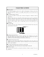
USAGE PRECAUTIONS


Handle carefully 

Do  not  drop  the  equipment  or  allow  it to  be  subject  to  strong  impact  or  vibration,  as  such  action 

may  cause  malfunctions.  Further,  do  not  damage  connected  cables,  since  this  may  cause  wire 

breakage.


Environmental operating conditions 

Do  not  use  the  product  in  locations  where  the  ambient  temperature  or  humidity  exceeds  the 

specifications.   

Otherwise,  image  quality  may  be  degraded  or  internal  components  may  be  adversely  affected.  In 

particular,  do  not  use  the  product  in  areas  exposed  to  direct  sunlight.  Moreover,  during  shooting 

under high temperatures, vertical stripes or white spots (noise) may be produced, depending on the 

subject  or  camera  conditions  (such  as  increased  gain).  However,  such  phenomena  are  not 

malfunctions.


About lens mount 

As  for  the  C-mount  lens  used  combining  this  camera,  the  projection  distance  from  bottom  of  the 

screw should use 8.8 mm or less. 

9.4mm or less

C-mount lens

Bottom of the screw


Combination check with the lens 
This  camera  might  from  a  ghost  to  image  area  depending  on  the  combination  of  a  lens  and  an 
illumination  with  this  camera.  But  this  is  not  a  failure  of  this  camera.  Therefore,  Please  check  the 
combination of the lens and the illumination with this camera when you use.


Combination check with the monitor 

Depending on a used monitor and the combination of the DVI-D cable, there is the case that is not 

displayed  normally  by  a  monitor.  Please  confirm  the  combination  of  a  monitor  and  DVI-D  cable 

and this camera beforehand.


Do not apply image pickup surface to the direct sun or intense light 

The color filter of the sensor fades when I guess strong light right for a long time.


Occurrence of moiré 

If  you  shoot  thin  stripe  patterns,  moiré  patterns  (interference  fringes)  may  appear.  This  is  not  a 

malfunction.


8.8mm or less 

Summary of Contents for CSDW2M60CM28

Page 1: ...ATIONS TABLE OF CONTENTS RESTRICTION FOR USE 1 CASES FOR INDEMNITY 2 USAGE PRECAUTIONS 3 1 INTRODUCTION 5 2 FEATURES 5 3 COMPONENT 6 4 OPTIONAL PARTS 6 5 FUNCTION 7 6 SPECIFICATION 10 7 GUARANTEE 17 8 SERVICE 17 9 APPEARANCE 18 Printed On Recycled Paper ...

Page 2: ...rformance and safety of the equipment or devices This product is not designed or manufactured to be used for control of equipment directly concerned with human life 1 or equipment relating to maintenance of public services functions involving factors of safety 2 Therefore the product shall not be used for such applications 1 Equipment directly concerned with human life refers to Medical equipment ...

Page 3: ... observe the information contained in the instructions in this instruction manual and specifications In the case damage or losses are caused by use contrary to the instructions in this instruction manual and specifications In the case damage or losses are caused by malfunction or other problems resulting from use of equipment or software that is not specified In the case damage or losses are cause...

Page 4: ... lens used combining this camera the projection distance from bottom of the screw should use 8 8 mm or less 9 4mm or less C mount lens Bottom of the screw Combination check with the lens This camera might from a ghost to image area depending on the combination of a lens and an illumination with this camera But this is not a failure of this camera Therefore Please check the combination of the lens ...

Page 5: ... or discolor the paint and indications If the image pickup surface becomes dusty contaminated or scratched consult your sales representative Precaution in the power supply from camera control connector There is the case that noise appears depending on a PC Then please use the DC12V supply from a power supply connector There is a possibility that the camera malfunction according to falling supply v...

Page 6: ...s superior in color reproduction characteristics because the sensor is adopted a primary color mosaic filter 3 DVI D The picture output is possible just to be connected to the monitor directly because the picture output is DVI D 4 Small and light This camera is small and light 5 Camera control It is possible to control this camera from camera control connector 6 Electronic lines It is possible to ...

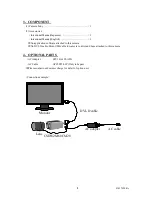
Page 7: ...software attached to this camera No DVI D cable Mini USB cable for camera control and Lens attached to this camera 4 OPTIONAL PARTS AC Adapter SPU16A 105 ASN AC Cable APC1025 01P Only in Japan Please contact our business charge for detail of option unit Connection example Monitor DVI D cable CSDW2M60CM28 Lens AC adapter AC cable ...

Page 8: ...ject It is possible to setting max gain of this time It is possible to change detect ratio Peak Average in AUTO mode 4 White balance There are 4 kinds of modes of MWB Manual White Balance OPWB One Push White Balance AWB Auto White Balance and PresetWB Preset White Balance It is possible to choose it to a subject a use Factory setting OPWB MWB Manual White Balance R gain and B gain can be set indep...

Page 9: ...reasonable photography When you use Auto Iris control please use the power supply from the AC adapter It is possible to work with DC control lens only Recommendation lens DV10 8SA SA1L FUJIFILM 8 Mirror mode It is possible to turn over the output picture It is possible to change ON OFF each Horizontal and Vertical 9 Electronic line Because it is possible to show a monitor screen electronic lines b...

Page 10: ...pe Translucent Grid interval Vertical 4 1920 Horizontal 4 1080 Grid Width 1 pixel Grid color Changeable 11 Color matrix It is possible to adjust the color masking manually The adjustment method is changing possibility in RGB and YUV Factory setting RGB RGB The variable parameter is R G R B G B G R B R and B G YUV The variable parameter is hue and saturation u v ...

Page 11: ... Output clock rate 148 352 MHz Horizontal 67 43 kHz Vertical 59 94 Hz 1920 1080 60i Output clock rate 74 176MHz Horizontal 33 72 kHz Vertical 29 97 Hz 6 Standard sensitivity 2000lx F4 5000K 7 Minimum sensitivity 24 lx F1 4 gain 12dB gamma 16 video level 50 8 Gain MANU AUTO change Fatory setting AUTO MANU Manual gain control Corrective range 6dB 12dB Fatory setting 0dB AUTO Auto gain control Detect...

Page 12: ...6500K 11 Gamma 17 step Change Fatory setting 5 0 Correction OFF γ 1 1 16 Correction ON 12 Aperture 8 Step change each High frequency and Low frequency Fatory setting 3 0 Correction OFF 1 7 Correction ON 13 Mirror mode Horizontal turn ON OFF change Fatory setting OFF Vertical turn ON OFF change Fatory setting OFF 14 Electronic line ON OFF change Fatory setting OFF Number Vertical Horizontal each 2 ...

Page 13: ...th DC cable and Mini USB cable for camera control were connected 12V from DC cable is given priority A note There is a possibility that the camera malfunction according to falling supply voltage depending on a Mini USB cable for camera control to use In that case please use the DC12V supply from a power supply connector 17 Power consumption Approx 2 5W ...

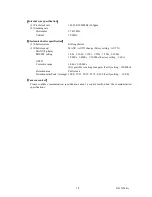
Page 14: ...ing AUTO MANU 9 phase PRESET setting 1 60s 1 100s 1 120s 1 250s 1 500s 1 1000s 1 2000s 1 4000s 1 10 000s Factory setting 1 60s AUTO Corrective range 1 60s 1 10 000s It is possible to setting max gain Factly setting 1 10 000s Detection area Full screen Detection ratio Peak Average 100 0 75 25 50 50 25 75 0 100 Factly setting 100 0 Camera control Please confirm communication specifications about a c...

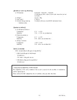
Page 15: ...ion assurance Temperature 0 C 40 C Humidity 90 or less no condensation 3 Storage assurance Temperature 20 C 60 C Humidity 90 or less no condensation Safety standards EMC standard Electro Magnetic Compatibility EMI Electro Magnetic Interference EN61000 6 3 FCC Part 15 Subpart B class A EMS Electro Magnetic Susceptibility EN61000 6 2 A request about adaptability of EMC standard The adaptability of t...

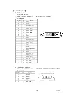
Page 16: ... N C 9 O TX1 10 O TX1 11 TX1 3 Shield 12 TX3 N C 13 TX3 N C 14 5V 15 GND 16 I Hot Plug Detect 17 O TX0 18 O TX0 19 TX0 5 Shield 20 TX5 N C 21 TX5 N C 22 O TX Clock Shield 23 O TX Clock 24 O TX Clock 2 Camera control connector Connector model Camera side UX60SC MB 5ST 80 HIROSE ELECTRIC Pin assignment Pin No I O Function 1 POWER 2 I O USB D 3 I O USB D 4 N C 5 USB_GND 1 2 3 4 5 6 7 8 9 10 24 11 12 ...

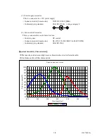
Page 17: ... auto Iris lens Control system DC control Connector model Camera side D4 157J 250 TECHNICAL ELECTRON Conformity plug standard EIAJ RC 5204 Spectral Sensitivity Characteristic The lens characteristics and light source characteristics is not reflected in table It includes an IR cut filter characteristic Relative response curves 0 10 20 30 40 50 60 70 80 90 100 400 450 500 550 600 650 700 Wave length...

Page 18: ...odeling The trouble because of a fall after the purchase and transportation The trouble because of fire natural calamity earthquake storm and flood damage thunderbolt damage from salty breeze gas harm and abnormal voltage 8 SERVICE 1 Condition for repair When the user requests us to repair product please return it our factory and we repair it But user bear overheads travel expenses a cost of camer...

Page 19: ...18 D4176244A 9 APPEARANCE ...

Page 20: ...l Business Department Phone 81 42 589 8771 Fax 81 42 589 8774 URL http www toshiba teli co jp Distributor This product must be classified for disposal according to the laws of each country and municipal laws Information contained in this document is subject to change without prior notice ...

Reviews: