background image

17

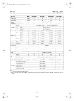
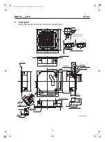
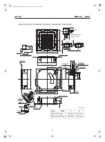
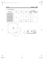
MMU-AP___2H2UL

E15-3C1

10. Accessories

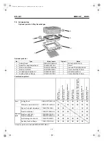
Optional parts for 4-Way Cassette type

Optional parts list

Combination pattern

*All option part is not used with MMU-AP0072H2UL-1.

No

Type

Model name

Qty/unit

Notes

1

Ceiling Panel

RBC-U31PG(W)-UL

1

White (2.5GY9.0/0.5)

2

Spacer for height adjustment

TCB-SP1602UUL

1

50 mm

3

Fresh-air chamber

TCB-GFC1602UUL

1

Use with TCB-GB1602UUL

4

Fresh-air inlet box

TCB-GB1602UUL

1

Connection=Dia.100 mm

5

Air-discharge direction kit

TCB-BC1602UUL

1

6-direction patterns

6

Auxiliary fresh air flange

TCB-FF101URUL

1

Connection=Dia.100 mm

Ceiling Panel

RBC-

U

31PG(

W)

-U

L

W

ireles

s rem

ote c

ontro

l k

it

R

B

C

-AX31U

(W

)-U

L

Sp

acer for heig

ht

 adjustment


TCB

-SP1602UUL

Fresh-air chamber

TCB

-GFC1602UUL

Fresh-air inlet

 box 

+ Fresh-a

ir 

chamber

TCB

-GB1 

TCB-G

FC1602UUL

Air-discharge direct

ion kit

TCB

-BC1

602UUL

Auxiliary fresh air

 flange

TCB

-FF101URUL

Panel

Ceiling Panel

RBC-U31PG(W)-UL

OK

OK

OK

OK

OK

OK

Wireless remote control kit

RBC-AX31U(W)-UL

OK

OK

OK

OK

OK

OK

Optional 
parts

Spacer for height adjustment

TCB-SP1602UUL

OK

OK

OK

OK

OK

Fresh-air chamber

TCB-GFC1602UUL

OK

OK

OK

OK

OK

Fresh-air inlet box + 

Fresh-air chamber

TCB-GB1

TCB-GFC1602UUL

OK

OK

OK

OK

Air-discharge direction kit

TCB-BC1602UUL

OK

OK

OK

OK

OK

OK

Auxiliary fresh air flange

TCB-FF101URUL

OK

OK

OK

OK

OK

OK

4

3

5

6

2

1

+00E15-3C1_01EN.book  Page 17  Thursday, March 24, 2016  11:25 AM

Summary of Contents for Carrier MMU-AP0182H2UL

Page 1: ... Electrical current characteristics 7 Sensible capacity table 8 Air throw distance chart 9 Sound data 10 Accessories 11 Reference MMU AP0072H2UL MMU AP0092H2UL MMU AP0122H2UL MMU AP0152H2UL MMU AP0182H2UL MMU AP0212H2UL MMU AP0242H2UL MMU AP0302H2UL MMU AP0362H2UL MMU AP0422H2UL MMU AP0072H2UL 1 00E15 3C1_01EN book Page 1 Thursday March 24 2016 11 25 AM ...

Page 2: ...33 1 37 4 Packing Height In 11 3 3 9 11 3 3 9 11 3 3 9 11 3 3 9 11 3 3 9 11 3 3 9 11 3 3 9 Width In 36 0 39 8 36 0 39 8 36 0 39 8 36 0 39 8 36 0 39 8 36 0 39 8 36 0 39 8 Depth In 37 2 39 8 37 2 39 8 37 2 39 8 37 2 39 8 37 2 39 8 37 2 39 8 37 2 39 8 Total weight Ceiling panel Unit lbs 42 10 42 10 46 10 46 10 46 10 48 10 48 10 Packed unit lbs 51 15 5 51 15 5 55 15 5 55 15 5 55 15 5 57 15 5 57 15 5 H...

Page 3: ... 1 37 4 Packing Height In 11 3 3 9 13 8 3 9 13 8 3 9 11 3 3 9 Width In 36 0 39 8 36 0 39 8 36 0 39 8 36 0 39 8 Depth In 37 2 39 8 37 2 39 8 37 2 39 8 37 2 39 8 Total weight Ceiling panel Unit lbs 48 10 59 10 59 10 46 10 Packed unit lbs 57 15 5 69 15 5 69 15 5 55 15 5 Heat exchanger Finned tube Fan unit Fan Turbo fan Standard air flow High Mid Low cfm 730 630 510 1160 840 630 1250 840 670 550 490 4...

Page 4: ...840 Unit external dimension 10 6 269 16 1 408 Ceiling bottom surface 4 4 112 6 8 172 1 7 42 2 3 58 9 5 241 5 1 6 40 9 9 251 11 1 281 12 0 306 4 2 106 5 2 8 72 Hole for remote controller wires Conduit hole Knockout Ceiling bottom surface Hole for power supply cable Refrigerant pipe connecting port Liquid Ø 1 4 6 4 Refrigerant pipe connecting port Gas Ø 3 8 9 5 Knockout for simple OA For 3 9 100 27 ...

Page 5: ...or remote controller wires Conduit hole Knockout Ceiling bottom surface Hole for power supply cable Refrigerant pipe connecting port Liquid A Refrigerant pipe connecting port Gas B Knockout for simple OA For 3 9 100 27 2 0 8 690 Hanging bolt pitch 33 1 840 Unit external dimension 39 4 1000 or more Space required for installation 0 6 15 or more 39 4 1000 or more 0 6 15 or more 39 4 1000 or more 7 9...

Page 6: ...ain pipe connecting port 2 3 58 1 6 40 9 9 251 11 1 281 12 0 306 Hole for remote controller wires Conduit hole Knockout Hole for power supply cable 45 Refrigerant pipe connecting port Liquid 3 8 9 5 Refrigerant pipe connecting port Gas 5 8 15 9 27 2 0 8 690 Hanging bolt pitch Knockout for simple OA For 3 9 100 39 4 1000 or more Space required for installation 0 6 15 or more 39 4 1000 or more 39 4 ...

Page 7: ...s Ceiling panel lbs MMU AP0072H2UL 18 5 17 9 6 05 42 10 MMU AP0092H2UL MMU AP0122H2UL 46 MMU AP0152H2UL MMU AP0182H2UL MMU AP0212H2UL 48 MMU AP0242H2UL MMU AP0302H2UL MMU AP0362H2UL 17 7 7 25 59 MMU AP0422H2UL MMU AP0072H2UL 1 17 9 6 05 46 00E15 3C1_01EN book Page 7 Thursday March 24 2016 11 25 AM ...

Page 8: ...Piping diagram Air heat exchanger at indoor side Sensor TC2 㹋 Fan Fan Motor Sensor TCJ Sensor TC1 Strainer Pulse Motor Valve Liquid side Gas side Capillary Tube Sensor TA 00E15 3C1_01EN book Page 8 Thursday March 24 2016 11 25 AM ...

Page 9: ...䏗䏈䏖䎃 䏗䏋䏈䎃 䏗䏈䏕䏐䏌䏑䏄䏏䎃 䏅䏏䏒䏆䏎䎑 䎃 䎃 䎃 䎃 䎯䏈䏗䏗䏈䏕䎃 䏄䏗䎃 䏌䏑䏖䏌䏇䏈䎃 䏌䏑䏇䏌䏆䏄䏗䏈䏖䎃 䏗䏋䏈䎃 䏗䏈䏕䏐䏌䏑䏄䏏䎃 䏑䏘䏐䏅䏈䏕䎑 䎤䎃 䏇䏒䏗䏗䏈䏇䎃 䏏䏌䏑䏈䎃 䏄䏑䏇䎃 䏅䏕䏒䏎䏈䏑䎃 䏏䏌䏑䏈䎃 䏌䏑䏇䏌䏆䏄䏗䏈䎃 䏗䏋䏈 䎃 䎃 䎃 䎃 䏚䏌䏕䏌䏑䏊䎃 䏄䏗䎃 䏖䏌䏗䏈䎑 䎃 䏌䏑䏇䏌䏆䏄䏗䏈䏖䎃 䏗䏋䏈䎃 䏆䏒䏑䏗䏕䏒䏏䎃 䎳䎑䎦䎑䏅䏒䏄䏕䏇䎑 䎵䎨䎧䎝䎵䎨䎧 䎺䎫䎬䎝䎺䎫䎬䎷䎨 䎼䎨䎯䎝䎼䎨䎯䎯䎲䎺 䎥䎯䎸䎝䎥䎯䎸䎨 䎥䎯䎮䎝䎥䎯䎤䎦䎮 䎪䎵䎼䎝䎪䎵䎤䎼 䎳䎱䎮䎝䎳䎬䎱䎮 䎲䎵䎱䎝䎲䎵䎤䎱䎪䎨 䎪䎵䎱䎝䎪䎵䎨䎨䎱 䎥䎵䎺䎝䎥䎵䎲䎺䎱 䎦䎲䎯䎲䎵 䎬䎧䎨䎱䎷䎬䎩䎬䎦䎤䎷䎬䎲䎱 00E15 3C1_01EN book Page 9 Thursday March 24 2016 11 25 AM ...

Page 10: ... 0 021 0 6 0 8 15 MMU AP0122H2UL 208 230 1 60 187 253 0 023 0 6 0 8 15 MMU AP0152H2UL 208 230 1 60 187 253 0 026 0 6 0 8 15 MMU AP0182H2UL 208 230 1 60 187 253 0 026 0 6 0 8 15 MMU AP0212H2UL 208 230 1 60 187 253 0 036 0 8 1 0 15 MMU AP0242H2UL 208 230 1 60 187 253 0 036 0 8 1 0 15 MMU AP0302H2UL 208 230 1 60 187 253 0 043 0 8 1 0 15 MMU AP0362H2UL 208 230 1 60 187 253 0 088 1 0 1 3 15 MMU AP0422H...

Page 11: ...6920 10060 6860 10520 6700 102 7390 5990 8180 6390 8740 6790 9010 6760 9280 6760 9820 6700 10270 6540 012 50 9850 7690 10900 8190 11640 8700 12000 8670 12360 8670 13080 8590 13680 8390 54 9850 7690 10900 8190 11640 8700 12000 8670 12360 8670 13080 8590 13680 8390 57 9850 7690 10900 8190 11640 8700 12000 8670 12360 8670 13080 8590 13680 8390 61 9850 7690 10900 8190 11640 8700 12000 8670 12360 8670 ...

Page 12: ...50 14880 70 17870 14150 18700 14540 19880 15130 21000 15610 21360 15650 22710 15450 23650 14880 73 17870 14150 18700 14540 19880 15130 21000 15610 21360 15650 22710 15450 23650 14880 77 17870 14150 18700 14540 19880 15130 21000 15610 21360 15650 22710 15450 23650 14880 81 17870 14150 18700 14540 19880 15130 21000 15610 21360 15650 22710 15450 23650 14880 84 17870 14150 18700 14540 19880 15130 2100...

Page 13: ...000 36000 24750 36620 24820 38930 24500 40540 23590 70 30640 22440 32060 23060 34090 24000 36000 24750 36620 24820 38930 24500 40540 23590 73 30640 22440 32060 23060 34090 24000 36000 24750 36620 24820 38930 24500 40540 23590 77 30640 22440 32060 23060 34090 24000 36000 24750 36620 24820 38930 24500 40540 23590 81 30640 22440 32060 23060 34090 24000 36000 24750 36620 24820 38930 24500 40540 23590 ...

Page 14: ... 0 7 m s 1 64 ft s 0 5 m s 0 98 ft s 0 3 m s 0 0 3 28 1 6 56 2 9 84 3 0 2 3 ft s 0 7 m s 1 64 ft s 0 5 m s 0 98 ft s 0 3 m s MMU AP0212H2UL AP0242H2UL AP0302H2UL 0 3 28 1 6 56 2 9 84 3 16 4 5 13 1 4 3 28 1 6 56 2 Adv wind speed 17 7 ft s 5 4 m s Ceiling height ft m Horizontal distance ft m Horizontal distance ft m Adv wind speed 30 8 ft s 9 4 m s Ceiling height ft m 14 8 4 5 3 28 1 6 56 2 9 84 3 M...

Page 15: ...5 33 31 Sound pressure level dB A 10 20 30 40 50 60 70 80 90 63 125 250 500 1000 2000 4000 8000 Octave band center frequency Hz Octave band sound pressure level dB H M L NC 70 NC 60 NC 50 NC 40 NC 30 NC 20 Audibility limits of continuous white level MMU AP0212H2UL AP0242H2UL 10 20 30 40 50 60 70 80 90 63 125 250 500 1000 2000 4000 8000 Octave band center frequency Hz Octave band sound pressure lev...

Page 16: ... level dB A 63 125 250 500 1000 2000 4000 8000 Octave band center frequency Hz H M L MMU AP0362H2UL 63 125 250 500 1000 2000 4000 8000 Octave band center frequency Hz Octave band sound pressure level dB NC 70 NC 60 NC 50 NC 40 NC 30 NC 20 10 20 30 40 50 60 70 80 90 H M L 46 40 5 36 5 Sound pressure level dB A H M L Audibility limits of continuous white level 00E15 3C1_01EN book Page 16 Thursday Ma...

Page 17: ...31PG W UL Wireless remote control kit RBC AX31U W UL Spacer for height adjustment TCB SP1602UUL Fresh air chamber TCB GFC1602UUL Fresh air inlet box Fresh air chamber TCB GB1602UUL TCB GFC1602UUL Air discharge direction kit TCB BC1602UUL Auxiliary fresh air flange TCB FF101URUL Panel Ceiling Panel RBC U31PG W UL OK OK OK OK OK OK Wireless remote control kit RBC AX31U W UL OK OK OK OK OK OK Optiona...

Page 18: ...d for installation Unit in mm 39 4 1000 or more 39 4 1000 or more Ceiling bottom surface Refrigerant pipe connecting port Gas Refrigerant pipe connecting port Liquid Drain pipe connecting port 30 6 778 29 3 745 A 11 3 288 0 6 15 or more 0 6 15 or more 9 0 228 10 7 271 8 3 211 4 4 112 1 2 30 30 6 778 33 3 846 29 3 745 27 8 705 24 8 630 27 8 705 24 8 630 00E15 3C1_01EN book Page 18 Thursday March 24...

Page 19: ...ting material B Shield plate assembly 3 Duct flange 4 Mounting screws 1 Outside air introduction port 2 Outside air introduction port fixing metal part 4 Mounting screws 7 Wind shield 4 Mounting screws After installing the panel fix the wind shield 7 with the mounting screws 4 4 8 Ø 1 2 3 3 8 Ø97 3 5 90 4 3 108 37 4 950 3 0 77 3 7 95 2 6 65 0 4 11 5 7 144 5 9 150 3 9 98 1 4 35 1 8 45 8 5 216 37 4 ...

Page 20: ...available by using the booster fan 1 Fresh air inlet box with Fresh air chamber Up to 88 cfm and 10 of rated air volume 2 Auxiliary fresh air flange through the knock out hole of the indoor unit body Up to 24 cfm Inter lock circuit 1 Connect the driving relay of the duct fan DC 12 V between 1 and 6 on the indoor P C board Part indicated with a bold line is the connecting circuit After installation...

Page 21: ... screws Duct fan In order to take fresh air provide the duct fan separately 1 Install the filter for fresh air 2 Provide the check port beneath the duct fan for maintenance 3 Connect the duct fan and the indoor unit with inter lock wiring 4 Provide the silencer to prevent the effect of noise Dimension MMU AP0072H2UL 1 is not used Cut off the steel plate with cutting pliers or the like 4 places Cut...

Page 22: ...or Moon white 2 0 50 37 8 960 39 4 1000 or more 0 6 15 or more 0 6 15 or more 39 4 1000 or more 39 4 1000 or more Space required for installation Refrigerant pipe connecting port Gas Refrigerant pipe connecting port Liquid Drain pipe connecting port A 5 5 139 3 1 79 2 0 50 3 1 80 2 4 62 4 8 122 Ceiling bottom surface Unit in mm 00E15 3C1_01EN book Page 22 Thursday March 24 2016 11 25 AM ...

Page 23: ...for all models Available only for 007 to 030 type Available only for 036 to 042 type 2 way air flow Available for all models Available for all models Available for all models Wind shield C Wind shield A Wind shield B Wind shield A Wind shield A Wind shield B Wind shield A Wind shield C Wind shield B Wind shield C 00E15 3C1_01EN book Page 23 Thursday March 24 2016 11 25 AM ...

Page 24: ...anch 042 type 3 directions 1 branch 036 type 3 directions 2 branches 042 type 3 directions 2 branches 0 0 04 10 0 08 20 0 12 30 0 16 40 0 20 50 0 24 60 0 28 70 0 32 80 0 36 90 412 700 58 9 100 118 200 177 300 235 400 294 500 353 600 1 2 3 5 4 6 Install the cover Use air discharge direction kit TCB BC1602UUL to cover the air discharge port 4 51 114 6 4 13 105 4 51 114 6 4 13 105 45 45 Ø6 46 162 4 Ø...

Page 25: ...MEMO 00E15 3C1_01EN book Page 1 Thursday March 24 2016 11 25 AM ...

Page 26: ...MEMO 00E15 3C1_01EN book Page 2 Thursday March 24 2016 11 25 AM ...

Page 27: ...MEMO 00E15 3C1_01EN book Page 3 Thursday March 24 2016 11 25 AM ...

Page 28: ...4 Way Cassette type Engineering Data Book Model name MMU AP___2H2UL AP___2H2UL 1 March 2016 First Edition 00E15 3C1_01EN book Page 1 Thursday March 24 2016 11 25 AM ...

Reviews: