Toshiba Carrier MMD-AP0074SPH2UL Installation Manual Download Page 4

– 3 –

3

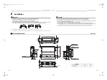
Selection of installation place

Avoid installing in the following places

Select a location for the indoor unit where the cool or warm air will circulate evenly.
Avoid installation in the following kinds of locations.
• Saline area (coastal area).
• Locations with acidic or alkaline atmospheres (such as areas with hot springs, factories where chemicals or 

pharmaceuticals are made and places where the exhaust air from combustion appliances will be sucked into the 
unit). 
Doing so may cause the heat exchanger (its aluminum fins and copper pipes) and other parts to become 
corroded.

• Locations with atmospheres with mist of cutting oil or other types of machine oil. 

Doing so may cause the heat exchanger to become corroded, mists caused by the blockage of the heat 
exchanger to be generated, the plastic parts to be damaged, the heat insulators to peel off, and other such 
problems to result.

• Locations where vapors from food oils are formed (such as kitchens where food oils are used). 

Blocked filters may cause the air conditioner’s performance to deteriorate, condensation to form, the plastic parts 
to be damaged, and other such problems to result.

• Places where iron or other metal dust is present. If iron or other metal dust adheres to or collects on the interior 

of the air conditioner, it may spontaneously combust and start a fire.

• Locations near obstructions such as ventilation openings or lighting fixtures where the flow of the blown air will 

be disrupted (a disruption of the air flow may cause the air conditioner’s performance to deteriorate or the unit to 
shut down).

• Locations where an in-house power generator is used for the power supply.

The power line frequency and voltage may fluctuate, and the air conditioner may not work properly as a result.

• On truck cranes, ships or other moving conveyances.
• The air conditioner must not be used for special applications (such as for storing food, plants, precision 

instruments or art works).
(The quality of the items stored may be degraded.)

• Locations where high frequencies are generated (by inverter equipment, in-house power generators, medical 

equipment or communication equipment).
(Malfunctioning or control trouble in the air conditioner or noise may adversely affect the equipment’s operation.)

• Locations where there is anything under the unit installed that would be compromised by wetness.

(If the drain has become blocked or when the humidity is over 80 %, condensation from the indoor unit will drip, 
possibly causing damage to anything underneath.)

• In the case of the wireless type of system, rooms with the inverter type of fluorescent lighting or locations 

exposed to direct sunlight.
(The signals from the wireless remote control may not be sensed.)

• Locations where organic solvents are being used.
• The air conditioner cannot be used for liquefied carbonic acid cooling or in chemical plants.
• Location near doors or windows where the air conditioner may come into contact with high-temperature, high-

humidity outdoor air.
(Condensation may occur as a result.)

• Locations where special sprays are used frequently.

„

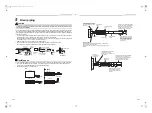
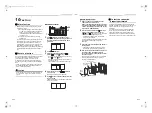
Installation under high-humidity atmosphere

In some cases including the rainy season, especially inside of the ceiling may become high-humidity atmosphere 
(dew-point temperature: 73 °F (22.8 °C) or higher).
1. Installation to inside of the ceiling with tiles on the roof
2. Installation to inside of the ceiling with slated roof
3. Installation to a place where inside of the ceiling is used for pathway to intake the fresh air
4. Installation to a kitchen
• In the above cases, additionally attach the heat insulator to all positions of the air conditioner, which come to 

contact with the high-humidity atmosphere. In this case, arrange the side plate (Check port) so that it is easily 
removed.

• Apply also a sufficient heat insulation to the duct and connecting part of the duct.

„

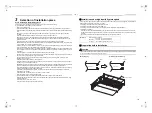
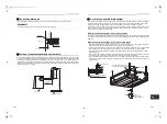
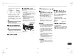
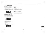
Preparation before installation

CAUTION

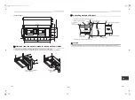
The air intake port flange is attached upside down for product protection during shipping. Be sure to reattach the flange 
in the correct orientation in order to connect to the duct.

[Reference]

Condensation test conditions

Indoor side: 80 °F (26.7 °C) dry bulb temperature 

75 °F (23.9 °C) wet bulb temperature

Air volume:

Low air volume, operation time 4 hours

During shipping

To install (correct orientation)

Flange

Flange

Indoor unit

Indoor unit

Screw (10 pieces)

5-EN

6-EN

+00EH99885401.book  Page 3  Friday, March 2, 2012  11:01 AM

Summary of Contents for Carrier MMD-AP0074SPH2UL

Page 1: ... Slim Duct Type MMD AP0074SPH2UL MMD AP0094SPH2UL MMD AP0124SPH2UL MMD AP0154SPH2UL MMD AP0184SPH2UL AIR CONDITIONER MULTI TYPE Installation Manual Manuel d installation 22 Français Installation Manual 1 English 00EH99885401 book Page 1 Friday March 2 2012 11 01 AM ...

Page 2: ...fire Do not use any refrigerant different from the one specified for complement or replacement Otherwise abnormally high pressure may be generated in the refrigeration cycle which may result in a failure or explosion of the product or an injury to your body Connect ground wire grounding work Incomplete grounding may cause an electric shock Do not connect ground wires to gas pipes water pipes light...

Page 3: ... circuit breaker is he or she will not be able to turn it off in the event that trouble has occurred in the air conditioner CAUTION This air conditioner adopts the new HFC refrigerant R410A which does not destroy ozone layer The characteristics of R410A refrigerant are easy to absorb water oxidizing membrane or oil and its pressure is approx 1 6 times higher than that of refrigerant R22 Accompanie...

Page 4: ...cal equipment or communication equipment Malfunctioning or control trouble in the air conditioner or noise may adversely affect the equipment s operation Locations where there is anything under the unit installed that would be compromised by wetness If the drain has become blocked or when the humidity is over 80 condensation from the indoor unit will drip possibly causing damage to anything undern...

Page 5: ...ir filter when you attach it Under air intake Back air intake Air discharge 3 9 100 or more 15 8 400 or more 0 2 5 or more 8 3 210 0 2 5 or more 11 2 285 or more 8 3 210 3 9 100 or more Air intake Ceiling Ceiling 11 8 300 or more Air intake 0 2 5 or more 9 3 235 or more 8 3 210 Service space Unit in mm Reserve sufficient space required for installation or service work Filter cleaning sign term set...

Page 6: ...her material to not damage the unit To move the indoor unit hold the hooking brackets 4 positions only Do not apply force to the other parts refrigerant pipe drain pan foamed parts resin parts or other parts Carry the package by two or more persons and do not bundle it with plastic band at positions other than specified To install vibration isolation material to hanging bolts confirm that it does ...

Page 7: ...tallation of the wired remote control refer to the instructions that are supplied with the control The connection point for the control wiring and the entrance point for the control wiring are clearly marked in the instructions Hanging bolt W3 8 M10 4 pieces Nut W3 8 M10 12 pieces Nut W3 8 M10 M10 flat washer Accessory M10 flat washer Accessory Hanging bolt W3 8 M10 Nut W3 8 M10 Set the air intake...

Page 8: ... the flexible hose on a horizontal level 4 11 to 6 7 1 5 to 2 m Support bracket Downward slope 1 100 or more Arched shape Trap Downward slope 1 100 or more Collective piping As long as possible Approx 3 9 100 mm Heat insulator Incorrect VP30 OK NO GOOD max 45 max 45 90 Bend Riser Trap Top view Side view Side view Air discharge Side view Air discharge Air discharge Adhesive inhibited Use the attach...

Page 9: ...the pipes When doing this also check that no abnormal sounds are heard from the drain pump motor Check draining also when installed in heating period When the electrical and wiring work has been completed Pour some water by following the method shown in the following figure Then while performing a cooling operation check that the water drains from the drain pipe connecting port transparent and tha...

Page 10: ... surface of the indoor unit Heat insulator locally procured Heat insulator of the drain connecting section Accessory Indoor unit 6 Duct design Arrangement Unit in mm Referring to the following dimensions manufacture duct at the local site Air discharge Back air intake 0 8 19 3 0 8 20 0 8 20 6 8 171 4 outside 0 8 19 30 Air discharge flange outside 31 7 805 Unit external dimension 33 3 845 2 2 57 8 ...

Page 11: ...it to the air intake side Take out this cover plate CAUTION Connecting method of the duct CAUTION Incomplete heat insulation of the supply air flange and sealing may occur dewing resulted in falling of water drop Flange Aluminum tape locally procured Aluminum tape locally procured Under surface Cover a screw Heat insulator with sticking material locally procured Aluminum tape locally procured Air ...

Page 12: ...pe is long provide support brackets at intervals of 8 2 to 9 10 2 5 to 3 m to clamp the refrigerant pipe Otherwise abnormal sound may be generated Use the flare nut attached with the indoor unit or R410A flare nut Permissible piping length and height difference They vary depending on the outdoor unit For details refer to the Installation Manual attached to the outdoor unit Pipe size Unit in mm Con...

Page 13: ...ic fire or malfunction 2 Connect ground wire grounding work Incomplete grounding cause an electric shock Do not connect ground wires to gas pipes water pipes lightning rods or ground wires for telephone wires 3 Install appliance in accordance with national wiring regulations Capacity shortage of circuit breaker or incomplete installation may cause an electric shock or a fire CAUTION Consult local ...

Page 14: ...rol inter unit wiring Wire size AWG20 Total wire length of remote control wiring and remote control inter unit wiring L L1 L2 Ln In case of wired type only Up to 1640 5 500 m In case of wireless type included Up to 1312 4 400 m Total wire length of remote control inter unit wiring L1 L2 Ln Up to 656 2 200 m L1 L L2 Ln Indoor unit Remote control inter unit wiring Indoor unit Indoor unit Indoor unit...

Page 15: ...l box Remove cover plate Conduit plate Conduit plate Bushing of control and remote control wires Conduit Electrical control box cover Hook Electrical control box cover fixed screw B A L L Ground screw Cord clamp Power supply wire and ground wire Control wire 2 core shielded wire Remote control wire Cord clamp Power supply wires and ground wire 1 Strip the wire ends Power supply wire 0 4 10 mm Grou...

Page 16: ...air conditioner or other trouble with the product may result 1 Push and hold button and TEMP button simultaneously for at least 4 seconds After a while the display flashes as shown in the figure Confirm that the CODE No is 01 If the CODE No is not 01 push button to clear the display content and repeat the procedure from the beginning No operation of the remote control is accepted for a while after...

Page 17: ... difficult to obtain satisfactory heating due to installation place of the indoor unit or structure of the room the detection temperature of heating can be raised Also use a circulator or other machinery to circulate heat air near the ceiling Follow to the basic operation procedure 1 2 3 4 5 6 For the CODE No in Procedure 3 specify 06 For the set data in Procedure 4 select the SET DATA of shift va...

Page 18: ...ed as usual 4 After the test run push button to stop a test run Display part is same as procedure 1 5 Push button to cancel release from the test run mode TEST disappears on the display and the status returns to a normal 2 4 3 1 5 Wireless remote control 1 Remove a small screw which fixes the nameplate of the receiver unit Remove the nameplate of the sensor section by inserting a flat blade screwd...

Page 19: ... or more the following display appears If Service check is displayed the mode enters in the error log mode 01 Order of error log is displayed in CODE No window Check code is displayed in CHECK window Indoor unit address in which an error occurred is displayed in Unit No Procedure 2 Push button The error log stored in memory is displayed in order The numbers in CODE No indicate CODE No 01 latest 04...

Page 20: ...connected indoor units Combined capacity of indoor units exceeds 120 of combined capacity of outdoor units I F E18 Communication error between indoor units Indoor E19 E19 00 Header is nothing 02 Two or more header units Outdoor header units quantity error I F E20 E20 01 Outdoor of other line connected 02 Indoor of other line connected Other line connected during automatic address I F E23 E23 Sendi...

Page 21: ...display Outdoor 7 segment display Sensor block display of receiving unit Auxiliary code Operation Timer Ready Flash A3 IPDU Fan IPDU 1 2 3 01 c 02 c 03 c c 04 c 05 c c 06 c c 07 c c c 08 c 09 c c 0A c c 0B c c c 0C c c 0D c c c 0E c c c 0F c c c c c IPDU error Error detected by TCC LINK central control device TCC LINK TOSHIBA Carrier Communication Link P18 P18 ALT Discharge temp TD3 error I F P19 ...

Page 22: ...ting systems in a single refrigerating device the amounts of refrigerant should be as charged in each independent device For the amount of charge in this example The possible amount of leaked refrigerant gas in rooms A B and C is 22 lbs 10 kg The possible amount of leaked refrigerant gas in rooms D E and F is 33 lbs 15 kg NOTE 2 The standards for minimum room volume are as follows 1 No partition s...

Page 23: ...cien d entretien qualifié Une installation incorrecte peut entraîner des fuites d eau une électrocution ou un incendie N utilisez pas un fluide frigorigène différent de celui spécifié pour le complément ou le remplacement Faute de quoi une pression anormalement élevée risque d être générée dans le circuit de réfrigération ce qui peut entraîner une panne ou une explosion du produit ou vous pouvez v...

Page 24: ...urviendrait au niveau du climatiseur PRÉCAUTION Ce climatiseur utilise le nouveau refrigerant HFC R410A qui ne detruit pas la couche d ozone Le fluide frigorigène R410A se distingue par son absorption aisée de l eau de la membrane oxydante ou de l huile ainsi que par sa pression qui est d environ 1 6 fois celle du fluide frigorigène R22 Outre l utilisation du nouveau fluide frigorigène l huile réf...

Page 25: ...ication Un dysfonctionnement un mauvais contrôle du climatiseur ou un bruit au niveau de ce dernier pourrait nuire au bon fonctionnement de l équipement Les endroits dans lesquels le climatiseur serait installé au dessus d objets que l humidité pourrait détériorer Si la conduite de vidange est obstruée ou si le taux d humidité est supérieur à 80 la condensation provenant de l unité intérieure se m...

Page 26: ... filtre à air quand vous l attachez Sous une admission d air Admission d air à l arrière Evacuation d air 3 9 100 ou plus 15 8 400 ou plus 0 2 5 ou plus 8 3 210 0 2 5 ou plus 11 2 285 ou plus 8 3 210 3 9 100 ou plus Entrée d air Plafond Plafond 11 8 300 ou plus Entrée d air 0 2 5 ou plus 9 3 235 ou plus 8 3 210 Espace de service Unité po mm Prévoyez suffisamment d espace pour l installation ou l e...

Page 27: ...ransport et de manipulation Pour déplacer l unité intérieure tenez seulement les crochets 4 points N exercez aucune force sur les autres pièces tuyau de réfrigération bac de récupération parties isolantes parties en résine etc Portez l emballage à deux personnes ou plus et ne l empaquetez pas avec du ruban adhésif sur des points autres que ceux qui sont spécifiés Avant d appliquer le matériau d is...

Page 28: ...écommande câblée reportez vous aux instructions fournies avec la commande Le point de connexion pour le câblage de la télécommande et le point d entrée pour le câblage de télécommande sont clairement marqués dans le manuel d instructions Boulon de suspension W3 8 M10 4 pièces Ecrou W3 8 M10 12 pièces Ecrou W3 8 M10 Rondelle plate M10 Accessoire Rondelle plate M10 Accessoire Boulon de suspension W3...

Page 29: ...rage fourni Utilisez ce flexible en position horizontale 4 11 à 6 7 1 5 à 2 m Support Inclinaison vers le bas de 1 100 ou plus En forme d arc Siphon Inclinaison vers le bas de 1 100 ou plus Tuyauterie Le plus long possible Approx 3 9 100 mm Isolant thermique Incorrect VP30 OK PAS BON max 45 max 45 Coude de 90 Colonne montante Siphon Vue de dessus Vue latérale Vue latérale Evacuation d air Vue laté...

Page 30: ... certifié pour un bon fonctionnement Pendant les essais vérifiez que l eau s évacue correctement et qu elle ne fuit pas par les raccords Lors de ce réglage vérifiez également qu aucun son anormal ne se produit au niveau du moteur de la pompe de vidange Vérifiez également l évacuation lors d une installation en période de chauffage Lorsque les opérations de câblage et de raccordement électrique son...

Page 31: ...olant thermique fourni en partant de la surface de l unité intérieure Isolant thermique vendue sur place Isolant thermique de la section de raccordement de la conduite de vidange Accessoire Unité intérieure 6 Conception de conduite Disposition Unité po mm Compte tenu des dimensions suivantes fabriquez les gaines sur site Evacuation d air Admission d air à l arrière 0 8 19 3 0 8 20 0 8 20 6 8 171 4...

Page 32: ...ette plaque de fermeture PRÉCAUTION Méthode de raccordement de la gaine PRÉCAUTION Si l isolation thermique de la bride de la conduite d amenée et du joint est insuffisante de l humidité peut apparaître et ainsi entraîner la formation de gouttes d eau Bride Bande en aluminium vendue sur place Bande en aluminium vendue sur place Surface inférieure Recouvrement de la vis Isolant thermique avec matér...

Page 33: ... longue posez des supports tous les 8 2 à 9 10 2 5 à 3 m pour assurer son maintien Autrement cela risque de provoquer un son anormal Utilisez l écrou évasé fixé à l unité intérieure ou l écrou évasé R410A Longueur de tuyau et différence de hauteur admissibles Elles varient selon le type d unité extérieure Pour de plus amples détails reportez vous au manuel d installation de l unité extérieure Tail...

Page 34: ...a terre Toute mise à la terre incomplète provoque une électrocution Ne raccordez pas les fils de terre aux tuyaux de gaz aux tuyaux d eau aux paratonnerres ou aux fils de terre des câbles téléphoniques 3 L installation électrique de l appareil doit réalisée conformément à la réglementation nationale Une capacité insuffisante du disjoncteur ou une installation incomplète peuvent être à l origine d ...

Page 35: ... 2000 m AWG14 Câblage de la télécommande câblage entre les unités de télécommande Taille de câble AWG20 Longueur totale du câble du câblage de la télécommande et câblage entre les unités de télécommande L L1 L2 Ln Dans le cas d un type câblé uniquement Jusqu à 1640 5 500 m Dans le cas d un type sans fil Jusqu à 1312 4 400 m La longueur totale du câblage câblage de liaison entre la télécommande et ...

Page 36: ... de fermeture Plaque de raccordement des tubes Plaque de raccordement des tubes Manchon des câbles de commande et de télécommande Conduit Boîtier de commande électrique Crochet Vis de fixation du couvercle du boîtier de commandes électriques B A L L Vis de masse Serre fil Câble d alimentation et câble de terre Câble de commande câble blindé à 2 conducteurs Câble de télécommande Serre fil Câbles d ...

Page 37: ...t TEMP et maintenez les enfoncées pendant au moins 4 secondes Quelques instants plus tard l afficheur clignote comme le montre l illustration Assurez vous que le CODE No est 01 Si le CODE No est différent de 01 appuyez sur la touche pour effacer les données présentées à l écran puis reprenez la procédure depuis le début La télécommande n agit pas pendant quelque temps après une pression sur la tou...

Page 38: ...n chauffage satisfaisant à cause du lieu d installation de l unité intérieure ou de la structure de la pièce vous pouvez augmenter le seuil de température Utilisez également un propagateur ou autre machine pour faire circuler l air chaud à proximité du plafond Procédez selon la méthode 1 2 3 4 5 6 Pour le CODE No dans la Procédure 3 spécifiez 06 Pour les données définies de la procédure 4 sélectio...

Page 39: ...t exécutée comme d habitude 4 Après l essai de fonctionnement appuyez sur la touche pour y mettre fin L affichage est identique à celui de la procédure 1 5 Appuyez sur la touche pour annuler désactiver le mode Essai de fonctionnement TEST disparaît de l afficheur et l état retourne à la normale 2 4 3 1 5 Télécommande sans fil 1 Retirez la petite vis qui fixe la plaque signalétique du capteur Retir...

Page 40: ...s affiche Si Vérification technique s affiche le mode entre en mode de journal d erreurs 01 Ordre du journal d erreurs s affiche dans la fenêtre CODE No Code d erreur s affiche dans la fenêtre CHECK Adresse de l unité intérieure liée à la panne s affiche dans Unit No Procédure 2 Appuyez sur la touche Le journal d erreur mémorisé est affiché dans l ordre Les numéros dans CODE No indiquent CODE No 0...

Page 41: ... adresse automatique I F E15 E15 Aucune unité intérieure pendant l adressage automatique I F E16 E16 00 Dépassement de capacité 01 Nombre d unités connectées Dépassement de capacité nombre d unités intérieures connectées La capacité combinée des unités intérieures dépasse 120 de la capacité combinée des unités extérieures I F E18 Erreur de communication entre unités intérieures Intérieure E19 E19 ...

Page 42: ...détectée ALT Erreur perte de phase interruption d alimentation I F 01 Comp Côté 1 02 Comp Côté 2 03 Comp Côté 3 Erreur tension CC Vdc convertisseur P07 P07 01 Comp Côté 1 02 Comp Côté 2 03 Comp Côté 3 ALT Erreur surchauffe dissipateur thermique IPDU I F P10 P10 Adresse intérieure détectée ALT Erreur débordement intérieur Intérieure P12 ALT Erreur du moteur de ventilateur intérieur ou problème d in...

Page 43: ...e chargées dans chaque dispositif indépendant Pour la quantité de charge dans cet exemple La quantité possible de fuite de réfrigérant dans les pièces A B et C est 22 lbs 10 kg La quantité possible de fuite de réfrigérant dans les pièces D E et F est 33 lbs 15 kg REMARQUE 2 Les normes pour les volumes minimum des pièces sont les suivantes 1 Sans cloison portion ombrée 2 S il existe une ouverture e...

Page 44: ...o 5d NO CHANGE STANDARD 0001 HIGH STATIC 2 0003 HIGH STATIC 3 0006 Have you changed lighting time of filter sign If not fill check mark in NO CHANGE and fill check mark in ITEM if changed respectively For check method refer to Applicable controls in this manual Filter sign lighting time CODE No 01 NO CHANGE NONE 0000 150H 0001 2500H 0002 5000H 0003 10000H 0004 Filter sign lighting time CODE No 01 ...

Reviews: