background image

2. PRINTER SETUP 

ENGLISH VERSION 

2.7 

Loading the Ribbon


2.7 Loading the Ribbon


The printer automatically detects if a ribbon is installed after power on 
and will switch to thermal transfer or direct thermal printing mode. If the 
printer does not detect a ribbon (direct thermal mode), the motor that 
drives the ribbon spindles will be turned off. Make sure both the ribbon 
access cover and the printer top cover are closed when powering the 
printer up. 


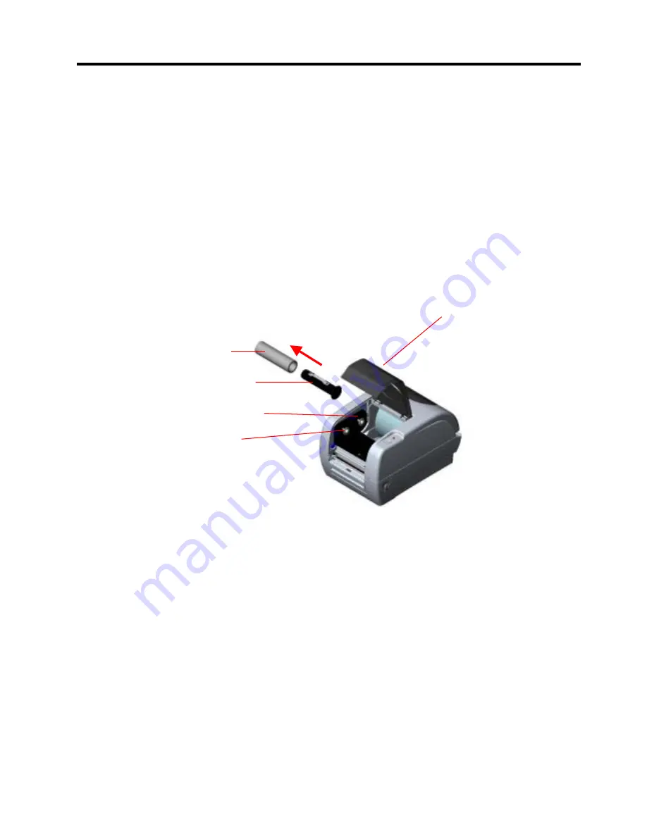
1.  Push down on the ribbon access cover to unlock and open the cover  


2.  Place a paper core on a ribbon rewind spindle. 


3. 

Mount the ribbon rewind paper core on the front hubs.


4.  Install a ribbon on the ribbon supply spindle. 


5. Mount 

the

 ribbon 

supply spindle on the rear hubs

.


6.  Attach the ribbon leader to the ribbon rewind paper core. 


7.  Rotate the ribbon rewind paper core until the ribbon leader is 

thoroughly, firmly encompassed by the black section of the ribbon. 


8. 

Close the ribbon access cover.


Ribbon Spindle  

Front Hub 

Paper Core 

Ribbon Access Cover 

Back Hub 


E2- 9 

Summary of Contents for B-SV4T-GS10-QM

Page 1: ...i TOSHIBA TEC Europe Label Printer B SV4T GS10 QM Owner s Manual Mode d emploi Bedienungsanleitung Manual de instrucciones Gebruikershandleiding Manuale Utente Manual do Utilizador Owner s manual ...

Page 2: ...armful interference to radio communications However there is no guarantee that interference will not occur in a particular installation If this equipment does cause harmful interference to radio or television reception which can be determined by turning the equipment off and on the user is encouraged to try to correct the interference by one or more of the following measures Reorient or relocate t...

Page 3: ...ck Do not plug in or unplug the power cord plug with wet hands as this may cause electric shock If the machines share the same outlet with any other electrical appliances that consume large amounts of power the voltage will fluctuate widely each time these appliances operate Be sure to provide an exclusive outlet for the machine as this may cause fire or electric shock Do not place metal objects o...

Page 4: ...sunlight high temperatures high humidity dust or gas Ensure the printer is operated on a level surface Any data stored in the memory of the printer could be lost during a printer fault Try to avoid using this equipment on the same power supply as high voltage equipment or equipment likely to cause mains interference Unplug the machine whenever you are working inside it or cleaning it Keep your wor...

Page 5: ...2 8 1 Media Sensor Calibration E2 10 2 8 2 Self Print Test and Dump Mode E2 10 3 MAINTENANCE E3 1 3 1 Cleaning E3 1 3 1 1 Print Head E3 1 3 1 2 Platen Sensors E3 2 3 1 3 Cover E3 2 3 2 Care Handling of the Media E3 3 4 TROUBLESHOOTING E4 1 4 1 Troubleshooting Guide E4 1 4 2 Removing Jammed Media E4 1 APPENDIX 1 SPECIFICATIONS EA1 1 A1 1 Printer EA1 1 A1 2 Options EA1 2 A1 3 Media EA1 2 A1 3 1 Medi...

Page 6: ...ble easy media loading and use of a wide range of media All frequently used bar code formats are available in this printer Fonts and bar codes can be printed in any rotation This printer provides a choice of six different type faces of alphanumeric font and outline font printing capability This is the most cost effective and high performance printer in this class 1 3 Unpacking Unpack the printer a...

Page 7: ... ASTA Canada CSA Japan METI UK BSI Denmark DEMKO Netherlands KEMA U S A UL Finland FEI Norway NEMKO France UTE Spain AEE Power Cord Instruction 1 For use with 100 125 Vac mains power supply please select a power cord rated 125V 7A or 10A 2 For use with 200 240 Vac mains power supply Please select a power cord rated Min 250V 2 5A or 5A 3 Please select a power cord with the length of 1 8m to 3m Coun...

Page 8: ...ced in this section are used in the following chapters 213 mm W x 314 mm L x 188 mm H Cover Open Lever Indicator Lamp Feed PAUSE Button Top Cover Ribbon Access Cover Label Roll Capacity View Window 1 2 3 4 5 6 1 USB Interface Connector 2 Parallel Interface Connector Centronics 3 Serial Interface Connector RS 232C 4 Power Jack 5 Power Switch 6 Rear Media Guide ...

Page 9: ...ps printing after completing the current label The printer resumes printing when this button is pressed again Color Illuminates when Flashes when RED A print error such as a memory error syntax error etc The top cover is opened There is no label GREEN The printer is on line and ready to print The button is pressed as a PAUSE function The printer is downloading files Media Guide Platen Media Sensor...

Page 10: ...ith the cover open Be careful not to allow fingers or articles of clothing to get caught into any of the moving parts of the printer Make sure to turn off the printer power and to remove the power adapter connector from the printer whenever working on the inside of the printer or when cleaning the printer For best results and longer printer life use only TOSHIBA TEC recommended media Store the med...

Page 11: ...ion 2 7 NOTE Use of a Windows Driver will allow issuing media on the printer from a Windows application The printer can also be controlled with its own programming commands For details please contact your TOSHIBA TEC reseller 8 Adjust the position of the Feed Gap Sensor or Black Mark Sensor to match the media being used Refer to Section 2 8 9 Turn the Power ON Refer to Section 2 3 10 Install the P...

Page 12: ... These are A serial cable connection between the printer s RS 232C serial connector and one of your host computer s COM ports A parallel cable connection between the printer s standard parallel connector and your host computer s parallel port LPT A USB cable connection between the printer s USB interface connector and one of your host computer s USB port The diagram below shows all the possible ca...

Page 13: ...wer Adapter connector into the Power Jack on the rear of the printer 4 Plug the other end of the Power Cord into a grounded outlet as shown in the figure below Power Adapter Power Cord Power Adapter Connector Power Jack NOTES 1 Since the power cord is not enclosed in this printer please purchase a proper one after referring to page 1 2 2 The EA10953 AC adapter should be exclusively used for the B ...

Page 14: ...ia Holder by sliding it onto the Media Shaft Make sure that the media roll is positioned at the centre of the Media Shaft 7 Insert the Media Holder Ass y into the slots of the printer WARNING 1 Do not touch any moving parts To reduce the risk of fingers jewellery clothing etc being drawn into the moving parts be sure to load the media once the printer has stopped moving completely 2 To avoid injur...

Page 15: ...rse side of the media There are three issue modes available on this printer Batch mode In the batch mode the media is continuously printed and fed until the number of media specified in the issue command has been printed Media Guide CAUTION To separate the printed media from the media roll in batch mode be sure to tear off the media at the Media Outlet or cut the media past the Tear Off Bar If you...

Page 16: ...bel Backing Paper NOTE When the media is correctly set the backing paper is supposed to be pinched by the Platen and the Strip Feed Roller as shown below 1 When attaching or removing the cutter cover be sure to turn off the power Otherwise you may be injured 2 The cutter is sharp so care must be taken not to injure yourself when handling the cutter WARNING CAUTION 1 Be sure to cut the backing pape...

Page 17: ...in the External Media Roll Hanger External Media Roll Hanger Option 2 Load a media roll onto the printer s Media Holder Ass y and place it into the cuts of the External Media Roll Hanger 3 Pull the media forward and insert the leading edge into the printer so that it passes between the Rear Media Guides Rear Media Guides Paper Guide Media Holder Ass y 4 Manually move the Rear Media Guides so that ...

Page 18: ...ver are closed when powering the printer up 1 Push down on the ribbon access cover to unlock and open the cover 2 Place a paper core on a ribbon rewind spindle 3 Mount the ribbon rewind paper core on the front hubs 4 Install a ribbon on the ribbon supply spindle 5 Mount the ribbon supply spindle on the rear hubs 6 Attach the ribbon leader to the ribbon rewind paper core 7 Rotate the ribbon rewind ...

Page 19: ... unlit Reflective Black Mark Sensor is selected The Indicator Lamp illuminates in green About 3 seconds 2 Turn off the printer power and install blank media without pre printing on the printer 3 To calibrate the Black Mark Sensor align the sensor position with the black marks on the media Refer to Section 2 6 4 Press the FEED PAUSE Button while turning on the printer The Indicator Lamp will be ill...

Page 20: ...fine adjustment value CUT POSITION ADJUST XX Xmm Cut position fine adjustment value BACKFEED ADJUST XX Xmm Back feed amount fine adjustment value PARAMETER PC 850 0 Character code selection and Font 0 selection 9600 8 1 NONE 0 Baud rate Data length Stop bit length Parity and Transmission control of RS 232C ON AUTO FEED B0 Forward feed wait function Control code Feed key function and Euro code X CO...

Page 21: ...o turn OFF the power before performing maintenance Failure to do this may cause an electric shock 2 To avoid injury be careful not to pinch your fingers while opening or closing the cover and print head block 3 Be careful when handling the print head as it becomes very hot immediately after printing Allow it to cool before performing any maintenance 4 Do not pour water directly onto the printer CA...

Page 22: ...st or paper particles from the Media Sensor and Cover Open Sensor using an air blower Wipe the Cover with a dry soft cloth Wipe off dirt with a soft cloth slightly moistened with water CAUTION Do not use any volatile solvents including thinner and benzene as this may cause discoloration or distortion of the cover Platen Media Sensor Cover Open Sensor ...

Page 23: ...h humidity dust or gas The thermal paper used for direct thermal printing must not have specifications which exceed Ca2 K Na 800 ppm and Cl 600 ppm Some ink used on pre printed media may contain ingredients which shorten the print head s product life Do not use labels pre printed with ink which contain hard substances such as carbonic calcium CaCO3 and kaolin Al2O3 2SiO2 2H2O For further informati...

Page 24: ... the print start position Retry the Media Sensor calibration 3 A paper jam occurred 4 A cutter jam occurred After removing causes of the problems press the FEED PAUSE Button to return to Online state Poor print quality 1 The Top Cover is not closed completely Close the Top Cover completely 2 Clean the Print Head 3 The media being used is not with in specification Use TOSHIBA TEC recommended media ...

Page 25: ... supply 5 C to 40 C 40 F to 104 F 40 C to 60 C 25 to 85 RH no condensation 10 to 90 RH no condensation Free air environment 203 dpi Thermal transfer and Direct thermal Batch Strip Cut 50 8 mm sec 2 sec 76 2 mm sec 3 sec 101 6 mm sec 4 sec 127 mm sec 5 sec 50 8 mm sec 2 sec 76 2 mm sec 3 sec 25 4 mm 1 0 to 112 mm 4 4 108 0 mm 4 3 213 0 mm 314 0 mm 188 0 mm 8 4 12 4 7 4 2 8 kg 6 2 lb Excluding Media...

Page 26: ...ess paper printing kit B SV904 LP QM This kit consists of a platen and a sheet which prevent the linerless paper from sticking to the printer inside LAN adapter B SV704 LAN QQ For AC100 to 120V B SV704 LAN QP For AC200 to 240V This option enables the printer to be used in a LAN network A1 3 Media Please make sure that the media to be used is approved by TOSHIBA TEC The warranties do not apply to p...

Page 27: ...e Transmissive Sensor detects a gap between labels as illustrated below A1 3 3 Detection Area of the Reflective Sensor The Reflective Sensor is movable within the full range of the media width The reflection factor of the Black Mark must be 10 or lower with a waveform length of 950 nm The Reflective Sensor should be aligned with the centre of the Black Mark NOTES 1 To ensure print quality and prin...

Page 28: ...ape 2 mm 112 0 mm Max media width 108 0 mm 0 2mm Head Effective Print Range Out of print range Out of print range 2 mm NOTES 1 Be sure not to print on the 1 5 mm wide area from the media edges shaded area in the above figure 2 The centre of media should be positioned at the centre of the print head 3 Print quality is not guaranteed within 3 mm from the print head stop position including 1 mm slow ...

Page 29: ...itted with metal or metallized connector housings Keep as short as possible Should not be bundled tightly with power cords Should not be tied to power line conduits RS 232C Cable description The serial data cable used to connect the printer to a host computer should be one of the following two types 9 pin or 25 pin connector Connector to the Host Computer Connector to Printer NOTE Use an RS 232C c...

Page 30: ...he print start position of the label Font A complete set of alphanumeric characters in one style of type E g Helvetica Courier Times Gap Distance from the bottom of one label to the top of the next label IPS Inch per second A unit used to express print speed Label A type of media with adhesive backing supplied on a backing paper Media Material on which images are printed by the printer Label tag p...

Reviews: