background image

6


Specifications


Toshiba


B

FV4T


Owner’s


Manual


‐ 

53

 ‐ 

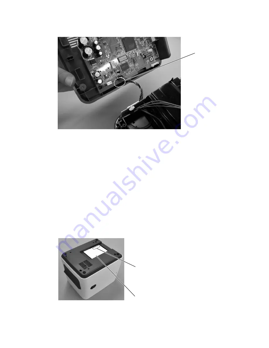
7) Connect the harness connector to the connector “J15” (black) on the main board. 


8) Return the 6 connectors to the original positions, which were removed in Step 3. 


9) Fix the Bottom Cover by securing the 4 screws which were removed in Step 2. 

Note: When fitting the Bottom Cover, prevent the harness from being trapped between the 

covers. 


10) Peel off the backing sheet of the RF Certification Label and attach it to the position as 

shown below. 


Connector


“J15”


(black)


RF


Certification


Label


Rating


Label


Summary of Contents for B-FV4T-GS12-QM-R

Page 1: ...B FV4T SERIES Printer Owner s Manual B FV4T GS12 QM R B FV4T GS14 QM R B FV4T TS12 QM R B FV4T TS14 QM R ...

Page 2: ...n If this equipment does cause harmful interference to radio or television reception which can be determined by turning the equipment off and on the user is encouraged to try to correct the interference by the following measures Reorient or relocate the receiving antenna Increase the separation between the equipment and the receiver Connect the equipment into a different outlet on a different circ...

Page 3: ...very of the accompanying product including hardware and software be liable for any damages whatsoever including without limitation damages for loss of business profits business interruption loss of business information or other pecuniary loss arising out of the use of or the results of use of or inability to use such product even if Toshiba has been advised of the possibility of such damages Cauti...

Page 4: ...antennas Europe EU Declaration of Conformity Hereby TOSHIBA TEC declares that B FV4D series are in compliance with the essential requirements and other relevant provisions of Directive 1999 5 EC USA Federal Communications Commission FCC NOTE This equipment has been tested and found to comply with the limits for a Class A digital device pursuant to part 15 of the FCC Rules These limits are designed...

Page 5: ...is device could void the user s authority to operate the equipment RF EXPOSURE WARNING This equipment must be installed and operated in accordance with provided instructions and the antenna s used for this transmitter must be installed to provide a separation distance of at least 20 cm from all persons and must not be co located or operating in conjunction with any other antenna or transmitter End...

Page 6: ...ld be used in such a manner such that the potential for human contact during normal operation is minimized This device has been evaluated for and shown compliant with the IC Specific Absorption Rate SAR limits when operated in portable exposure conditions Informations concernant l exposition aux fréquences radio RF La puissance de sortie émise par l appareil de sans fil est inférieure à la limite ...

Page 7: ... devices simultaneously you may occasionally experience a less than optimal network performance or even lose your network connection If you should experience any such problem immediately turn off your Bluetooth device Keep away from a microwave Communication performance may deteriorate or a communication error may occur due to the radio emitted from a microwave Do not use the product on a metal ta...

Page 8: ...rinter 10 2 2 2 Turn Off the Printer 11 2 3 Loading Media 11 2 3 1 Preparing Media 11 2 3 2 Placing Media Roll 12 2 3 3 Testing Media Feed 16 2 3 4 Media Types 17 2 4 Loading Ribbon 19 2 4 1 Preparing Ribbon 19 2 4 2 Placing Ribbon Roll 20 3 Printer Operation 24 3 1 Media Sensor Calibration 24 3 2 Self Test and Dump Mode 25 3 2 1 Self Test 25 3 2 2 Dump Mode 27 3 3 Restore Your Printer to Factory ...

Page 9: ... 1 Printer Problems 35 5 2 Media Problems 35 5 3 Ribbon Problems 36 5 4 Other Problems 37 6 Specifications 39 6 1 Printer 39 6 2 Media and Ribbon 40 6 3 Bar Code 41 6 4 Electrical and Operating Environment 43 6 5 Physical Dimension 43 6 6 Interfaces 44 6 6 1 USB 44 6 6 2 Ethernet 45 6 6 3 RS 232C 46 6 6 4 Centronics 46 ...

Page 10: ...peration One button design for easy control High Print Resolution 203 dpi for GS models 300 dpi for TS models Fast Print Speed Max 6 inches sec for GS models max 4 inches sec for TS models High Capacity 5 inch diameter media roll and the 300 meter ribbon allow you to print labels without frequently replacing the media and ribbon External Memory The extra USB port allows you to use a USB flash driv...

Page 11: ...eive the printer open the package immediately and inspect for shipping damage If you discover any damage contact the shipping company and file a claim Toshiba is not responsible for any damage incurred during shipping Save all package materials for the shipping company to inspect Note If any item is missing please contact your local dealer ...

Page 12: ...1 Introduction Toshiba B FV4T Owner s Manual 3 1 3 Understanding Your Printer 1 3 1 Front View LED 2 LED 1 FEED Button ...

Page 13: ...1 Introduction Toshiba B FV4T Owner s Manual 4 1 3 2 Rear View Optional Interfaces ...

Page 14: ...1 Introduction Toshiba B FV4T Owner s Manual 5 1 3 3 Interior View I ...

Page 15: ...1 Introduction Toshiba B FV4T Owner s Manual 6 1 3 4 Interior View II ...

Page 16: ...reen Off In a pause state Green Green The printer is writing data to the flash or USB memory Green Green The USB memory is being initialized The process takes about 15 seconds Orange Green Paper jam Orange Orange Ribbon end or ribbon error for thermal transfer models Orange Red The media is out when the print data is sent to the printer Orange Red Paper end Red Green Communication error RS 232C Re...

Page 17: ...hey turn to green shortly and then turn to other colors 4 When status lights show the color combination you need release the FEED button immediately 5 Press the FEED button to run the command The following table is the command list of the system mode LED 1 LED 2 Command Green Red Transmissive Sensor Calibration Section 3 1 Green Orange Reflective Sensor Calibration Section 3 1 Red Red Restore the ...

Page 18: ... to the OFF position 2 Insert the power supply s connector into the printer power jack 3 Insert the AC power cord into the power supply 4 Plug the other end of the AC power cord into the wall socket Warning Do not plug the AC power cord with wet hands or operate the printer and the power supply in an area where they may get wet Serious injury may result from these actions ...

Page 19: ...inter 2 2 1 Turn On the Printer 1 To turn on the printer turn on the Power Switch as below The I is the ON position 2 Both status lights will light up solid orange for a few seconds and then LED 2 goes out while LED 1 turns to solid green Note If you connect the printer to the network or insert a USB drive before turning on the printer it will take longer for the printer to enter the online mode L...

Page 20: ... Warning Do not turn off the printer during data transmission 2 3 Loading Media There are various types and sizes for the media roll Load the applicable media to satisfy your need 2 3 1 Preparing Media The inside wound and outside wound media roll can be loaded into the printer the same way In case the media roll is dirty during shipping handling or storage remove the outside length of the media I...

Page 21: ...2 Getting Started Toshiba B FV4T Owner s Manual 12 between the printhead and platen roller Inside Wound Outside Wound 2 3 2 Placing Media Roll 1 Open the top cover of the printer ...

Page 22: ...witch lock on the Media Roll Holders to slide them outward and place the media roll between the holders Adjust the media roll so its print side is facing up and make sure it is clamped tightly by the holders 3 Push the Module Release Latch to open the printer module ...

Page 23: ...2 Getting Started Toshiba B FV4T Owner s Manual 14 4 Press the Lock button on the Media Guides to slide them outward 5 Pull the media until it reaches out of the printer ...

Page 24: ...g Started Toshiba B FV4T Owner s Manual 15 6 Put the media under the Media Shaft and center it between the Media Guides 7 Close the printer module and press down firmly at its both sides until you hear a click ...

Page 25: ...4T Owner s Manual 16 2 3 3 Testing Media Feed If you need to test the media feed do this 1 Turn on the printer and press the FEED button to feed a label out of the printer 2 To tear the media pull the media gap against the Tear Bar ...

Page 26: ...edia The following table provides details about them Media Type Looks Like Description Non Continuous Media Non continuous media is the typical media for bar code printing Labels and tags are made of various materials such as paper fabric or cardstock and are separated by gaps holes notches or black marks Many labels are self adhesive with liners while some are linerless ...

Page 27: ... the media A cutter may be used for splitting labels Mostly it is used for direct thermal printing Fanfold Media Fanfold media is in continuous form but it can be used as non continuous media because its labels are separated by folds Some fanfold media also has black marks or liners Note If you are using thermal transfer mode please continue to Section 2 4 Loading Ribbon ...

Page 28: ...ch other to get the proper print quality The ribbon needs to be wider than or equal to the media to protect the printhead from wear 2 4 1 Preparing Ribbon Remove the wrapping and the protective film of the ribbon You will find two pairs of ribbon cores in the printer package One of them is for 0 5 inch inner diameter ribbon and the other is for 1 inch Install the applicable pair into the ribbon su...

Page 29: ...2 Getting Started Toshiba B FV4T Owner s Manual 20 2 4 2 Placing Ribbon Roll 1 Open the top cover of the printer 2 Push the Module Release Latch to open the printer module ...

Page 30: ...l 21 3 Lift the printer module to reveal the Supply Wheel 4 Do the following to install both rolls To load the supply roll align the notches on the left side and press the roll to the supply hub and then press the right side of the roll to the hole ...

Page 31: ...er s Manual 22 To load the take up roll align the notches on the left side and press the roll to the take up hub and then press the right side of the roll to the hole 5 Pull the ribbon from the supply roll and tape it on the take up roll ...

Page 32: ...press down firmly at its both sides until you hear a click 7 Rotate the Take Up Wheel to straighten the ribbon and reduce its wrinkles Note For the supply hub the ribbon wind direction can be coated side in CSI or coated side out CSO for the take up hub the wind direction must be CSO ...

Page 33: ...er module is closed and the printer s power switch is set to the OFF position 2 Press and hold the FEED button and turn on the printer 3 Both status lights will light up solid orange for a few seconds Next they turn to green shortly and then turn to other colors Do one of the following to select the sensor If you want to calibrate the transmissive sensor when LED 1 turns to green and LED 2 turns t...

Page 34: ...ngs of the printer 3 2 1 Self Test 1 Turn off the printer 2 Press and hold the FEED button and turn on the printer 3 Both status lights will light up solid orange for a few seconds Next they turn to green shortly and then turn to other colors When LED 1 turns to orange and LED 2 turns to green release the FEED button 4 Press the FEED button The printer will print a configuration label ...

Page 35: ...3 Printer Operations Toshiba B FV4T Owner s Manual 26 Your configuration label should look like this ...

Page 36: ...reset your printer 1 Turn off the printer 2 Press and hold the FEED button and turn on the printer 3 Both status lights will light up solid orange for a few seconds Next they turn to green shortly and then turn to other colors When both lights turn to red release the FEED button immediately 4 Press and hold the FEED button for 3 seconds and release it Both status lights will blink red three times ...

Page 37: ...two media sensor types transmissive and reflective They are used for detecting specific media types 3 4 1 Transmissive Sensor The transmissive sensor is fixed and placed near the center of the media path It is used for detecting gaps across the entire width of the label Single Column ...

Page 38: ...ive Sensor The reflective sensor is movable within the entire width of the media It detects gaps notches and black marks not located at the center of the media Multi Columns Notch Black Mark Flip the media so the black mark side is facing down to align with the sensor ...

Page 39: ...rongly recommend that you clean the printhead when you load a new media roll If the printer is operated in critical environment or the print quality declines you need to clean the printhead more frequently Keep in mind these things before you clean Keep the water away in case of corrosion on heating elements If you just finish printing wait until the printhead cools down Do not touch the printhead...

Page 40: ...ed or made illegible under every circumstance 4 1 2 Media Housing Use a soft cloth to clean the dust dirt or debris built up on the Media Roll Holders Media Guides and media path 1 Moisten a soft cloth with ethyl alcohol 2 Wipe the Media Roll Holders to clean dust 3 Wipe the Media Guides to clean dust and dirt 4 Wipe the media path to clean paper debris ...

Page 41: ... 4 1 3 Sensor Media sensors may not be able to detect the media correctly if it becomes dirty 1 Moisten a soft cloth or a cotton swab with absolute ethyl alcohol 2 Gently brush sensors to remove the dust away 3 Use a dry cloth to clean the residue ...

Page 42: ...ller is also important for print quality Dirty platen roller may damage the printhead Clean the platen roller right away if the adhesive dirt or dust accumulates on it 1 Moisten a soft cloth with absolute ethyl alcohol 2 Gently wipe the platen roller to remove the dust and adhesive ...

Page 43: ...k of the current time You can check the RTC battery charge from the status lights If the RTC battery is low or out you need to replace it with a new one Take the following steps to replace your RTC battery 1 Turn on the printer 2 Locate the battery on the main board 3 Remove the old coin battery and install a new one 4 Turn off the printer Warning Risk of explosion if battery is replaced by an inc...

Page 44: ...rical devices Disconnect the printer from the wall socket and connect it again The printer does not feed the media out The media is not loaded correctly See Section 2 3 Loading Media to reload the media If there is a paper jam clear it I accidentally press the feed button while the printer module is opened Close the printer module and press the FEED button 5 2 Media Problems The media is out Load ...

Page 45: ...the ribbon The print data might not be sent successfully Make sure the interface is set correctly in the printer driver and send the print data again The print quality is poor The printhead is dirty Clean the printhead The platen roller is dirty Clean the platen roller Adjust the print darkness or lower the print speed The media is incompatible for the ribbon Use the compatible media instead The m...

Page 46: ...ump mode If the print darkness is very high adjust it in printer preference or reset your printer see Section 3 3 Restore Your Printer to Factory Settings The ribbon is wrinkled 1 Make sure the ribbon is loaded correctly 2 Rotate the Take Up Wheel to straighten the ribbon 5 4 Other Problems There are broken lines in the printed label The ribbon is wrinkled Adjust or reload the ribbon Or print a fe...

Page 47: ...in position and tighten it The cutter blade is not sharp anymore Replace your cutter with a new one The printhead temperature is extremely high The printhead temperature is controlled by the printer If it is extremely high the printer will stop printing automatically until the printhead is cool down After that the printer will resume printing automatically if there is any unfinished print job The ...

Page 48: ...de Print Darkness Darkness level 10 10 Default 0 Max Printable Area Length 999 mm x Width 108 mm Length 999 mm x Width 105 7 mm Non Printable Area Pitch Direction Top 1 mm Bottom 1 mm excluding liner Width Direction Left 1 mm Right 1 mm excluding liner Print Ratio Average print ratio within 15 or less whole print layout area Full width with 1mm pitch is required Interface USB Type A and Type B Eth...

Page 49: ... 22 4 115 mm including liner 25 4 118 mm Cut Mode Length 19 4 993 mm including liner 25 4 999 mm Width 22 4 115 mm including liner 25 4 118 mm Max Roll Diameter Size 127 mm 5 inches Max Roll Diameter Size for External Media Stand 216 mm 8 5 inches Media Type Thermal Transfer Label Thermal Transfer Tag Direct Thermal Label Direct Thermal Tag Roll Paper Inside Wound or Outside Wound Fanfold Paper Ri...

Page 50: ... EAN128 CODABAR NW 7 ITF Industrial 2of5 MSI UPC add on code POSTNET GS1 DataBar Omnidirectional GS1 DataBar Truncated GS1 DataBar Stacked GS1 DataBar Stacked Omnidirectional GS1 DataBar Limited GS1 DataBar Expanded GS1 DataBar Expanded Stacked Two Dimensional Bar Code QR Code PDF417 MicroPDF DataMatrix ECC200 FNC1 supported MaxiCode QR Code PDF417 including MicroPDF DataMatrix ECC200 GS1 DataMatr...

Page 51: ...taBar Truncated Composite CC A CC B GS1 DataBar Stacked Composite CC A CC B GS1 DataBar Expanded Stacked Composite CC A CC B GS1 DataBar Expanded Composite CC A CC B GS1 DataBar Stacked Omnidirectional Composite CC A CC B GS1 DataBar Limited Composite CC A CC B GS1 128 Composite CC A CC B CC C ...

Page 52: ... 10 full range Frequency 50 60 Hz 5 Power Consumption 90 W Temperature Operating 5 40 C Storage 40 60 C Humidity Operating 25 85 RH non condensing Storage 10 90 RH non condensing 6 5 Physical Dimension Dimension Size and Weight Size W 221 mm x D 279 3 mm x H 182 8 mm Weight 2 45 kg excluding media and accessories ...

Page 53: ... printer 6 6 1 USB There are two common USB connectors Typically type A is found on hosts and hubs type B is found on devices and hubs The figure below shows their pinouts Type A Type B Pin Signal Description 1 VBUS 5V 2 D Differential data signaling pair 3 D Differential data signaling pair 4 Ground Ground ...

Page 54: ...6 2 Ethernet The Ethernet uses RJ 45 cable which is 8P8C 8 Position 8 Contact The figure below shows its pinout 1 2 3 4 5 6 7 8 Pin Signal 1 Transmit 2 Transmit 3 Receive 4 Reserved 5 Reserved 6 Receive 7 Reserved 8 Reserved ...

Page 55: ...in 9 is reserved for KDU Do not connect it if you are using a computer as the host Host DB9 Printer DB9 Signal Description Pin Pin Description Signal RxD Receive 2 3 Transmit TxD TxD Transmit 3 2 Receive RxD DTR Data Terminal Ready 4 1 Data Set Ready DSR GND Ground 5 5 Ground GND DSR Data Set Ready 6 6 Data Terminal Ready DTR RTS Request to Send 7 8 Clear to Send CTS CTS Clear to Send 8 7 Request ...

Page 56: ... Printer BUSY 2 To Printer Data 1 12 From Printer PE 3 To Printer Data 2 13 From Printer 5V 4 To Printer Data 3 14 15 NC 5 To Printer Data 4 16 17 Ground GND 6 To Printer Data 5 18 NC 7 To Printer Data 6 19 30 Ground GND 8 To Printer Data 7 31 NC 9 To Printer Data 8 32 From Printer FAULT 10 From Printer ACK 33 36 NC ...

Page 57: ...NING 1 Carefully read and follow all the instructions in this manual Failure to do so could create safety hazards such as fire or electric shocks Instructions in this manual must be followed when installing option kits or adding cables to avoid system failures and to insure correct performance and operation Failure to follow the manual s instructions or any unauthorized modifications substitution ...

Page 58: ...B FV700 BLTH QM R 49 Bluetooth Interface 1 pc M 3 P Tite Screw 2 pcs Installation Manual 1 copy RF Certification Label ...

Page 59: ... plug from the AC outlet and disconnect the AC adapter from the printer 2 Place the printer on the soft cloth to prevent scratching the surface of the printer and remove the 4 screws provided at the Bottom Cover 3 Remove the Bottom Cover by removing the 6 connectors from the main board Connectors to be detached Bottom Cover ...

Page 60: ...Remove the Printer Cover 5 Secure the Bluetooth Interface with the 2 screws provided M 3 P Tite screws Note When securing the interface prevent the two harnesses from being trapped between the interface board and the printer frame Printer Cover Harnesses ...

Page 61: ...6 Specifications Toshiba B FV4T Owner s Manual 52 6 Attach the Printer Cover Note When fitting the Printer Cover prevent the harness from being trapped between the covers Printer Cover ...

Page 62: ... positions which were removed in Step 3 9 Fix the Bottom Cover by securing the 4 screws which were removed in Step 2 Note When fitting the Bottom Cover prevent the harness from being trapped between the covers 10 Peel off the backing sheet of the RF Certification Label and attach it to the position as shown below Connector J15 black RF Certification Label Rating Label ...

Page 63: ...d on the rating label when the RF Certification Label is attached to the upper right corner 11 Close the Top Cover The installation is now completed PRINTED IN TAIWAN R141023P5200 TTEC EO2 38103 Feb 2015 2015 TOSHIBA TEC CORPORATION All Rights Reserved 1 11 1 Osaki Shinagawa ku Tokyo 141 8562 JAPAN ...

Reviews: