background image

1. PRODUCT OVERVIEW 

ENGLISH VERSION EO1-33114 

1.5 Appearance


1.4 Appearance 


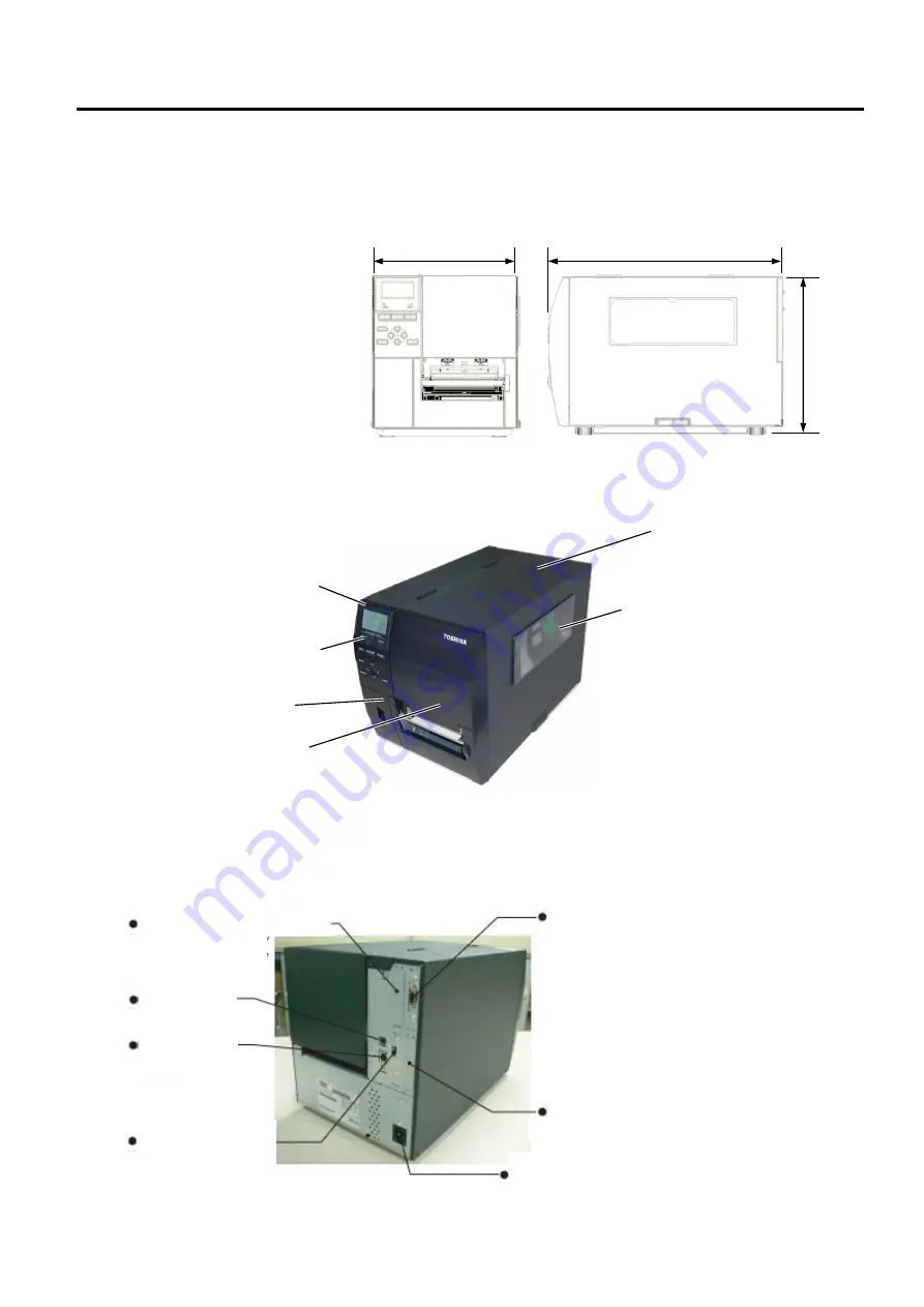
1.4.1 Dimensions 


1.4.2 Front 

View 


1.4.3 Rear 

View


The names of the parts or units introduced in this section are used in the 
following chapters. 


278 (10.9) 

460 (18.1) 


Dimensions in mm (inches) 

310 

(12.2) 

Top Cover 

Media Outlet 

Supply Window 

LCD Message Display 

Operation Panel 

Serial Port


USB Port


Parallel Port (Option)


LAN Port


USB Host Port 

Option


Expansion I/O (Option)


Power inlet


Power switch 

Summary of Contents for B-EX4T3

Page 1: ...Toshiba Barcode Printer B EX4T3 SERIES Owner s Manual ...

Page 2: ... Regulation ...

Page 3: ...ing the Ribbon 11 2 4 Connecting the Cables to Your Printer 12 2 5 Turning the Printer ON OFF 13 2 5 1 Turning ON the Printer 13 2 5 2 Turning OFF the Printer 13 3 MAINTENANCE 14 3 1 Cleaning 14 3 1 1 Print Head Platen Sensors 14 3 1 2 Covers and Panels 15 3 1 3 Optional Cutter Module 16 4 PRINTER SPECIFICATIONS 17 5 SUPPLY SPECIFICATIONS 27 5 1 Media 27 5 1 1 Media Type 27 5 1 2 Detection Area of...

Page 4: ...ribbon Various types of media can be used as the media sensors can be moved from the center to the left edge of the media Web based functions such as remote maintenance and other advanced network features are available Superior hardware including the specially developed 23 6 dots mm 600 dots inch thermal print head which will allow very clear print at a printing speed of 2 3 4 5 or 6 inches sec Be...

Page 5: ... names of the parts or units introduced in this section are used in the following chapters 278 10 9 460 18 1 Dimensions in mm inches 310 12 2 Top Cover Media Outlet Supply Window LCD Message Display Operation Panel Serial Port USB Port Parallel Port Option LAN Port USB Host Port Option Expansion I O Option Power inlet Power switch ...

Page 6: ...terior Please see Section 3 for further information about the Operation Panel LCD ERROR LED PAUSE RESTART UP RIGHT ENTER DOWN CANCEL MODE LEFT FEED ONLINE LED Damper Ribbon Shaft Supply Shaft Locking Ring Supply Holder Ribbon shaft holder Head Lever Ribbon Stopper Print head Warning High temp ...

Page 7: ...or to take up labels and backing paper together when using the rewind guide plate To support peel off minimum 3mm length label Expansion I O interface card B EX700 IO QM R Installing this card in the printer allows connection to an external device with the exclusive interface Parallel interface card B EX700 CEN QM R Installing this card provides a Centronics interface port RTC USB host interface c...

Page 8: ... Loading the ribbon Connecting to a host computer Make a print test from your operating environment and check the print result Print test 2 1 Installation 2 2 Connecting the Power Cord 2 3 1 Loading the Media 2 3 1 Loading the Media 2 3 2 Loading the Ribbon 2 4 Connecting the Cables to Your Printer 2 6 Printer Setting 2 8 Print Test Automatic threshold setting Manual threshold setting If necessary...

Page 9: ...ional cutter mechanism Make sure to turn off the power and remove the power cord whenever working inside the printer For example when changing the ribbon loading the media or cleaning the printer For best results and longer printer life use only Toshiba Tec recommended media and ribbons Store the media and ribbons in accordance with their specifications This printer mechanism contains high voltage...

Page 10: ... 2 Plug the other end of the Power Cord into a grounded outlet as shown in the figure below Example of US Type Example of EU Type CAUTION 1 Make sure that the printer Power Switch is turned to the OFF position before connecting the Power Cord to prevent possible electric shock or damage to the printer 2 Connect the Power Cord to a supply outlet with a properly grounded earthed connection Power Cor...

Page 11: ...g or closing the cover WARNING CAUTION 1 Be careful not to touch the Print Head Elements when lifting the Print Head Block This may cause missing dots due to static electricity or other print quality problems 2 When loading or replacing the media or ribbon be careful not to damage the print head with hard objects like watches or rings Since the print head element can be easily damaged by shock ple...

Page 12: ...y Holder from the Supply Shaft 5 Put the media on the Supply Shaft 6 Pass the media around the Guide Shaft then pull the media towards the front of the printer Locking Ring Supply Holder Supply Shaft NOTES 1 When the Head Lever is turned to FREE position the Print Head can be raised 2 To enable printing the Head Lever must be set to the LABEL2 position This ensures that the Print Head is closed Ho...

Page 13: ...older 8 Place the media between the Media Guides and adjust them to the media width Once in the correct position tighten the Locking Screw 9 Check that the media s path through the printer is straight The media should be centered under the Print Head NOTE Do not over tighten the Locking Ring of the Supply Holder Media Guide Supply Holder Media Guide Print Head Locking Screw Media Guide Shaft Media...

Page 14: ...d Gap Sensor Setting the Black Mark Sensor position 1 Pull about 500 mm of media out of the front of the printer turn the media back on itself and feed it under the Print Head past the sensor so that the black mark can be seen from above 2 Manually move the Media Sensor so that the Black Mark Sensor is in line with the center of the black mark on the media indicates the position of the Black Mark ...

Page 15: ...VERSION EO1 33114 2 3 Loading Supplies 13 2 3 1 Loading the Media Cont 12 Batch mode In the batch mode the media is continuously printed and fed until the number of labels tags specified in the issue command have been printed ...

Page 16: ... module is fitted insert the leading edge of the media into the cutter until it comes out the media outlet of the cutter cover The media is automatically cut CAUTION 1 Be sure to cut the backing paper of the label Cutting labels will cause the glue to stick to the cutter which may affect the cutter quality and shorten the cutter life 2 Cutting tag paper whose thickness exceeds the specified value ...

Page 17: ...it 2 Remove enough labels from the leading edge of the media to leave 200mm of backing paper free 3 Insert the leading edge of the backing paper under the backing paper feed roller 4 Close the peel off unit until it clicks 5 Manually move the peel off sensor so that it is in line with the center of labels coming out of the media outlet Basically align the sensor with the center of the media outlet...

Page 18: ...TER SETUP ENGLISH VERSION EO1 33114 2 3 Loading Supplies 16 6 Set the ribbon shaft holder plate and turn the head lever to LABEL2 position 7 Close the top cover Top cover Head lever Ribbon shaft holder plate ...

Page 19: ... selection switch to STANDARD PEEL OFF position 2 Fit the take up clip so that the longer side of the clip is fitted into the shallow groove in the take up spool 3 Insert the take up clip fully 4 Backing paper can be wound directly onto the take up spool or a paper core fitted on the take up spool When winding backing paper directly onto the Take up spool detach the spring plate from the take up s...

Page 20: ...ow Ribbon path Ribbon Shaft Ribbon Take up Roll Print Head Block Ribbon Stopper Ribbon Shaft NOTES 1 When attaching the ribbon stoppers make sure that the pinchers face into the printer 2 Be sure to remove any slack in the ribbon before printing Printing with a wrinkled ribbon will reduce the print quality 3 The Ribbon Sensor is mounted on the rear of the Print Head Block to detect a ribbon end Wh...

Page 21: ...d when fitted 4 Lower the Print Head Block and set the Ribbon Shaft Holder Plate aligning its holes with the Ribbon Shafts 5 Take up any slack in the ribbon Wind the leading tape onto the ribbon take up roll until the ink ribbon can be seen from the front of the printer 6 Turn the Head Lever to Label2 position to close the Print Head 7 Close the Top Cover Ribbon Shaft Holder Plate ...

Page 22: ...our host computer These are An Ethernet connection using the printer s standard LAN connector A USB cable connection between the printer s standard USB connector and your host computer s USB port Conforming to USB 2 0 A serial cable connection between the printer s RS 232 serial connector and one of your host computer s COM ports A parallel cable connection between the printer s optional parallel ...

Page 23: ... the printer Power Switch verify that the ON LINE message appears in the LCD Message Display and that the ON LINE LED light is on and is not flashing 2 To turn OFF the printer power press the Power Switch as shown in the diagram below Note that is the power OFF side of the switch CAUTION Use the power switch to turn the printer On Off Plugging or unplugging the Power Cord to turn the printer On Of...

Page 24: ...r the media or ribbon is replaced 1 Turn off the power and unplug the printer 2 Open the Top Cover 3 Turn the Head Lever to the FREE position and then release the Ribbon Shaft Holder Plate 4 Open the Print Head Block 5 Remove the ribbon and media CAUTION When cleaning the print head be careful not to damage the print head with hard objects like watches or rings WARNING 1 Be sure to disconnect the ...

Page 25: ...ck Mark Sensor with a dry soft cloth Wipe the covers and panels with a dry soft cloth or a cloth slightly moistened with a mild detergent solution CAUTION 1 DO NOT POUR WATER directly onto the printer 2 DO NOT APPLY cleaner or detergent directly onto any cover or panel 3 NEVER USE THINNER OR OTHER VOLATILE SOLVENT on the plastic covers 4 DO NOT clean the panel covers or the supply window with alco...

Page 26: ...Head Screws to remove the Cutter Cover 2 Remove the jammed paper 3 Clean the Cutter with a soft cloth slightly moistened with alcohol 4 Attach the Cutter Cover Cutter Unit Plastic Head Screw WARNING 1 Be sure to turn the power off before cleaning the Cutter Module 2 As the cutter blade is sharp care should be taken not to injure yourself while cleaning ...

Page 27: ...During a print job 110W During stand by 15W or less During sleep mode 4 7W Resolution 600 dpi 23 6 dots mm Printing method Thermal transfer Printing speed 50 8 mm sec 2 inches sec 76 2 mm sec 3 inches sec 101 6 mm sec 4 inches sec 127 0 mm sec 5 inches sec 152 4 mm sec 6 inches sec Available media width including backing paper 25 0 mm to 110 mm 0 98 inches to 4 33 inches Effective print width max ...

Page 28: ...ro PDF417 CP Code GS1 Data Matrix AZTEC Code GS1 QR Code Font Bitmap font 21 types Japanese Kanji JIS X0213 4 types Gothic 2 types Mincho Chinese Outline font 8 types Writable character True Type Font Rotations 0 90 180 270 deg Standard interface USB interface Serial interface LAN interface Optional interface Parallel interface B EX700 CEN QM R Expansion I O interface B EX700 IO QM R USB host inte...

Page 29: ...is not approved by Toshiba Tec For information regarding Toshiba Tec approved media please contact a Toshiba Tec authorized service representative 5 1 1 Media Type Two types of media can be loaded for this printer label or tag The table below shows size and shape of the media available for this printer Label Tag paper Cut position Cut position Stop position Stop position Feed Direction Black Mark ...

Page 30: ... Max 0 17mm Max outer roll diameter Φ200mm Φ180 When using built in Rewinder Φ170 when paper tube inner diameterφ50 8 Roll up method Inner Outer Paper core ID φ76 2 0 3mm 1 When using the High precision peel off module B EX904 HH QM R NOTES 1 To ensure print quality and print head life use only Toshiba Tec specified media 2 When the Disc cutter is used the minimum label length shall be 18 0 mm Gap...

Page 31: ...2 Detection Area of the Transmissive Sensor The Transmissive Sensor is movable from the center to the left edge of media The Transmissive Sensor detects a gap between labels as illustrated below NOTE Round holes are not acceptable Min 3 0mm when the cutter is used 11mm ...

Page 32: ...er of the black mark 4 The black marks if necessary must be printed on the labels in the gap areas 5 Rectangular holes can substitute the black marks on the condition that nothing is printed on the back side Round holes cannot be detected by the reflective sensor Min 2 0 mm Reflective Sensor position Reflective Sensor Center of paper Perspective on the back side View from the print surface Paper f...

Page 33: ... 10 mm to 1500 mm Label tag length Top paper width Detection area 0 5 mm 4 Feed direction NOTES 1 Print quality in the shaded area is not guaranteed For the label printing in the 1 mm width area around the label is not guaranteed as well as the shaded area shown above 2 The center of the paper label and tag is almost aligned with the center of the print head 3 If printing is performed in the shade...

Page 34: ... and or symbols Glossy coated paper Used where a high grade finish is required Plastic films Synthetic film Polypropylene etc This water proof and solvent resistant material has high physical strength and low temperature resistance but poor heat resistance dependant upon material This material can be used for labels stuck to recyclable containers so it can be recycled in the same process PET film ...

Page 35: ... poor print quality Store the media in plastic bags and always reseal after opening Unprotected media can get dirty and the extra abrasion from the dust and dirt particles will shorten the print head life Store the media and ribbon in a cool dry place Avoid areas where they would be exposed to direct sunlight high temperature high humidity dust or gas Some ink used on pre printed media may contain...

Page 36: ...EN R210120X0000 TTEC Copyright 2015 2021 Toshiba Tec Corporation All Rights Reserved 1 11 1 Osaki Shinagawa ku Tokyo 141 8562 Japan ...

Page 37: ...rsion of the manual Troubleshooting Symptom Cause Solutions Printing is done intermittently This will occur in order to cool down a print head whose temperature has become heated during a long time continuous printing sequence Continue to use the printer in this condition There is no problem in the life and safety of the printer ...

Reviews: