61
4300 Series Ancillary Cabinets Installation and Operation Manual
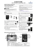
14 431A MBS/PDU (Distribution)
Purpose
The 431A is available in a MPS/PDU configuration. This unit
consiss of 12-pole PDU in the top section, and a SKRU (So-
lenoid Key Release Unit) MBS below it. See figure 14.1.
If one of the magnets does not latch firmly, or the spacing is too
narrow, bend one or the other of the magnetic latch supports
in or out as required to ensure a good fit. See Figure 14-1.
Repeat Step 14-3 and 14-4 for the F/B kick plate at the back of
the UPS.
Remove the F/B kick plates from the C-channel base skids.
No.
Part
1
Upper (PPD) Front Cover Mounting
Slots
2
Lower (MBS) Front Cover Mounting
Slots
3
PDU Circuit Breaker Panel
4
1
Cable Anchor Brace
5
SKRU for MBS
6
TB1
7
PCB1 - Power Board for SKRU
8
MBS Bus Stubs
9
MBS with Keyed Mechanical Lockout
10
Ground Bus Strip
11
Side Cable Access
12
Bottom Cable Access
13
C-Channel Base
1 - Secure the cables with cable ties to the Cable Anchor
Brace. This will provide strain relief for the upper power
bus strips.
4
3
5
8
7
6
9
13
11
10
12
1
1
1
1
2
2
2
2
11
Figure 14-1 - 4400 MBS/PDU with Front Panels
Removed