– 9 –
GENERAL ADJUSTMENTS
SPECIFIC INFORMATIONS
4. SELECTING THE ADJUSTING ITEMS
1) Every pressing of CHANNEL
s
button in the service mode changes the adjustment items in the order of table-2.
(
t
button for reverse order)
Refer to table-2 for preset data of adjustment mode.
(See SETTING & ADJUSTING DATA on page 17)
5. ADJUSTING THE DATA
1) Pressing of VOLUME
s
or
t
button will change the value of data in the range from 00H to FFH. The variable range
depends on the adjusting item.
6. EXIT FROM SERVICE MODE
1) Pressing POWER button to turn off the TV once.
■
INITIALIZATION OF MEMORY DATA OF QA02
After replacing QA02, the following initialization is required.
1. Enter the service mode, then select any register item.
2. Press and hold the RECALL button on the Remote, then press the CHANNEL
s
button on the TV. The initialization of QA02
has been complated.
3. Check the picture carefully. If necessary, adjust any adjustment item above.
Perform “Programming Channel Memory” on the owner’s manual.
CAUTION: Never attempt to initialize the data unless QA02 has been replaced.
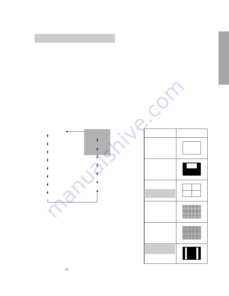
7. TEST SIGNAL SELECTION
1) Every pressing of TV/VIDEO button on the Remote Control in the Service mode, changes the built-in test patterns
on screen in the following order.
Normal picture
Black cross-bar
on green raster
Red raster
H signal (black)
H signal (white)
Green raster
Blue raster
White cross-dot
All black
Black cross-dot
All white
White cross-hatch
Black cross-hatch
White and black
Black cross-bar
White cross-bar
Signals
Picture
• Red raster
• Green raster
• Blue raster
• All Black
• All White
• Black & White
• Black cross-hatch
• White cross-hatch
• Black cross-dot
• White cross-dot
• Black cross-bar
• White cross-bar
• Black cross-bar
on green raster
• H signal (white)
• H signal (black)
Note: If the video cable is connected to the VIDEO1 INPUT jack, the
built-in pattern signals are not displayed.
*
The signals marked with
are not usable to display in the Test signal for some model.
Summary of Contents for 36AF61
Page 21: ... 21 SPECIFIC INFORMATIONS QZ01 DIG Comb ZY01 PIP Module CIRCUIT BLOCK DIAGRAM ...
Page 32: ...THIS PAGE IS INTENTIONALLY LEFT BLANK 32 SPECIFIC INFORMATIONS ...
Page 33: ... 33 34 SIGNAL BOARD PD0155 BOTTOM FOIL SIDE ...
Page 34: ... 35 36 POWER DEF BOARD PD0154 BOTTOM FOIL SIDE ...
Page 35: ... 37 CONTROL 1 BOARD PD0153 BOTTOM FOIL SIDE ...
Page 36: ... 38 CONTROL 2 BOARD PD0152 BOTTOM FOIL SIDE ...
Page 37: ... 39 CRT DRIVE BOARD PB9973 BOTTOM FOIL SIDE ...
Page 38: ... 40 3L DIGI COMB BOARD PB9398 BOTTOM FOIL SIDE ...


