TOSHIBA 2877 DB
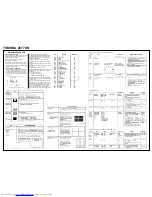
TEST SIGNAL SELECTION
Every pressing of
button in the service mode
changes the test patterns on screen as de-
scribed in SERVICE MODE.
Signal off NTSC signals (14 patterns)
PAL signals (14 patterns)
About inside signal: The inside signal is output
at video input terminal from QA01, and is not
output with the pin inserted into terminal. (Single
color signal can be output.)
SELF DIAGNOSTIC FUNCTION
1) Press “9” button on Remote Control during
display of adjustment menu in the service
mode. The diagnosis will begin to check if
interface among IC’s are executed properly.
2) During diagnosis, the following displays are
shown.
Adjustments Cont’d
(1) Part number of microcomputer (QA01)
(2) Operation number of protecting circuit “00”,
is normal.When indication is other than “00”,
overcurrent apts to flow, and circuit parts may
possibly be damaged.
(3) BUS LINE CHECK ----“OK” is normal.
“SDA1-GND” means that SDA line is shorted to
ground.
“SCL1-GND” means that SCL line is shorted to
ground.
“SCL1-SDA1” means that SDA line is shorted to
SCL line.
(4) BUS CONT ----“OK” is normal.
When indication shows “Q OOO NG”, the device
with the number may possibly be damaged.
(5) BLOCK
UV : TV reception mode
V1: VIDEO 1 input mode (
1)
V2: VIDEO 2 input mode (
2)
Indicated color of mode now selected : Green
and Red Indicated color of other modes : White
Green: Normal
Red: The microcomputer operates to provide
judgement of no video signal. The red color is
still indicated though the signal is input, failure
may exist in input signal line including QV01.
QV01: In case of indication green ---Normal
In case of indication red with input signal ----
Failure may exist in output line including QV01.
Model C7SS Series (Reference factory adjustment)
Model C7SS Series
Model C7SS Series (Only for the sets with SECAM function)
Summary of Contents for 3377 DB
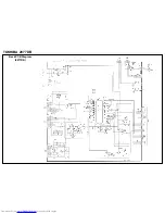
Page 3: ...TOSHIBA 2877 DB Back PCB Diagram 2877DB ...
Page 4: ...TOSHIBA 2877 DB Back PCB Diagram 3377DB ...
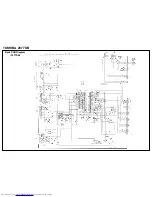
Page 5: ...TOSHIBA 2877 DB CRT Diagram 2877DB CRT Diagram 3377DB ...
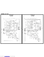
Page 6: ...TOSHIBA 2877 DB Dolby Diagram 2877DB ...
Page 7: ...TOSHIBA 2877 DB Dolby Diagram 3377DB ...
Page 8: ......
Page 9: ......
Page 10: ......
Page 11: ......


