background image

– 20 –

GENERAL ADJUSTMENTS

SPECIFIC INFORMATIONS

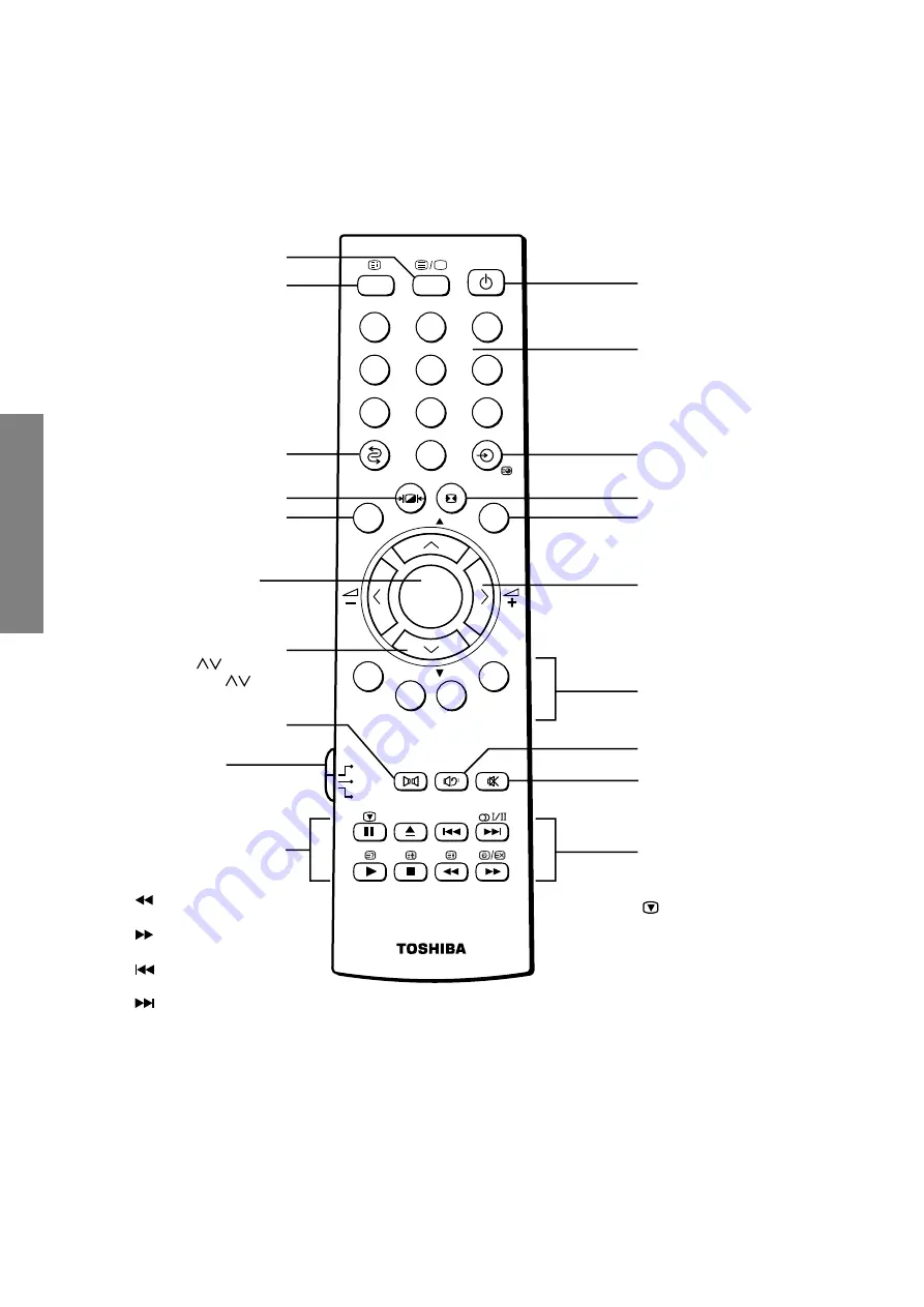
Remote Control

DVD

MENU

P

P

2

1

3

5

4

6

8

7

9

VCR

TV

DVD

0

OK

CALL

MENU

EXIT

Number buttons (0-9)

Sound mute

Input source selection
(

A

 1  –  

A

 4)

EXIT

Selectable sound

Power on/Standby

(For Toshiba TV/VCR/DVD only)

Device switch
TV: To control TV
VCR: To control VCR

DVD: To control DVD

Volume 


+

Menu 

<


>

DVD menu 

<


>

Bass boost on/off

When in TV mode:

m

I

/

II

Stereo/Bilingual

selection

Picture still

Channelposition 

st

Menu 

 [12]

DVD menu 

1 or 2 digit channel selection

CALL

Index, initial

Teletext buttons

Colored buttons

F + 

v

?

^

r

/

X

Selectable picture

MENU

DVD MENU

OK


DVD ENTER

Dolby Surround

When in VCR or DVD mode:
(For Toshiba VCR/DVD only)

c

to EJECT

to REWIND

S

to PLAY

to FAST FORWARD

J

to PAUSE
to SKIP-REWIND

R

to STOP

to SKIP-FORWARD

TEXT/TV

Summary of Contents for 32ZP38B

Page 1: ...FILE NO 030 200301 SERVICE MANUAL COLOUR TELEVISION ZP38 Chassis 36ZP38B 32ZP38B PUBLISHED IN JAPAN Mar 2003 So ...

Page 2: ...ENT 4 SERVICE MODE 6 DESIGN MODE 9 ELECTRICAL ADJUSTMENTS 10 CIRCUIT CHECK 17 CHAPTER 2 SPECIFIC INFORMATIONS SETTING ADJUSTING DATA 18 LOCATION OF CONTROLS 19 CHASSIS AND CABINET REPLACEMENT PARTS LIST 21 PC BOARDS BOTTOM VIEW 35 TERMINAL VIEW OF TRANSISTORS 44 CIRCUIT BLOCK DIAGRAM 46 SPECIFICATIONS END APPENDIX CIRCUIT DIAGRAM ...

Page 3: ... attempted by anyone unfamiliar with the necessary precautions on this receiver The following are the necessary precautions to be observed before servicing this chassis 1 An isolation transformer should be connected in the power line between the receiver and the AC line before any service is performed on the receiver 2 Always discharge the picture tube anode to the CRT conductive coating before ha...

Page 4: ...enly 6 Receive the green raster shift the deflection yoke from a foremost position hitting against the picture tube to a backward position horizontally stop the deflection yoke at a position where it begins to become a green raster and perform accurate marking on the picture tube 7 Shift the deflection yoke further backward and perform accurate marking at a position where the green raster begins t...

Page 5: ... TC S Blue color or blue mark Insert the correction piece between the picture tube and the deflection yoke Insertion position of correction piece Bonded surface blue green red Parts code 23 948 464 Bonded surface Adjust VR 1 and minimize the deviation of YH Only 27 30 and 32 Red green blue Red green blue Red green blue Red green blue Adjust VR 2 YHC and minimize the deviation of YH Red green blue ...

Page 6: ...Remote Change of the data value Volume on TV or Remote Adjustment menu mode ON OFF MENU button on TV Initialization of the memory QA02 CALL Channel button on TV s Reset the count of operating protect circuit to 00 CALL Channel button on TV t RCUT selection 1 button GCUT selection 2 button BCUT selection 3 button CNTX or SCNT selection 4 button COLC selection 5 button TNTC selection 6 button Self d...

Page 7: ...llowing initialization is required 1 Enter the service mode then select any register item 2 Press and hold the CALL button on the Remote then press the CHANNEL s button on the TV The initialization of QA02 has been complated 3 Check the picture carefully If necessary adjust any adjustment item above Perform Auto search Memory on the owner s manual CAUTION Never attempt to initialize the data unles...

Page 8: ...cted Green and Red Indicated color of other modes White Green Normal Red The microcomputer operates to provide judgement of no video signal The red color is still indicated though the signal is input failure may exist in input signal line including QV01 QV01 In case of indication green Normal In case of indication red with input signal Failure may exist in output line including QV01 NOTE Component...

Page 9: ...ign mode changes the adjustment items in the order of table 3 s button for reverse order Refer to table 3 for data of design mode See SETTING ADJUSTING DATA on page 18 3 ADJUSTING THE DATA Pressing of VOLUME s or t button will change the value of data When QA02 is initialized items OPT0 and OPT1 of DESIGN MODE are set to the data of the representative model of this chassis family Therefore because...

Page 10: ...t before the difference between the belt of vertical re trace and the border of black portion of inside pattern is visible After that return vertical height and con trast ITEM ADJUSTMENT PROCEDURE Belt of vertical retrace HORIZONTAL POSITION ADJUSTMENT HPOS VERTICAL POSITION ADJUSTMENT VPOS 1 Set the TV in service mode and get black cross bar signal with VIDEO button on remote hand unit 2 Select e...

Page 11: ...icture control 2 Receive the Black and White pattern 3 Select RCUT GCUT and BCUT with CHANNEL s t buttons to set individual values to Initial reference data and to set GDRV and BDRV to Initial reference data with VOLUME buttons See page 18 4 Press button on the remote control and rotate Screen VR to get one slight horizontal line on screen Note Every pressing of button provides Horizontal line pic...

Page 12: ...e at the time of adjustment 쩸 Enter Horizontal Straight line Mode 쩹 Gradually increase the screen VR until R G or B line starts to light up slightly 쩺 Determine this location as the adjusting position of the screen VR 쩻 Gradually raise the respective lines other than the line that glimmered in above and stop at the location where each of them glimmers Adjust so that it will become almost white 쩼 E...

Page 13: ...2 TP46B 쩸 Vary SBY so that the level of black and white signal areas will be aligned with that of BLK 쩸 Vary SRY so that the level of black and white signal areas will be aligned with that of H BLK 쩸 Adjust the amplitude of B Y Apply Y mute at the time of adjustment 0 10 mV 0 10 mV 1 6 0 1 Vo p Pedestal to Peak Items Names Settings Input signals Measuring points Adjusting methods Adjusting standar...

Page 14: ...position will come to the center in Philips Pattern See the figure on the right PAL Philips Pattern User Adjustment Standard Adjust the vertical amplitude position by HIT so that the top and bottom of the circle will contact the CPT mask in Philips Pattern See the figure on the right Philips Pattern User Adjustment Standard Adjust the vertical amplitude by HIT so that point shown in the lower righ...

Page 15: ...djustment standard Adjustment Use the sub focus volume R950 on the CRT drive printed circuit board and set it to the position where the longitudinal fly back lines of the corner area become minimized Repeat Items 1 and 2 above for adjustment to optimize the entire screen Conditions PAL WG Philips Pattern WIDE mode User Adjustment Standard Adjustment Use VPS1 and adjust so that the top and bottom p...

Page 16: ...tortion adjustment by PARA and TRAP was insufficient use the DATA of CNR CPAR CSAW and HSC for adjustment When the distortion occurs as shown in Fig a decrease CPAR On the contrary increase CPAR for the distortion of Fig b When the distortion occurs as shown in Fig c decrease CSAW On the contrary increase CSAW for the distortion of Fig d When the distortion occurs as shown in Fig e decrease HSC On...

Page 17: ...n accurate high voltage meter to the second anode of the picture tube 2 Turn on the receiver Set the BRIGHTNESS and CONTRAST controls to minimum zero beam current 3 High voltage must be measured below B kV Refer to table 1 for high voltage B See SETTING ADJUSTING DATA on page 18 4 Vary the BRIGHTNESS control to both extremes to be sure the high voltage does not exceed the limit under any condition...

Page 18: ...T BCUT GDRV BDRV BRTC COLP COLS SCC SRY SBY R CUTOFF G CUTOFF B CUTOFF R DRIVE B DRIVE SUB BRIGHT CEN SUB COLOR CEN PAL SUB COLOR CEN SECAM YOOUT LEVLE FOR FOR ATV SECAM R Y SECAM B Y Item Adjustment Reference data 40H 40H 40H 35H 35H 80H 19H 19H 1EH 07H 01H Item Adjustment Reference data WIDE SuperLive CINEMA HPOS HIT VLIN VPS2 WID PARA CNR TRAP CPAR HSC VPS1 CSAW H POSITION PICTURE HEIGHT V LINE...

Page 19: ...ar 5 L MONO R AUDIO VIDEO S VIDEO MENU P FIXED SURROUND OUT 4 R L R L L R AUDIO AUDIO PB CB Y PR CR 1 3 3S 2 SCART 1 SCART 2 SCART 3 VIDEO 4 COMPONENT VIDEO AUDIO OUT FIXED AERIAL TERMINAL SURROUND OUT VIDEO 5 S VIDEO VIDEO HEAD PHONE MAIN SWITCH POSITION UP POSITION DOWN VOLUME UP VOLUME DOWN EXIT ...

Page 20: ...VCR To control VCR DVD To control DVD Volume Menu DVD menu Bass boost on off When in TV mode mI II Stereo Bilingual selection Picture still Channelposition st Menu 12 DVD menu 1 or 2 digit channel selection CALL Index initial Teletext buttons Colored buttons F v r X Selectable picture MENU DVD MENU OK DVD ENTER Dolby Surround When in VCR or DVD mode For Toshiba VCR DVD only c to EJECT to REWIND S ...

Page 21: ...C 250V 33UF M 3A C447 24829273 PLASTIC FILM 400V 27000PF J C448 24640908 ELECTROLYTIC 160V 33UF M 3A LI C451 24503047 PLASTIC FILM 63V 0 33UF J C460 24679220 ELECTROLYTIC 250V 22UF M 3A C461 24503196 PLASTIC FILM CF92 T 1800VH 5600PF H C462 24666101 ELECTROLYTIC 16V 100UF M 3A C464 24503149 PLASTIC FILM 250V 3 3UF C465 24590183 PLASTIC FILM 50V 0 018UF J C466 24503261 PLASTIC FILM CF92 T 1250VH 68...

Page 22: ...24668102 ELECTROLYTIC 35V 1000UF M 3A C651 24668471 ELECTROLYTIC 35V 470UF M 3A C652 24668471 ELECTROLYTIC 35V 470UF M 3A C654 24503042 PLASTIC FILM 63V 0 12UF J C655 24503042 PLASTIC FILM 63V 0 12UF J C656 24232103 CERAMIC DISC 50V F 0 01UF Z C657 24797229 ELECTROLYTIC 50V 2 2UF M C660 24797229 ELECTROLYTIC 50V 2 2UF M C661 24797478 ELECTROLYTIC 50V 0 47UF M C662 24797229 ELECTROLYTIC 50V 2 2UF M...

Page 23: ...K 36ZP38B CA15 24105101 CERAMIC CHIP 50V CH 100PF J CA16 24105101 CERAMIC CHIP 50V CH 100PF J CA17 24105101 CERAMIC CHIP 50V CH 100PF J CA33 24793470 ELECTROLYTIC CE04G 10V 47UF M CA42 24794101 ELECTROLYTIC 16V 100UF M CA43 24109103 CERAMIC CHIP 50V B 0 01UF K CA44 24109103 CERAMIC CHIP 50V B 0 01UF K CA45 24109103 CERAMIC CHIP 50V B 0 01UF K CA67 24100103 CERAMIC CHIP 50V F 0 01UF Z CA68 24794100...

Page 24: ... 16V 100UF M 7L 3A CV09 24092538 CERAMIC CHIP 10V F 1UF Z CV10 24794100 ELECTROLYTIC 16V 10UF M CV12 24100104 CERAMIC CHIP 25V F 0 1UF Z CV13 24794100 ELECTROLYTIC 16V 10UF M CV14 24100104 CERAMIC CHIP 25V F 0 1UF Z CV15 24092743 CERAMIC CHIP 10V F 0 47UF Z CV23 24203101 ELECTROLYTIC 16V 100UF M 7L 3A CV24 24100104 CERAMIC CHIP 25V F 0 1UF Z CV25 24794470 ELECTORLYTIC 16V 47UF M CV35 24100104 CERA...

Page 25: ...ILM 1 6W 10K OHM J R487 24366474 CARBON FILM 1 6W 470K OHM J R488 24366154 CARBON FILM 1 6W 150K OHM J R489 24366104 CARBON FILM 1 6W 100K OHM J R491 24366101 CARBON FILM 1 6W 100 OHM J R492 24366472 CARBON FILM 1 6W 4 7K OHM J R495 24327224 METAL FILM 1 4W 220K OHM F R498 24366274 CARBON FILM 1 6W 270K OHM J R499 24366564 CARBON FILM 1 6W 560K OHM J R501 24011682 CHIP METAL FILM 1 20W 6 8K OHM J ...

Page 26: ... CARBON FILM 1 6W 220 OHM J R806 24381473 OXIDE METAL FILM 1 2W 47K OHM J R807 24366154 CARBON FILM 1 6W 150K OHM J R808 24019484 THERMISTOR PTC AC265 4R5A R810 24568159 CERAMIC COVERED 7W 1 5 OHM J R814 24366682 CARBON FILM 1 6W 6 8K OHM J R815 24552102 OXIDE METAL FILM 1 2W 1K OHM J R818 24019460 METAL PLATE 2W 0 1 OHM J R819 24381820 OXIDE METAL FILM 1 2W 82 OHM J R823 24552272 OXIDE METAL FILM...

Page 27: ...A19 24011331 CHIP METAL FILM 1 20W 330 OHM J RA20 24011102 CHIP METAL FILM 1 20W 1K OHM J RA22 24011331 CHIP METAL FILM 1 20W 330 OHM J RA23 24011331 CHIP METAL FILM 1 20W 330 OHM J RA24 24011331 CHIP METAL FILM 1 20W 330 OHM J RA25 24011102 CHIP METAL FILM 1 20W 1K OHM J RA26 24011102 CHIP METAL FILM 1 20W 1K OHM J RA27 24011102 CHIP METAL FILM 1 20W 1K OHM J RA28 24011102 CHIP METAL FILM 1 20W 1...

Page 28: ...LM 1 20W 10K OHM J RS01 24011562 CHIP METAL FILM 1 20W 5 6K OHM J RS02 24011562 CHIP METAL FILM 1 20W 5 6K OHM J RS03 24011562 CHIP METAL FILM 1 20W 5 6K OHM J RS04 24011562 CHIP METAL FILM 1 20W 5 6K OHM J RS05 24011562 CHIP METAL FILM 1 20W 5 6K OHM J RS06 24011562 CHIP METAL FILM 1 20W 5 6K OHM J RS07 24011562 CHIP METAL FILM 1 20W 5 6K OHM J RS08 24011562 CHIP METAL FILM 1 20W 5 6K OHM J RS09 ...

Page 29: ...V61 24552101 OXIDE METAL FILM 1 2W 100 OHM J RV62 24011101 CHIP METAL FILM 1 20W 100 OHM J RV63 24011102 CHIP METAL FILM 1 20W 1K OHM J RV64 24872750 CHIP METAL FILM 1 16W 75 OHM J RV65 24552101 OXIDE METAL FILM 1 2W 100 OHM J RV66 24872750 CHIP METAL FILM 1 16W 75 OHM J RV67 24011102 CHIP METAL FILM 1 20W 1K OHM J RV68 24011101 CHIP METAL FILM 1 20W 100 OHM J RV81 24872750 CHIP METAL FILM 1 16W 7...

Page 30: ...OIL PEAKING TRF4109AJ LC183 23289109 COIL PEAKING TRF41R0AF LD181 23103828 INDUCTOR BEAD TEM2121M LD182 23289470 COIL PEAKING TRF4470AF LD184 23103845 COIL TEM2030AY LG102 23103828 INDUCTOR BEAD TEM2121M LG103 23103828 INDUCTOR BEAD TEM2121M LJ901 23200547 COIL CORRECT COIL 0 4CU 60T TSB 2418AH 36ZP38B LR01 23289109 COIL PEAKING TRF41R0AF LR02 23289109 COIL PEAKING TRF41R0AF LT01 23103828 INDUCTOR...

Page 31: ...N Q840 23314141 TRANSISTOR 2SC3852 Q840B 70391355 SCREW BIND HEAD TAP TITE B BITTB 3X8 SZN Q901 23314780 TRANSISTOR 2SC4544 Q901B 70391355 SCREW BIND HEAD TAP TITE B BITTB 3X8 SZN Q902 23114433 TRANSISTOR 2SC1815 Y Q903 23314780 TRANSISTOR 2SC4544 Q903B 70391355 SCREW BIND HEAD TAP TITE B BITTB 3X8 SZN Q904 23114433 TRANSISTOR 2SC1815 Y Q905 23314780 TRANSISTOR 2SC4544 Q905B 70391355 SCREW BIND HE...

Page 32: ...CREW 3X10MM D406 23357366 DIODE FR105 B5 D415 23118094 DIODE EU2A D418 23316749 DIODE ZENER MTZJ30A D419 23316691 DIODE ZENER MTZJ10C D420 23316682 DIODE ZENER MTZJ7 5C D421 23316680 DIODE ZENER MTZJ7 5A D422 23316726 DIODE ZENER MTZJ15C D431 23316669 DIODE ZENER MTZJ5 1B D432 23316670 DIODE ZENER MTZJ5 1C D436 23115599 DIODE 1N4148 D441 23316687 DIODE ZENER MTZJ9 1B D442 23118094 DIODE EU2A D462 ...

Page 33: ...24000445 CHIP JUMPER 1608TYPE G604 24000445 CHIP JUMPER 1608TYPE G638 24011103 CHIP METAL FILM 1 20W 10K OHM J G675 24011333 CHIP METAL FILM 1 20W 33K OHM J G684 23118041 DIODE MA111 G828 23103145 FERRITE CHOKE TEM2011AA GA02 23103828 INDUCTOR BEAD TEM2121M GA10 23103828 INDUCTOR BEAD TEM2121M GA37 23103828 INDUCTOR BEAD TEM2121M GA38 23103828 INDUCTOR BEAD TEM2121M GA39 23103828 INDUCTOR BEAD TEM...

Page 34: ... Z896 23144539 PROTECTOR 491SERIES 125V 2A Z897 23144539 PROTECTOR 491SERIES 125V 2A ZD02 23103839 FERRITE CORE TFE1012 PC BOARD ASSEMBLIES U104 23786696 TEXT P2 BOARD PD0267 U901 23788245 CRT D BOARD PD0491G 36ZP38B U901 23788495 CRT D BOARD PD0491H 32ZP38B U902 23788246 SIGNAL BOARD PD1007A 36ZP38B U902 23788496 SIGNAL BOARD PD1007B 32ZP38B U903A 23788247 POWER BOARD PD1008A 1 36ZP38B U903A 2378...

Page 35: ... 35 36 SIGNAL BOARD PD1007 BOTTOM FOIL SIDE ...

Page 36: ... 37 38 POWER BOARD PD1008 1 BOTTOM FOIL SIDE ...

Page 37: ... 39 40 DEF BOARD PD1009 BOTTOM FOIL SIDE ...

Page 38: ...1 42 INDICATOR BOARD PD1008 2 BOTTOM FOIL SIDE EXT SP BOARD PD0206A BOTTOM FOIL SIDE TEXT P2 BOARD PD0267 BOTTOM FOIL SIDE CONTROL BOARD PD1008 3 BOTTOM FOIL SIDE DIGITAL IN BOARD PD0549B BOTTOM FOIL SIDE ...

Page 39: ... 43 CRT DRIVE BOARD PD0491 BOTTOM FOIL SIDE ...

Page 40: ...2SD1763A 2SC1569 2SC4544 2SA1788 2SA1306 2SA1186A 2SC752GTM 2SC2482 2SC2655 2SC4721P 2SC752 2SA562TM 2SA1015 2SC1815 2SC2878 2SC1740S 2SC2120 2SA9335 2SA1788 RN2203 RN2201 RN2004 RN1203 RN1204 RN2204 RN1205 RN1202 RN1201 2SD1554 2SD2253 2SD1556 2SC5143 2SD2553 E C B B C E BCE B C E E C B ON4409 B CE E C B B C E ...

Page 41: ...acitor 3 The parts indicated with have special characteristics and should be replaced with identical parts only 4 Voltages read with DIGITAL MULTI METER from point indicated to chassing ground using a color bar signal with all controls at normal line voltage 220 volts 5 Waveforms are taken receiving color bar signal with enough sensitivity 6 Voltage reading shown are nominal values and may vary 20...

Page 42: ...S B VOLTAGE AUTO LIVE UNIT RGB DIGI COMB MCD QZ01 Q501 QF01 Y C V Y C Y RGB C CHROMA VIDEO DEF Q501 Q302 Q4420 VIDEO OUT VM V OUT H OUT EW 100Hz F B T H V D Y V H CRT Q301 Q404 DPC Q901 Q903 Q905 1 2 S AV 3 I 2 C BUS CONTROL P r C R L R S V L R S HEAD PHONE EXT INT SPK SW Q670 AUDIO OUT Q640 AUDIO OUT SURROUND R SURROUND L EXT SPK L R CENTRE EXT SPK WOOFER TERM QK01 QK05 QR01 SUB µ CON DIG FRAME S...

Page 43: ... FB F6 21 69 X Z 2 S1 S41 PAL SECAM 50 Hz 60 Hz For Video Disk play back 4 43 NTSC For VCR playback 3 58 NTSC For VCR playback Intermediate Frequencies Picture I F carrier frequency 38 9 MHz L VL Sound I F carrier frequency B G System 33 4 MHz D K System 32 4 MHz Picture Tube 36 inches 860 mm measured on diagonal of viewable picture area 103 deflection Sound Output 10 W 10 W at 10 Distortion Main ...

Page 44: ...TOSHIBA CORPORATION 1 1 SHIBAURA 1 CHOME MINATO KU TOKYO 105 8001 JAPAN ...

Reviews: