background image

SERVICE MANUAL

COLOR TELEVISION

30HF84

FILE NO. 050-200418

Summary of Contents for 30HF84 - 30" CRT TV

Page 1: ...SERVICE MANUAL COLOR TELEVISION 30HF84 FILE NO 050 200418 ...

Page 2: ...which has the same character Especially as to the important parts for safety which is indicated in the circuit diagram or the table of parts as a mark the designated parts must be used 4 PUT PARTS AND WIRES IN THE ORIGINAL POSITION AFTER ASSEMBLING OR WIRING There are parts which use the insulation material such as a tube or tape for safety or which are assembled in the condition that these do not...

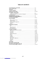
Page 3: ...S MAIN AV HD MI FRONT JACK CRT CONNECTOR SCHEMATIC DIAGRAMS CHROMA PROGRESSIVE PIN CUSHION DEFLECTION TV POWER OPERATION SOUND AMP FRONT AV MICON1 STEREO TUNER AV REGURATOR SYNC COUNT CONNECTOR CRT CVM INTERFACE MICON2 WAVEFORMS MECHANICAL EXPLODED VIEWS MECHANICAL REPLACEMENT PARTS LIST ELECTRICAL REPLACEMENT PARTS LIST A1 1 A1 1 A1 1 A2 1 A3 1 A3 5 B1 1 B2 1 B2 2 C 1 C 1 C 2 D 1 D 6 E 1 E 2 E 3 ...

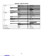
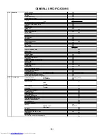
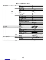
Page 4: ...E Tuning System F Synth Input Impedance VHF UHF 75 ohm 2 69 4A A 5 A 1 CH Coverage A I J W W 1 W 84 Intermediate Picture FP 45 75MHz Frequency Sound FS 41 25MHz FP FS 4 50MHz Preset CH No Stereo Dual TV Sound Yes Tuner Sound Muting Yes G 3 Power Power Source AC 120V AC 60Hz DC Power Consumption at AC 185 W at AC 120 V 60 Hz Stand by at AC 1 W at AC 120 V 60 Hz Per Year kWh Year Protector Power Fus...

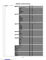
Page 5: ...rogram Yes Add Erase Yes Closed Caption Yes Picture Size Yes Picture Scroll Yes Cinema Mode Yes Aspect Yes Image Tilt Yes Option Yes Timer Yes Favorite CH Yes CH Label Yes VIDEO Label Yes Locks Yes V Chip Yes Lock Yes New Password Yes Front Panel Lock Yes Control Level Yes Volume Yes Contrast Yes Brightness Yes Color Yes Tint Yes Sharpness Yes Bass Yes Treble Yes Balance Yes Image Tilt Yes Picture...

Page 6: ...40 Keys Keys Power Yes 1 Yes 2 Yes 3 Yes 4 Yes 5 Yes 6 Yes 7 Yes 8 Yes 9 Yes 0 Yes 100 10 Yes CH Up Yes CH Down Yes Volume Up Yes Volume Down Yes TV Video Input Select Yes ENT CH RTN Quick View Yes Menu FAV Up Yes Menu FAV Down Yes Menu Up Yes Menu Down Yes Mute Yes PIC SIZE 16 9 Yes Light Yes Multi Brand Keys TV CBL SAT VCR DVD Yes DVD Keys Enter Yes TV DVD Keys SLEEP TOP MENU Yes RECALL Call Dis...

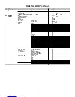
Page 7: ...Favorite CH Yes Variable Audio Out Yes Virtual Dolby No Picture Size Yes Color Temperature Control Yes Mode Picture Preference Yes Front Panel Lock Yes Available Scan Rates Component HDMI 480i 480p 720p 1080i Menu Volume Up Volume Down Yes Auto Setup Language CH Program Yes G 12 Accessories Owner s Manual Language English French W Warranty Yes Remote Control Unit Yes Rod Antenna No Poles Terminal ...

Page 8: ...udio L R RCA x 5 HDMI Input1 w Analog Audio L R HDMI x 1 RCA x 2 HDMI Input2 w Analog Audio L R No Diversity No Ext Speaker No VHF UHF Antenna Input F Type AC Outlet No G 14 Set Size Approx W x D x H mm 796 x 563 x 549 2 G 15 Weight Net Approx 54 0 kg 88 2 lbs Gross Approx 61 0kg 102 5lbs G 16 Carton Master Carton No Content Sets Material Dimensions W x D x H mm x x Description of Origin No Gift B...

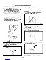
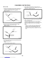
Page 9: ...ed Flip up the sides of the Rubber Cap in the direction of the arrow and remove one side of the support Refer to Fig 1 2 2 DISASSEMBLY INSTRUCTIONS GND on the CRT Screwdriver Alligator Clip Support CRT GND on the CRT Rubber Cap CRT Support Fig 1 1 Fig 1 2 3 After one side is removed pull in the opposite direction to remove the other NOTE Take care not to damage the Rubber Cap INSTALLATION 1 Clean ...

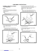
Page 10: ...using a blower type IC desoldering machine Refer to Fig 2 2 2 Fig 2 2 NOTE Do not add the rotating and the back and forth directions force on the IC until IC can move back and forth easily after desoldering the IC leads completely When IC starts moving back and forth easily after desoldering completely pickup the corner of the IC using a tweezers and remove the IC by moving with the IC desoldering...

Page 11: ...2 8 Thin tip Soldering Iron NOTE When the IC leads are bent during soldering and or repairing do not repair the bending of leads If the bending of leads are repaired the pattern may be damaged So always be sure to replace the IC in this case Finally confirm the soldering status on four sides of the IC using a magnifying glass Confirm that no abnormality is found on the soldering position and insta...

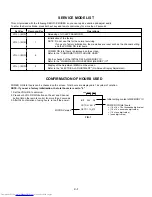
Page 12: ... DATA of MEMORY IC Refer to the WHEN REPLACING EEPROM MEMORY IC VOL MIN Display of the Adjustment MENU on the screen Refer to the ELECTRICAL ADJUSTMENT On Screen Display Adjustment 9 CONFIRMATION OF HOURS USED POWER ON total hours can be checked on the screen Total hours are displayed in 16 system of notation NOTE If you set a factory initialization the total hours is reset to 0 1 2 3 Set the VOLU...

Page 13: ...shipping Turn POWER on Press both VOL DOWN button on the set and Channel button 1 on the remote control for more than 2 seconds After the finishing of the initializing of shipping the unit will turn off automatically DF A2 01 C0 A6 1C 86 B8 42 E4 0 1 2 3 4 5 6 7 8 9 A B C D E F INI 01 1F 24 40 45 5D 62 45 4A 8F 00 00 00 00 00 00 00 00 19 77 05 07 21 10 07 00 22 74 81 8F 40 00 27 0A 2A 00 13 C0 B3 ...

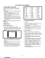
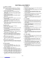
Page 14: ...est for more than 10 minutes Receive the gray scale pattern from the Pattern Generator Using the remote control set the brightness and contrast to normal position Activate the adjustment mode display of Fig 1 1 and press the channel button 24 on the remote control to select R BIAS Press the CH UP DOWN button on the remote control to select the R BIAS G BIAS B BIAS R G DRV B R DRV R BIAS C G BIAS C...

Page 15: ...g 1 1 and press the channel button 00 on the remote control to select OSD H Press the LEFT RIGHT button on the remote control until the difference of A and B becomes minimum Refer to Fig 2 2 2 5 HORIZONTAL POSITION HORIZONTAL SIZE 1 2 3 4 5 6 7 8 9 10 Receive the monoscope pattern Press the MENU button And then press the LEFT RIGHT button on the remote control until the PICTURE menu appears Press ...

Page 16: ...8 9 10 11 Receive the monoscope pattern RF Input Set the screen mode to FULL Using the remote control set the brightness and contrast to normal position Activate the adjustment mode display of Fig 1 1 and press the channel button 43 on the remote control to select BRI CENT Press the VOL UP DOWN button on the remote control until the white 30 is starting to be visible Receive the monoscope pattern ...

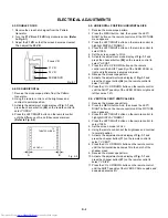
Page 17: ...he HD MI mode Then perform the above adjustments 2 8 Fig 2 3 A Fig 2 4 2 15 Confirmation of Fixed Value Step No Please check if the fixed values of the each adjustment items are set correctly referring below FUNCTION V POSI V EHT H EHT V BLK P V BLK S V LIMIT V CORR C S CORR S CORR CORNER C PARA C SAW V SYMM R Y GAIN R Y PHASE G Y GAIN G Y PHASE BRI MAX BRI MIN CONT CENT CONT MAX CONT MIN COL MAX ...

Page 18: ...performing adjustments in section 3 1 1 2 3 4 5 Receive the green raster pattern from color bar generator Adjust the pair of purity magnets to center the color on the screen Adjust the pair of purity magnets so the color at the ends are equally wide Move the deflection yoke backward to neck side slowly and stop it at the position when the whole screen is green Confirm red and blue color Adjust the...

Page 19: ...J707 J708 J709 CP702B CP103 CP102 CP509 CP605 CP101 CP2201 CP1001 CP704 CP711 CP712 CP803 R842 R834 CP804 R801 CP808B TP805 TP806 TP804 CP852 CP853 S853 S854 CP802B CP801 CP851B J2201 CD2201 CD1003 CD1001 CD1004 J2202 J2203 J2204 FRONT JACK PCB J801 CD501 AC IN CD504 MAIN PCB AV PCB PCB HD MI PCB CONNECTOR PCB CP703B CP404 CRT CD509 DEGAUSS COIL SPEAKER VM COIL PCB CRT CRT PCB CRT CRT CP703A CP702...

Page 20: ...T JACK AV SENC COUNT CONNECTOR V801 CRT J801 8 6 11 PROGRESSIVE IC IC603 TA1360ANG R OUT 43 BUFFER Q606 AMP Q802 Q811 G OUT 42 BUFFER Q607 AMP Q801 Q810 B OUT 41 BUFFER Q608 AMP Q803 Q812 VSM OUT 54 BUFFER Q605 AMP Q858 Q859 DY VP OUT 27 H OUT 26 FL OUT Q403 Y2 IN 8 2 4 5 39 38 31 37 21 6 PIN CUSHION IC602 TA1317ANG 7 5 V OUTPUT IC401 LA78041 30 19 55 Y_OUT Pb_OUT Pr_OUT OSD_R OSD_G OSD_B SDA1 SCL...

Page 21: ... AV SYNC COUNT CONNECTOR 2 FRONT JACK J2204 FRONT_A_IN_R 27 28 33 11 14 31 12 15 10 24 29 30 25 26 AUDIO_MUTE SOUND B 2 FRONT JACK J2203 2 FRONT JACK J2202 4 FRONT JACK J2201 3 6 FRONT_A_IN_L FRONT_V_IN FRONT_S_C FRONT_S_Y FRONT_S_SW INV1 OAOUT1 INV2 OAOUT2 VDDA MUTE VDD1 VDD1 VDD2 VDD2 VOUTP1 OUTM1 OUTM2 VOUTP2 TV E 3 E 4 ...

Page 22: ...EP_DATA CP103 6 TX BUSY 6 7 CLK RX 2 3 VCC 5 8 9 CNVSS RESET MICON_DATA CP102 RTS0 38 DRV Tx 35 CLK0 37 SAP TONE RESET 63 CNVss 9 DRV Rx 36 D101 STEREO IC902 MSP3440G QA C12 SC4_IN_R 48 CS2_A_IN_L SC3_IN_R 51 SWD_A_IN_L SC2_IN_L 53 SC1_IN_R 57 SC1_IN_L 56 DVI_A_L DAC_A_L DAC_A_R SC2_IN_R SC3_IN_L 50 54 SDA1 3 SCL1 2 SWD_A_IN_R DVI_A_R SC1_OUT_L 36 37 SC1_OUT_R VAR_A_OUT_L VAR_A_OUT_R SC4_IN_L 47 C...

Page 23: ..._IN_L Pb 1 Y 1 41 43 C CVBS V_AV 33 37 Pr 1 CP705 39 30 CS2_A_IN_L CS2_A_IN_R IN3A IN1A IN2A IN2B IN1B IN3B IN1B IN3B IN2B IN1A IN2A IN3A OUT1 OUT2 OUT3 Cb_IN Cr_IN D_SYNC1_IN Cr_OUT Cb_OUT Y_OUT IN2 IN1 OUT R_OUT L_OUT 1 4 2 P CON 5V OUT IC3401 KIA278O05PI IN SW OUT 1 4 2 P CON 3 3V OUT IC3402 KIA278R33PI IN SW OUT 1 4 2 P CON 9V OUT IC3400 KIA78R09PI IN SW OUT MICON1 STEREO DVI_A_R DVI_A_L DAC_A...

Page 24: ...D HDMI CONNECTOR CP3601 6 D1 4 D1 12 10 CLK CLK 3 D2 1 D2 13 Pb 14 Y 7 8 12V DAC_A_L 1 5V 2 AUDIO L 16 Pr CP3602 3 10 12 DAC_A_R 4V AUDIO R 2 3 1 2 3 1 3 3VREG IC3601 KIA78D33F 2 3 1 3 3VREG IC3602 KIA78D33F BUFFER Q3603 6 7 5 8 SDA SCL WP VCC 3 2 4 1 BUFFER Q3604 SW Q3612 SW Q3613 Audio_In_L J3601 Audio_In_R J3602 4 3 1 2 L3601 ACM2012D L3603 ACM2012D L3602 ACM2012D L3604 ACM2012D 4 3 1 2 4 3 1 2...

Page 25: ...TA SCLK LRCLK MCLK AOUT L VA AOUTR 3 8 7 6 EEP ROM IC IC3608 BR24L32F WE2 5 15 14 3 CSDA 2 CSCL BUFFER Q3605 4 SW IC3612 SN74AHC1G08DCKR 1 INTERFACE V_SYNC INTERFACE H_INT RXT_RST 5V CSDA BUFFER Q3606 CSCL 5 7 8 3 1 AUDIO_AMP IC3604 NJM4580M 18 MUTE_CTL MUTE SW Q3608 MUTE SW Q3610 MUTE SW Q3611 DAC_A_L DAC_A_R SDO SCK WS MCLK 12V X1 X2 2 1 4 6 4 GND A0 A1 A2 GND VCC WP SDA SCL E 11 E 12 ...

Page 26: ...0 L402 C433 R468 R477 R478 R479 R481 W006 R 48 3 D412 C436 C434 D402 C403 R405 R403 R401 D408 W003 C446 D415 R485 C431 L407 W015 W002 R404 D417 B404 C426 W004 C425 R413 R436 R411 D409 B405 D406 R417 D404 C407 C405 R407 C409 D403 R 40 6 R486 R487 R442 R431 R427 W802 W021 R441 W007 W014 D421 D422 W829 IC602 IC603 R547 C538 R602 C624 L602 W018 R631 R634 X603 R610 R671 CD603 R445_1 C640 C645_1 L607 C6...

Page 27: ... R643 R640 R648 C641 R649 C639 R646 R627 C605 R633 C656 C675 Q605 R652 R662 C679 R676 R675 R639 C657 C666 C658 R656 R659 R654 Q608 Q607 Q606 R624 R622 R616 C673 C662 C663 C664 C669 R660 R661 R685 R684 R686 C646 R642 R651 R647 Q611 R668 R669 Q603 R637 R678 Q612 R679 Q613 R650 R680 R657 C510 R677 R534 R533 C647 R537 C562 C564 R549 R1099 Q1099 R1098 Q1098 R1097 Q2001 R689 R688 R692 Q615 Q617 Q616 R69...

Page 28: ...18 W119 W120 C3409 W121 W122 W123 W124 HS3400 C780 C781 W807 W125 W126 W128 W129 W130 L3402 C3401 C3410 W131 W132 D109 C3403 W133 W134 W136 W138 HS3401 C3407 C3404 W139 IC3401 W140 C3414 W141 W142 R794 R795 W135 W828 W096 W111 W838 W815 W809 W805 W834 W810 W804 W819 C3415_1 D3403 D3404 W073 W820 R115 C006 I C 9 0 2 IC702 IC706 C908 C907 C902 C903 C904 C909 C910 C938 C002 R001 R002 R004 R005 Q703 Q...

Page 29: ...657 C3667 C3672 R3661 R3663 C3675 R3660 C3673 B3611 B3610 Q3606 Q3605 R3669 L3604 L3602 L3603 L3601 C3641 C3613 C3614 C3622 C3619 C3617 C3618 C3620 C3625 C3626 C3604 C3628 C3632 C3658 C3680 IC3608 W812 W813 CP3604 D3601 D3603 IC3607 R3636 W820 W818 W819 IC3605 C3652 C3651 C3650 CP3601 C3605 C3606 C3607 C3608 C3609 C3610 C3627 C3631 R3607 R3606 C3647 C3646 R3630 C3649 R3622 R3651 IC3602 C3657 C3656...

Page 30: ... 8 D803 R818 C804 R804 L805 R817 R801 R828 W828 Q803 HS803 R826 Q801 HS801 HS802 Q802 R819 R820 R825 D808 W001 D809 R824 D807 W006 W003 Q804 Q814 C801 R807 R805 R848 R823 R849 R809 CP808B R884 D801 W008 W007 W013 W014 W016 W009 W004 W808 Q810 Q811 TP805 TP806 TP804 W822 C809 C864 C855 W012 W015 CP852 L808 L810 L809 CP801 CP 85 1B CP853 S853 S854 Q812 R821 C806 R822 C814 C816 C815 W018 W801 C820 C8...

Page 31: ... balloon number in the schematic diagram NOTE 1 2 3 6 7 10 9 4 10µs 0 5V 10µs 1 0V 10µs 1 0V 10µs 1 0V 10µs 0 5V 10µs 1 0V 20µs 1 0V 5ms 1 0V 5 10µs 0 5V 8 10µs 0 5V DEFLECTION 11 5ms 1 0V 12 20µs 2 0V 5ms 1 0V 13 5ms 5 0V 14 5ms 200m 15 CHROMA PROGRESSIVE PIN CUSHION SOUND AMP FRONT AV ...

Page 32: ...lloon number in the schematic diagram NOTE WAVEFORMS MICON1 5ms 200m 16 5ms 1 0V 17 21 19 5ms 1 0V 18 5ms 1 0V 20 5ms 1 0V 0 5ms 1 0V 22 STEREO 20ms 1 0V 23 SYNC COUNT CONNECTOR 26 20ms 1 0V 24 20ms 1 0V 25 20ms 1 0V 27 20ms 200mV 28 10ms 200mV 29 20µs 1 0V 30 20µs 1 0V 5ms 1 0V ...

Page 33: ...sponding balloon number in the schematic diagram NOTE 31 20µs 1 0V 33 20µs 1 0V 34 20µs 1 0V 35 20µs 1 0V 39 20µs 50V 40 41 42 10µs 200mV 43 500µs 200mV 20µs 1 0V 36 20µs 50V 37 20µs 50V 38 10µs 200mV 10µs 200mV CRT CVM 32 20µs 1 0V 44 500µs 200mV 45 500µs 1 0V INTERFACE MICON2 ...

Page 34: ...H 4 The following waveforms were measured at the point of the corresponding balloon number in the schematic diagram NOTE WAVEFORMS 46 500µs 1 0V ...

Page 35: ... 101A 204 204 204 115 204 115 PCB260 FRONT JACK PCB ASS Y 211 211 122 122 202 202 119 118 114 119 118 205 205 134 202 202 119 118 114 119 118 205 205 134 116 101I 101H 101J 204 204 120 133 132 112 203 203 203 203 117 117 117 117 210 208 208 208 PCB110 CRT PCB ASS Y 108 111 PCBD80 VM COIL PCB ASS Y 107 ...

Page 36: ...01 201 201 102A 102 201 109 102C 102C 102B 201 201 201 201 201 110 205 206 205 105 106 207 207 113 PCBDJ0 HD MI PCB ASS Y PCBD20 AV PCB ASS Y 208 208 207 207 207 104 103 103 210 208 208 208 208 209 209 209 PCB070 MAIN PCB ASS Y 121 ...

Page 37: ...125 126 123 124 128 129 130 131 TM101 124 MECHANICAL EXPLODED VIEW PACKING DIAGRAM I 3 ...

Page 38: ...KER 115 AE004839 761WPA0294 COIL HOLDER 116 AE004840 761WPA0325 HOLDER PCB RAIL 117 AE004055 769WSA0016 WASHER CRT T 0 5 118 AD300518 801WR00001 DAMPER SPEAKER 119 BZ710445 82A40B0104 FLAT WASHER 120 AE004841 890DL20000 DOOR LATCHES DL2 121 BZ710260 899HV3T000 HOLDER ANODE WIRE 122 AE005209 761WPA0334 HOLDER CRT 123 AE000636 791WHA0102 LAMIFILM BAG 124 AE004842 792WHA0552 PACKAGE TOP 125 AE004843 ...

Page 39: ...330 OHM 2W R530 AE004810 R5X2CF010J R CEMENT 1 OHM 10W R545 AE003270 R3X28B2R7J R METAL OXIDE 2 7 OHM 3W R548 BZ210051 R3X18AR47J R METAL OXIDE 0 47 OHM 2W R560 AE005234 R5X2AER47J R CEMENT 0 47 OHM 7W R801 BZ210154 R5X2CE332J R CEMENT 3 3K OHM 7W R834 BZ210154 R5X2CE332J R CEMENT 3 3K OHM 7W R842 BZ210154 R5X2CE332J R CEMENT 3 3K OHM 7W R855 BZ210185 R65582151J R FUSE 150 OHM 1 2W R881 BZ210246 R...

Page 40: ... BZ410037 D97U03301B DIODE ZENER MTZJ33B T 77 D415 BZ410063 D2WTAU02A0 DIODE SILICON AU02A EIC D417 AE004359 D97U03901B DIODE ZENER MTZJ39B T 77 D418 BZ410037 D97U03301B DIODE ZENER MTZJ33B T 77 D420 BZ410094 D97U01501B DIODE ZENER MTZJ15B T 77 D421 AE004790 D2WX0216E0 DIODE SILICON RGP02 16E D422 AE004790 D2WX0216E0 DIODE SILICON RGP02 16E D501 BZ410031 D6CE24110A DIODE VARISTA ENE241D 10A Q6 D50...

Page 41: ...D97U01201B DIODE ZENER MTZJ12B T 77 D619 AD300070 D97U01201B DIODE ZENER MTZJ12B T 77 D621 BZ410034 D97U01301B DIODE ZENER MTZJ13B T 77 D622 AD300070 D97U01201B DIODE ZENER MTZJ12B T 77 D701 BZ410058 D97U08R21B DIODE ZENER MTZJ8 2B T 77 D702 BZ410021 D97U05R61B DIODE ZENER MTZJ5 6B T 77 D703 BZ410021 D97U05R61B DIODE ZENER MTZJ5 6B T 77 D704 BZ410022 D97U06R81B DIODE ZENER MTZJ6 8B T 77 D705 BZ410...

Page 42: ...0 Q Q403 AE004386 TCKF059040 TRANSISTOR SILICON 2SC5904000LI Q404 AE002626 T8YJ2412K0 TRANSISTOR SILICON 2SC2412KT146 R S Q405 BZ510020 TNYJB05001 COMPOUND TRANSISTOR DTC114EKAT146 Q406 BZ510020 TNYJB05001 COMPOUND TRANSISTOR DTC114EKAT146 Q410 AE002626 T8YJ2412K0 TRANSISTOR SILICON 2SC2412KT146 R S Q413 BZ510069 TCATC31980 TRANSISTOR SILICON KTC3198 AT Y GR Q414 AE002626 T8YJ2412K0 TRANSISTOR SIL...

Page 43: ...2626 T8YJ2412K0 TRANSISTOR SILICON 2SC2412KT146 R S Q1099 AE002626 T8YJ2412K0 TRANSISTOR SILICON 2SC2412KT146 R S Q2001 BZ510067 TNAAC05002 COMPOUND TRANSISTOR KRC103SRTK Q3403 AD301934 TBA0013660 TRANSISTOR SILICON KTB1366 O Y Q3404 BZ510022 TNYJJ05001 COMPOUND TRANSISTOR DTC114TKAT146 Q3603 BZ510113 T27T030180 FET 2SK3018 Q3604 BZ510113 T27T030180 FET 2SK3018 Q3605 BZ510113 T27T030180 FET 2SK301...

Page 44: ...E004758 060J401106 RCA JACK MTJ 032 03A 32FE J2204 AE004757 060J401105 RCA JACK MTJ 032 03A 31FE J3601 AE002950 060J421037 RCA JACK MTJ 032 05A 32 FE J3602 AE002951 060J421030 RCA JACK MTJ 032 05A 31 FE SWITCHES SW2001 BZ612010 0504101T34 SWITCH TACT EVQ21505R SW2002 BZ612010 0504101T34 SWITCH TACT EVQ21505R SW2003 BZ612010 0504101T34 SWITCH TACT EVQ21505R SW2004 BZ612010 0504101T34 SWITCH TACT EV...

Page 45: ...AD301996 069S330010 CONNECTOR PCB SIDE A2361WV2 3P CP804 BZ614058 069W010010 CONNECTOR PCB SIDE 005P 2100 CP852 BZ614350 069S230629 CONNECTOR PCB SIDE A2001WV2 3P CP853 BZ614349 067U003029 WIRE HOLDER B2013H02 3P CD1001 AE004772 06CU241802 CORD CONNECTOR CU241802 CD1003 AE004773 06CU263001 CORD CONNECTOR CU263001 CD1004 AE004771 06CU143801 CORD CONNECTOR CU143801 CD2201 AE004775 06CU283001 CORD CO...

Page 46: ...1300501 CRT W DY W76MAG185X80 X103 AE004780 100WT01611 CRYSTAL HC 49 U S X603 AE004348 1002R01502 CERAMIC OSCILLATOR CSBLA503KECZF30 B0 X701 AE004348 1002R01502 CERAMIC OSCILLATOR CSBLA503KECZF30 B0 X702 AE004349 100CT3R536 CRYSTAL HC 49 U X901 BZ613042 100CT01803 CRYSTAL HC 49 U S X3601 AE004779 100CT01101 CRYSTAL HC 49 U S RESISTOR RC CARBON RESISTOR CAPACITORS CC CERAMIC CAPACITOR CE ALUMI ELEC...

Page 47: ...TOSHIBA CORPORATION 1 1 SHIBAURA 1 CHOME MINATO KU TOKYO 105 8001 JAPAN ...

Reviews: