– 5 –
GENERAL ADJUSTMENTS
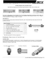
SPECIFIC INFORMATIONS
(5)Adjust the sub-4-pole magnets only in case there is any deviation of Xv bow-shaped convergence. (To be usually set at
the initial position)
Align both sides with the sub-4-pole magnets and minimize the deviation of blue and red with the main 4-pole magnets.
blue
blue
red
red
Main 4-pole magnet
red/blue
red/blue
green
green
6-pole magnet
Xv bow-shaped deviation of convergence
blue
red
Sub-4-pole magnet
■
CIRCUMFERENCE CONVERGENCE:
*
Perform correction in the following manner.
A
D
E
F
A
B
C
B
C
S
N
D
E
F
A
B
C
D
E
F
N
S
VR3
YV YHC
G
H
G
H
VR2 VR1
blue
green
red
• Adjust coils and minimize deviation
(The 27” unit has coils underneath it)
blue
green
red
(Parts code:23 948 274) TC-S
Blue color or blue mark
*Insert the correction piece between the
picture tube and the deflection yoke.
(Insertion position of correction
piece)
Bonded surface
blue
green
red
(Parts code:23 948 464)
Bonded surface
Adjust VR 1 and minimize the deviation of YH. *Only 27", 30" and 32".
Red
green
blue
Red
green
blue
Red
green
blue
Red
green
blue
Adjust VR 2 (YHC) and minimize the deviation of YH.
Red
green
blue
Red
green
blue
Red
green
blue
Red
green
blue
Adjust VR 3 (YV) and minimize the deviation of YV.
Red
blue
green
Red
blue
green
Red
blue
green
Red
blue
green
Red
blue
green
blue
red
green
Red
blue
green
blue
red
green
■
30", 27", 32"
■
34"
27" (Part No. 23 947 371)
32", 30" (Part No. 23 947 121)
34" (Part No. 23 993 080)
Perform correction by inserting the
correction piece into the clear-
ance of terminal board coils of
the deflection yoke.
Note:
Perform insertion by turning the
metal side to the terminal board
side of the deflection yoke.
Summary of Contents for 29SF6SH
Page 1: ...May 2003 FILE NO 070 200310 SERVICE MANUAL COLOUR TELEVISION D3ES Chassis 29SF6SH ...
Page 28: ... 28 SPECIFIC INFORMATIONS THIS PAGE IS INTENTIONALLY LEFT BLANK ...
Page 29: ... 29 30 MAIN BOARD PD1228 BOTTOM FOIL SIDE ...
Page 32: ... 34 GENERAL ADJUSTMENTS SPECIFIC INFORMATIONS THIS PAGE IS INTENTIONALLY LEFT BLANK ...