Toshiba 28Z33B, Service Manual
The Toshiba 28Z33B is a versatile television set with a sleek design and high-quality display. To enhance your user experience, make sure to download the Service Manual for detailed instructions and troubleshooting. This comprehensive manual is available for free download exclusively at manualshive.com, providing valuable insights to optimize your TV usage.
Share
Download


Reviews:
No comments
Related manuals for 28Z33B
LOG32LW782
Brand: Logik Pages: 47

32F8072-T
Brand: Finlux Pages: 41

VS14653-1M
Brand: ViewSonic Pages: 55

PS1980
Brand: Magnavox Pages: 32
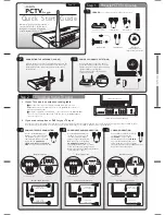
PCTV To Go
Brand: Pinnacle Pages: 2

TV GO
Brand: Disgo Pages: 11
V605-G3
Brand: Vizio Pages: 51

TFTV384HD
Brand: Palsonic Pages: 30

QSL322T
Brand: SONIQ Pages: 32

55 VLX 8720 BP
Brand: Grundig Pages: 15

i3SWEEZZ
Brand: i3-TECHNOLOGIES Pages: 5

43-FFD-4220
Brand: Finlux Pages: 44

LCD TV - 42 Inches and above
Brand: Onn Pages: 2

Viera TX-PF37X20
Brand: Panasonic Pages: 68

Viera TH-58PZ800E
Brand: Panasonic Pages: 56

Viera TX-LF37E30
Brand: Panasonic Pages: 104

TX-28LB1C
Brand: Panasonic Pages: 20

TX-29F225R-IRAN
Brand: Panasonic Pages: 44


