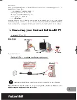


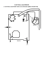


ELECTRICAL ADJUSTMENTS
1.
Read and perform these adjustments when repairing the
circuits or replacing electrical parts or PCB assemblies.
CAUTION
Use an isolation transformer when performing any
service on this chassis.
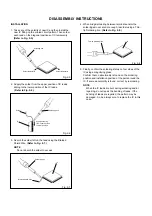
Before removing the anode cap, discharge electricity
because it contains high voltage.
When removing a PCB or related component, after
unfastening or changing a wire, be sure to put the wire
back in its original position.
When you exchange IC and Transistor for a heat sink,
apply the silicon grease on the contact section of the heat
sink. Before applying new silicon grease, remove all the
old silicon grease. (Old grease may cause damages to the
IC and Transistor.)
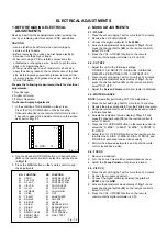
2. BASIC ADJUSTMENTS
2-1: RF AGC
Place the set with Aging Test for more than 15 minutes.
Receive the VHF HIGH (63dB).
Connect the digital voltmeter to the W043.
Activate the adjustment mode display of Fig. 1-1 and
press the channel button (02) on the remote control to
select "RF.AGC".
Press the VOL. UP/DOWN button on the remote
control until the digital voltmeter is 2.5
±
0.05V.
1.
2.
3.
4.
5.
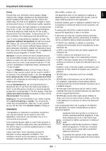
BEFORE MAKING ELECTRICAL
ADJUSTMENTS
2-2: CUT OFF
1.
2.
3.
4.
Adjust the unit to the following settings.
R.DRIVE=10, B.DRIVE=10, R.BIAS=64, G.BIAS=64,
B.BIAS=64, BRIGHTNESS=125, CONTRAST=60.
Place the set with Aging Test for more than 15 minutes.
Activate the adjustment mode display of Fig. 1-1 and
press the channel button (01) on the remote control to
select "CUT OFF".
Adjust the Screen Volume until a dim raster is obtained.
2-3: WHITE BALANCE
NOTE: Adjust after performing CUT OFF adjustment.
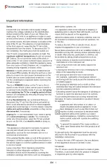
On-Screen Display Adjustment
In the condition of NO indication on the screen.
Press the VOL. DOWN button on the set and the
Channel button (9) on the remote control for more than
1 second to appear the adjustment mode on the screen
as shown in Fig. 1-1.
1.
Fig. 1-1
Use the Channel UP/DOWN button or Channel button
(0-9) on the remote control to select the options shown
in Fig. 1-2.
Press the MENU button on the remote control to end
the adjustments.
2.
3.
Prepare the following measurement tools for electrical
adjustments.
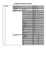
FUNCTION
OSD H
CUT OFF
RF AGC
VIF VCO
H.VCO
H.PHASE
V.SIZE
V.SHIFT
R.DRIVE
B.DRIVE
R.BIAS
G.BIAS
B.BIAS
BRIGHT CENT
BRIGHT MAX
BRIGHT MIN
NO.
00
01
02
03
04
05
06
07
08
09
10
11
12
13
14
15
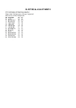
Fig. 1-2
FUNCTION
CONTRAST CENT
CONTRAST MAX
CONTRAST MIN
COLOR CENT
COLOR MAX
COLOR MIN
TINT
SHARPNESS
FM LEVEL
LEVEL
SEPARATION 1
SEPARATION 2
TEST MONO
TEST STEREO
X-RAY TEST
NO.
16
17
18
19
20
21
22
23
24
25
26
27
28
29
30
TV
00 OSD 15
2-5: VIF VCO
Place the set with Aging Test for more than 10 minutes.
Receive the monoscope pattern.
Connect the digital voltmeter between the pin 5 of
CP601 and the GND.
Activate the adjustment mode display of Fig. 1-1 and
press the channel button (03) on the remote control to
select "V.VCO".
Press the VOL. UP/DOWN button on the remote
control until the digital voltmeter is 2.5V.
1.
2.
3.
4.
5.
1. Oscilloscope
2. Digital Voltmeter
3. Pattern Generator
1.
2.
3.
4.
5.
6.
7.
Place the set with Aging Test for more than 10 minutes.
Receive the gray scale pattern from the Pattern Generator.
Using the remote control, set the brightness and contrast
to normal position.
Activate the adjustment mode display of Fig. 1-1 and
press the channel button (10) on the remote control to
select “R. BIAS”.
Press the CH. UP/DOWN button on the remote control to
select the “R. BIAS”, “G. BIAS”, “B. BIAS”, “R. DRIVE” or
“B. DRIVE”.
Adjust the VOL. UP/DOWN button on the remote control
to whiten the R. BIAS, G. BIAS, B. BIAS, R. DRIVE, and
B. DRIVE at each step tone sections equally.
Perform the above adjustments 5 and 6 until the white
color is looked like a white.
2-4: FOCUS
1.
2.
3.
Receive a broadcast.
Turn the Focus Volume fully counterclockwise once.
Adjust the Focus Volume until picture is distinct.
•
•
•
•