D4163443A
17
(2)
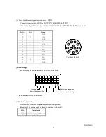
Power/synchronous signal input connector
DC IN
・
Connector (camera side) : HR10A-10R-12PB(71) (HIROSE ELECTRIC)
・
Compatible plug (cable side): Equivalent to HR10A-10P-12S(73) (HIROSE ELECTRIC) or equivalent
Pin No.
I/O
Signal
1
-
GND
2
I
+12V
3
-
GND
4
-
N.C.
5
-
GND
6
-
N.C.
7
-
N.C.
8
-
GND
9
-
N.C.
10
-
N.C.
11
I
TRIG
12
-
GND
[Switch setting]
Various settings are available with the dip switch on the back.
Memory bank specifi ed
Communication speed setting
Switching output mode
O
N
1
2
3
4
5
6
7
8
Unused
“*” indicates default setting at shipment.
(1) Switching output mode
Switch between Medium Configuration and Base Configuration.
The power of the camera needs be turned on again to switch modes.
SW1
Output mode
OFF
*
Medium Configuration
ON
Base Configuration
1
10
2
3
4
5
6
7
8
9
11
12
本体背面から見た図
View from the back
Summary of Contents for CSC12M25BMP19
Page 31: ...D4163443A 30 Note ...

