


Maintenance
53
2
1
3
M-4280
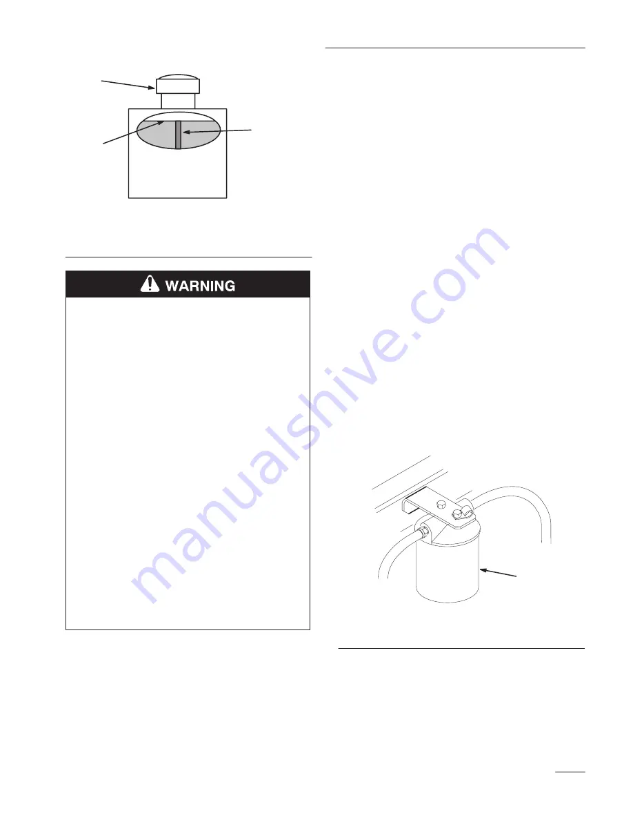
Figure 39
1.
Cap
2.
Baffle
3.
Fluid level-Full
POTENTIAL HAZARD
•
Hydraulic fluid escaping under pressure
can penetrate skin and cause injury.
WHAT CAN HAPPEN
•
Fluid accidentally injected into the skin
must be surgically removed within a few
hours by a doctor familiar with this form of
injury or gangrene may result.
HOW TO AVOID THE HAZARD
•
Make sure all hydraulic fluid hoses and
lines are in good condition and all
hydraulic connections and fittings are tight
before applying pressure to hydraulic
system.
•
Keep body and hands away from pin hole
leaks or nozzles that eject high pressure
hydraulic fluid.
•
Use cardboard or paper to find hydraulic
leaks.
•
Safely relieve all pressure in the hydraulic
system before performing any work on the
hydraulic system.
Replacing the Hydraulic Filter
Change the hydraulic filter:
•
After the first 8 operating hours.
•
After every 200 operating hours.
•
Use summer filter above 32
F (0
C)
Use winter filter below 32
F (0
C)
1.
Disengage the power take off (PTO) and turn the
ignition key to “OFF” to stop the engine. Move
controllers to neutral locked position and apply
parking brake. Remove the key.
IMPORTANT: Do not substitute automotive
oil filter or severe hydraulic system damage
may result.
2.
Tilt seat forward to access filter.
3.
Remove hydraulic reservoir cap and temporarily
cover opening with a plastic bag and rubber band
to prevent all hydro fluid from draining out.
4.
Place drain pan under filter, remove the old filter
and wipe the filter adapter gasket surface clean
(Fig. 40).
1
M-4384
Figure 40
1.
Hydraulic filter
5.
Apply a thin coat hydro fluid to the rubber
gasket on the replacement filter (Fig. 41).
6.
Install replacement hydraulic filter onto the filter
adapter. Do not tighten.
Summary of Contents for Z-Master Z252L
Page 10: ...Safety 8...
Page 11: ...Safety 9 Slope Chart Read all safety instructions on pages 5 7...
Page 12: ...10...
Page 74: ......
Page 75: ......


