Toro reelmaster 5300-d Operator'S Manual Download Page 17

17

STARTING AND STOPPING

IMPORTANT: The fuel system must be bled if
any of the following situations have occurred.

A.

Initial start up of a new machine.

B.

The engine has ceased running due to lack of

fuel.

C.

Maintenance has been performed upon fuel sys-

tem components; i.e., filter replaced, separator
serviced, etc.

Refer to Bleeding The Fuel System

1.

Sit on the seat, keeping your foot off the trac-

tion pedal. Assure the parking brake is engaged,
the traction pedal is in NEUTRAL, the throttle
is in the SLOW position and the ENABLE /
DISABLE switch is in the DISABLE position.

2.

Turn the ignition switch to the ON/Preheat posi-

tion. An automatic timer will control preheat
for 6 seconds. After preheat, turn the key to
START. CRANK THE ENGINE FOR NO
LONGER THAN 15 SECONDS.  Release the
key when the engine starts. If additional preheat
is required, turn the key to OFF then to the
ON/Preheat position. Repeat the process as
needed.

3.

Run the engine at idle speed or partial throttle

until the engine warms up. 

4.

To stop, move all controls to NEUTRAL and

set the parking brake.  Return the throttle to the
idle position, turn the key to OFF and remove it
from switch.  

BLEEDING THE FUEL SYSTEM

1.

Raise the hood over the engine.
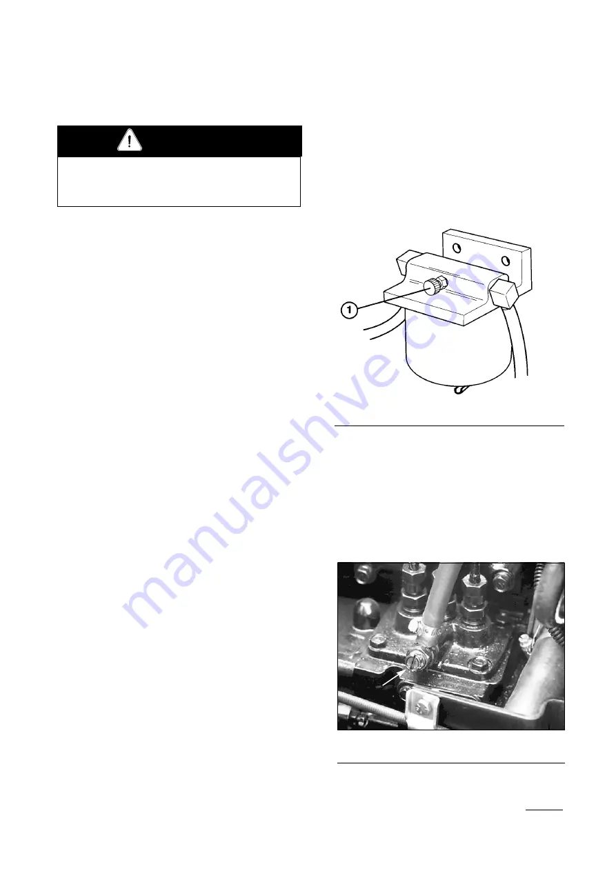
2.

Loosen the air bleed screw on top of the fuel fil-
ter/water separator (Fig. 15)

3.

Turn the key in the ignition switch to ON.  The
electric fuel pump will begin operation, forcing
air out around the air bleed screw.  Leave the
key in the ON position until a solid stream of
fuel flows out around the screw.  Tighten the
screw and turn the key to OFF.

4.

Open the air bleed screw on the fuel injection
pump with a 12 mm wrench.

Before servicing or making adjustments to the
machine, stop the engine and remove the key from
the switch.

CAUTION

Operation

Figure 15

1.

Air Bleed Screw

Figure 16

1.

Fuel injection Pump Bleed Screw

Summary of Contents for reelmaster 5300-d

Page 1: ...ttention to SAFETY INSTRUCTIONS highlighted by this symbol It means CAUTION WARNING or DAN GER personal safety instruction Failure to comply with the instruction may result in per sonal injury OPERATOR S MANUAL FORM NO 3318 590 GB Rev A MODEL NO 03530 60001 UP MODEL NO 03531 60001 UP REELMASTER 5300 D The TORO COMPANY 1995 ...

Page 2: ...NUMBER The model and serial number for the traction unit is on a plate that is mounted on the left front frame member The model and serial number for the cutting unit is on a plate that is mounted on the top front of the center cut ting unit Use model and serial number in all correspondence and when ordering parts To order replacement parts from an authorized TORO Distributor supply the following ...

Page 3: ...nt is to be used and remove all objects which may be thrown by the machine 3 WARNING Petrol is highly flammable Store fuel in containers specifically designed for this purpose Refuel outdoors only and do not smoke while refueling Add fuel before starting the engine Never remove the cap of the fuel tank or add petrol while the engine is running or when the engine is hot If petrol is spilled do not ...

Page 4: ... the grass catcher before making height adjustments unless the adjustment can be made from the opera tor s position before clearing blockages before checking cleaning or working on the lawnmower after striking a foreign object Inspect the lawnmower for damage and make repairs before restarting and operating the equip ment 15 Reduce the throttle setting during engine runout and if the engine is pro...

Page 5: ...power level of 103 5 dB A 1pW based on measurements of identical machines per procedures outlined in Directive 79 113 EEC and amendments Vibration Levels This unit has a vibration level of 2 5 m s2 at the pos terior based on measurements of identical machines per ISO 2631 procedures This unit does not exceed a vibration level of 0 5 m s2 at the posterior based on measurements of iden tical machine...

Page 6: ...t input drive line Fingers or hand entangle ment chain drive Runover back over relevant machine to appear in dashed box Machine tipping riding mower Machine rollover ROPS relevant machine to appear in dashed box Stored energy hazard kickback or upward motion Hot surfaces burns to fingers or hands Hand arm entanglement belt drive Thrown or fly ing objects whole body exposure Thrown or flying object...

Page 7: ... Slow Continuous variable linear Volume empty Volume full Machine travel direction forward rearward Control lever operating direction dual direction Control lever operating direction multiple direction Clockwise rotation Counter clock wise rotation Grease lubrication point Oil lubrication point Lift point Jack or support point Draining emptying Engine lubricat ing oil Engine lubricating oil pressu...

Page 8: ...l drive Power Take Off Power Take Off rotational speed Reel cutting element Reel cutting element height adjustment Traction Above working temperature range Drilling Manual metal arc welding Manual 0356 Water pump 0626 Keep dry 0430 weight Do not dispose in the garbage CE logo Engine coolant pressure Engine coolant f ilter Engine lubricating oil pressure Engine intake combustion air Engine intake c...

Page 9: ... rating Recommended tire pressure for the front and rear tires is 69 103 kPa 10 15 psi Brakes Individual drum type wheel brakes on the front traction wheels Brakes controlled by individ ual pedals operated by the left foot Hydrostatic braking through traction drive Electrical System Automotive type electrical sys tem 12 volt maintenance free battery with 530 cold cranking Amps 18 C 0 F and 85 minu...

Page 10: ... Height of Cut Kit Model No 83 5300 Scraper Comb Kit Model No 03518 Armrest Kit Model No 30707 Front Scraper HHOC Kit P N 82 6920 Thatcher Unit Model No 03516 Precleaner Bowl Extension Tube Part No 43 3810 Clamp Part No 20 4840 required to install exten sion tube 4 Wheel Drive Kit Model No 03517 For use with models 03502 03530 only 10 Specifications ...

Page 11: ... cooling system is filled with a 50 50 solution of water and permanent ethylene glycol anti freeze Check the level of coolant in the expansion tank each day before starting the engine Cooling system capacity is 9 6 l 1 Check the level of coolant in the expansion tank It should be between the marks on the side of the tank 2 If coolant level is low remove the expansion tank cap and replenish the sys...

Page 12: ...esigned to operate on anti wear hydraulic fluid The machine s reservoir is filled at the factory with 32 2 l 8 5 gal lons of Mobil 424 hydraulic fluid Check the level of hydraulic fluid before the first starting the engine and daily thereafter Group 1 Hydraulic Oil Recommended for ambi ent temperatures consistently below 38 C 100 F ISO type 46 68 anti wear hydraulic fluid Mobil Mobil Fluid 424 Amo...

Page 13: ...ype oils in the lower ambi ent temperatures may result in harder starting increased engine laboring while cold sluggish or non operating valve spools while cold and increased filter back pressure due to the higher oil viscosity Select the set of conditions either ambient tempera tures above 21 C 70 F or below 38 C 100 F and use that type of oil throughout the year rather than changing oil types se...

Page 14: ...vel is low remove a mounting bolt above each end plug and add enough lubri cant to bring the level up to the bottom of the hole Fig 7 3 Remove the plug in the center of the axle and check the level If the level is low add enough lubricant to bring it up to the bottom of the hole Fig 5 CHECK REEL TO BEDKNIFE CONTACT Each day before operating check the reel to bed knife contact regardless of whether...

Page 15: ...action pedal can be depressed in the forward direction to maintain a con stant mowing speed Lower Mow Raise Control Lever Fig 11 The lever raises and lowers the cutting units and also starts and stops the reels Speedometer Fig 11 Indicates ground speed at which the machine is traveling Fuel Gauge Fig 11 Shows the amount of fuel in the tank Engine Oil Pressure Warning Light Fig 11 Indicates dangero...

Page 16: ...etting informs the elec tronic controller at what height of cut the machine is being operated so desired clip may be obtained Hour Meter Fig 13 Shows the total hours the machine has been operated Brake Pedals Fig 14 Two foot pedals operate individual wheel brakes for turning assistance park ing and to aid in sidehill traction A Locking pin connects the pedals for parking brake operation and transp...

Page 17: ...ional preheat is required turn the key to OFF then to the ON Preheat position Repeat the process as needed 3 Run the engine at idle speed or partial throttle until the engine warms up 4 To stop move all controls to NEUTRAL and set the parking brake Return the throttle to the idle position turn the key to OFF and remove it from switch BLEEDING THE FUEL SYSTEM 1 Raise the hood over the engine 2 Loos...

Page 18: ...hieve a consistent high quality of cut and a uniform after cut appearance it is important that the reel speed be matched to the height of cut The machine controller is programmed to automatically control the reel speed to give the correct clip even as the traction speed changes To control the reel speed as desired the controller must know the height of cut of the machine and whether the machine is...

Page 19: ... one of the following things 1 The machine is being operated at a traction speed too slow to allow desired clip 2 The machine is being operated at a traction speed too fast to allow desired clip To correct the situation change the traction speed until the light goes out 19 Figure 17 1 Height of cut selector knob Operating Instructions CLIP RATE REEL SPEED SELECTIONS CHART 8 Blade Cutting Unit 5 Bl...

Page 20: ... in front of the seat and open the hood to gain access to all 5 springs 3 Place an open end wrench on the hex shaft of the spring bracket 4 Remove the capscrew and locknut securing retaining bracket while rotating hex shaft to relieve spring tension 5 Move the spring bracket to the desired location and install the capscrew and locknut while turning the hex shaft to relieve spring tension TOWING TH...

Page 21: ...Figure 21 1 Electron Controller Light When the controller diagnostic light blinks one of the following problems has been detected by the con troller 1 One of the outputs has been shorted 2 One of the outputs is open circuited Using the diagnostic display determine which output is malfunctioning refer to Checking Interlock Switches If the diagnostic light is not illuminated when the key switch is i...

Page 22: ...h to the ON position but do not start the machine Figure 23 1 Diagnostic ACE Note The red text on the overlay decal refers to input switches and the green text refers to outputs 5 The inputs displayed LED on lower right column of the Diagnostic ACE should be illu minated If outputs displayed LED is illumi nated press the toggle button on Diagnostic ACE to change LED to inputs displayed 6 The Diagn...

Page 23: ...one as often as required DO NOT HOLD THE BUTTON 6 Sit on the seat and attempt to operate the desired function of the machine The appropriate output LED s should illuminate to indicate that the ECU is turning on that function Note If any output LED is blinking this indi cates an electrical problem with that OUTPUT Repair replace defective electrical parts immediately To reset a blinking LED turn th...

Page 24: ...link indicating the ECU has shut off the cutting units CHECKING LEAK DETECTOR OPERATION The operation of the TurfDefender should be checked if any of the following conditions occur a No beeps are heard when the ignition switch is turned ON b Any time the machine gives a series of four short beeps c False alarms occur 1 Park the machine on a level surface stop the engine and engage the parking brak...

Page 25: ...sult your Authorized Toro Distributor for assistance Data Line LED Blinking Problem with communications between the machine and the leak detector or problem with wires Consult your Authorized Toro Distributor for assistance Note If the machine must be operable with leak detector disabled unplug the leak detector 4 pin connector from the 4 pin connector of the main harness Do not unplug the leak de...

Page 26: ... 4 LED is lit if the oil level is too high 5 LED is lit if a system air leak has been detected 6 One or two LED s are lit displaying the relative position of the Turfdefender s internal float 7 Inputs Displayed LED ON Red Normal Operation a Oil Level OK LED lit b 1 or 2 LEDs are lit on the left column Using Outputs Displayed Green Text Normal Operation a Valve ON LED lit steadily b Self Diagnostic...

Page 27: ...l gradually and intermittently until the uphill wheel stops slipping thus increasing trac tion on the downhill wheel Warning When operating the machine always use the seat belt and roll over protection system Warning System If a warning light comes on dur ing operation stop the machine immediately and cor rect the problem before continuing operation Serious damage could occur if the machine is ope...

Page 28: ...rpose Lithium Base Grease If the machine is operated under nor mal conditions lubricate all bearings and bushings after every 50 hours of operation Figure 27 Figure 28 Figure 29 Figure 30 Figure 31 Maintenance Before servicing or making adjustments to the machine stop the engine and remove the key from the switch CAUTION ...

Page 29: ...FLUID TYPE CAPACITY CHANGE FLUID CHANGE FILTER FILTER PART NO CAPACITY SAE 10W 30 3 7 l 50 hours 100 hours 67 4330 TRANSMISSION OIL Mobil 424 4 7 l 800 hours 800 hours 75 1330 HYDRAULIC CIRCUIT OIL Mobil 424 32 2 800 hours Where indicator is in red zone 75 1310 AIR CLEANER 400 hours 27 7110 FUEL PUMP 400 hours 43 2550 WATER SEPARATOR 400 hours 63 8300 FUEL TANK No 2 Diesel 37 9 l COOLANT 50 50 Eth...

Page 30: ...mp filter Replace the fuel water separator filter Inspect traction linkage movement Torque head and adjust valves Check engine rpm idle and full throttle Drain moisture hydraulic tank Drain moisture Fuel tank Check the reel bearing preload Torque wheel lug nuts Check fan and alternator belt tension Replace engine oil filter Inspect cooling system hoses Check battery fluid level Check battery cable...

Page 31: ...smission filter indicator2 12 Hydraulic hoses for drainage 13 Fluid leaks 14 Tire pressure 15 Instrument operation 16 Reel to bedknife adjustment 17 Height of cut adjustment 18 Cutting units shear pin 18 Lubricate all grease fillings3 19 Touch up damaged paint 1 Check glow plug and injector nozzles if hard starting excess smoke or rough running is noted 2 Check with the engine running and the oil ...

Page 32: ...l Figure 35 1 Dust Cup Baffle 3 Air Cleaner Body 2 Filter Element Figure 39 1 Fuel pump 2 Cover 32 Maintenance Figure 36 1 Engine Oil Drain Plug Figure 37 1 Engine Oil Filter Figure 38 1 Fuel Filter Water Separator 2 Drain plug 3 ...

Page 33: ...acts Clean it thoroughly with water or compressed air Figure 42 1 Oil Cooler 3 Transmission Oil Cooler 2 Radiator Figure 43 1 Alternator Belt Figure 44 1 Cooling Fan Belt 2 Tensioner Lever Figure 45 1 Injection Pump Lever Arm IMPORTANT Use only hydraulic oils specified Other fluids could cause system damage ...

Page 34: ...s released If it does creep an adjustment is required 1 Park the machine on a level surface shut the engine off and lower the cutting units to the floor Depress only the right brake pedal and engage the parking brake 2 Jack up the left side of the machine until the front tire is off the shop floor Support the machine with jack stands to prevent it from falling accidentally 3 Under the right side o...

Page 35: ...ont lift cylinder under the foot rest 2 Loosen the setscrew on the valve and rotate it 1 2 turn clockwise 3 Verify the lift rate adjustment by raising and lowering the cutting unit several times Readjust as required 4 After the desired lift rate is attained tighten the setscrew to lock adjustment Rear Cutting Units 1 Raise the hood and locate the valve on the left rear side of the machine 2 Loosen...

Page 36: ... shortened 3 mm 1 8 Tighten the hex nut 6 Operate the machine and check stopping dis tance Repeat procedure if required Note Shortening the distance between the inside of the eye bolt loop and the inside of the spring anchor plate increases the force on the traction pedal Do not over adjust CHANGING TRANSMISSION FLUID Change the transmission oil after every 800 hours of operation in normal conditi...

Page 37: ... 5 Fill the axle with lubricant REAR WHEEL TOE IN After every 800 operating hours or annually check the rear wheel toe in 1 Measure center to center distance at axle height at the front and rear of the steering tires The front measurement must be 3 mm less than the rear measurement 2 To adjust loosen the clamps at both ends of the tie rod 3 Rotate the tie rod s to more the front of the tire inward...

Page 38: ...est speed for backlapping Position A will pro vide the fastest speed for backlapping New motors will generally backlap at position P but with time the set point may need to be moved closer to A to account for motor wear 10 To make an adjustment to the cutting units while backlapping turn the reels OFF by mov ing the Lower Mow Raise lever rearward move the Enable Disable switch to Disable and turn ...

Page 39: ...ess tighten as necessary 4 Grease or oil all grease fittings and pivot points Wipe up any excess lubricant 5 Lightly sand and use touch up paint on painted areas that are scratched chipped or rusted Repair any dents in the metal body 6 Service the battery and cables as follows a Remove the battery terminals from the bat tery posts b Clean the battery terminals and posts with a wire brush and bakin...

Page 40: ......

Reviews: