


15
Cutting Unit Engagement Switch (Fig
9)—Used
to start and stop cutting unit operation. Lift the switch
and move it forward to actuate the cutting units.
Glow Plug Indicator (Fig. 9)—Automatically actu-
ates the proper glow period when the ignition key is
turned to the ON position. Illuminates when glow
plugs are actuated. When the glow plugs are heated
sufficiently, the light goes off indicating the engine is
ready to start.
Charge Indicator (Fig. 9)—Illuminates when the sys-
tem charging circuit malfunctions.
Key Switch (Fig 9)—Three positions: OFF, ON and
START. Turn the key to START and release the key
when the engine begins running. To stop the engine,
turn the key to OFF.
Reel Speed Control (Fig 9)—Turn the knob clock-
wise to increase reel speed, counter-clockwise to
decrease speed or to backlap.
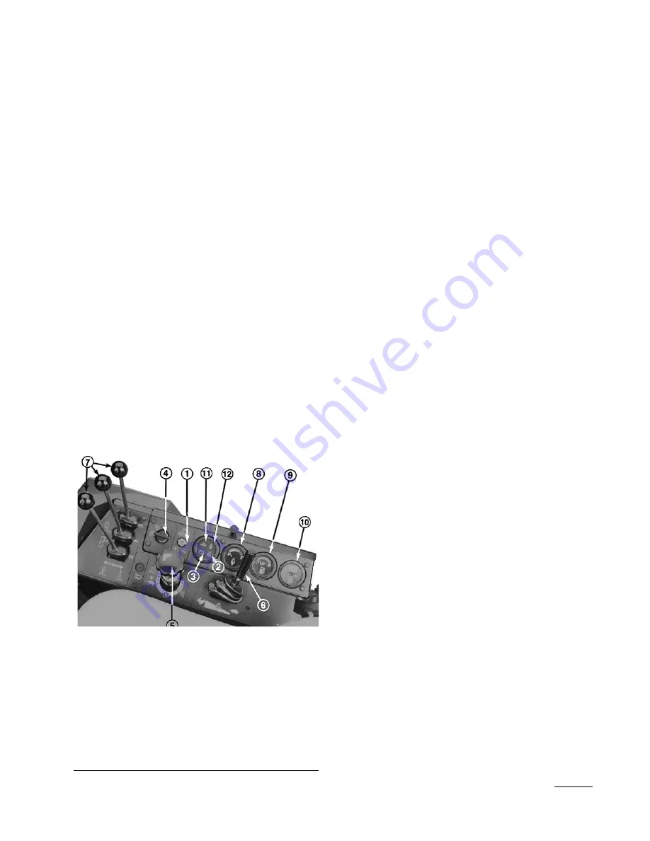
Figure 9
1.
Cutting unit engagement switch
2.
Glow plug indicator
3.
Charge indicator
4
Key Switch
5.
Reel speed control
6.
Throttle control
7.
Cutting unit lift controls
8.
Coolant temperature gauge
0.
Fuel gauge
10.
Hour meter
11.
Engine oil pressure warning light
12.
Engine coolant temperature warning light
Throttle Control (Fig 9)—Move the control forward
to increase engine speed, backward to decrease it.
Cutting Unit Lift Controls (Fig 9)—The two outside
levers raise and lower the two outside the cutting units.
The center lever raises and lowers the center cutting
unit. The engine must be running to lower the cutting
units. When the cutting units are lifted, the reels auto-
matically stop. To lower the cutting units just touch
levers momentarily. .
Coolant Temperature Gauge (Fig 9)—Shows tem-
perature of engine coolant.
Fuel Gauge (Fig. 9)—Shows amount of fuel in the
tank.
Hour Meter (Fig. 9)—Shows the total hours the
machine has been operated.
Engine Oil Pressure Warning Light (Fig 9)—
Indicates dangerously low engine oil pressure.
Engine Coolant Temperature Warning Light (Fig.
9—The red light illuminates and the engine stops
when the coolant temperature exceeds 110° C (230°
F.)
Seat (Fig. 10)—The seat adjusting lever on left side of
the seat allows a 10 cm (4-in) fore and aft adjustment.
The seat adjusting knob on the front of the seat,
adjusts the seat for the operator’s weight.
Traction Pedal (Fig. 11)—Controls forward and
reverse operation. Depress the top of the pedal to
move forward and the bottom to move backward.
Ground speed depends on how far the pedal is
depressed. For no-load, maximum ground speed, fully
depress the pedal while the throttle is in FAST. For
maximum power under load or when going uphill,
keep engine rpm high by having the throttle in FAST
and the traction pedal partially engaged. If engine rpm
begins to decrease due to load, gradually reduce the
traction pedal pressure until the engine speed is
increased.
Controls


