background image

WARNING

The blade is sharp; contacting the blade can result
in serious personal injury.

Wear gloves when servicing the blade.

1.

Disconnect the spark plug wire from the spark plug.
Refer to Preparing for Maintenance (page 13).

2.

Tip the machine onto its side, with the dipstick down.

3.

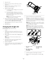
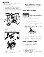
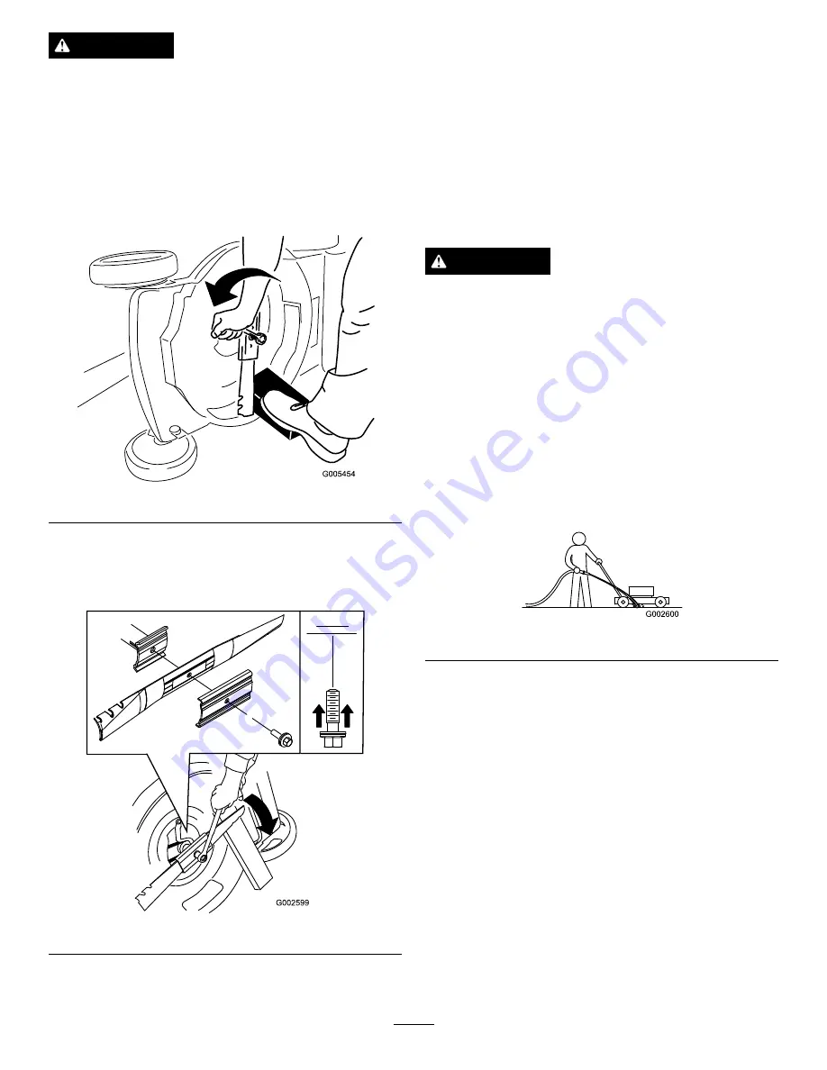
Use a block of wood to hold the blade steady
(Figure 39).

Figure 39

4.

Remove the blade, saving all mounting hardware
(Figure 39).

5.

Install the new blade (turn the blade bolt clockwise)
and all mounting hardware (Figure 40).

Figure 40

Important:

Position the curved ends of the blade

to point toward the machine housing.

6.

Use a torque wrench to tighten the blade bolt to
82 N-m (60 ft-lb).

Important:

A bolt torqued to 82 N-m (60 ft-lb) is

very tight. While holding the blade with a block
of wood, put your weight behind the ratchet or
wrench and tighten the bolt securely. This bolt is
very difficult to overtighten.

Cleaning the Machine

Service Interval:

Before each use or daily

WARNING

The machine may dislodge material from under the
machine housing.

Wear eye protection.

Stay in the operating position (behind the
handle).

Do not allow bystanders in the area.

1.

With the engine running on a flat paved surface, spray
a stream of water in front of the

right

rear wheel

(Figure 41).

Note:

The water will splash into the path of the blade,

cleaning out the clippings.

Figure 41

2.

When no more clippings come out, stop the water and
move the machine to a dry area.

3.

Run the engine for a few minutes to dry the housing
to prevent it from rusting.

Emptying the Fuel Tank

1.

Stop the engine and wait for it to cool down.

2.

Disconnect the wire from the spark plug.

3.

Remove the cap from the fuel tank.

4.

Use a hand pump to syphon the fuel into a clean
approved gasoline container.

5.

Connect the wire to the spark plug.

6.

Run the engine until it stops.

7.

Start the engine again to make sure that all the gasoline
is out of the carburetor.

17

Summary of Contents for Recycler 20952

Page 1: ...ecautions Figure 2 1 Safety alert symbol This manual uses 2 words to highlight information Important calls attention to special mechanical information and Note emphasizes general information worthy of special attention This product complies with all relevant European directives For details see the separate product specific Declaration of Conformity DOC sheet For models with stated engine horsepowe...

Page 2: ...w children or people unfamiliar with these instructions to use the mower Local regulations can restrict the age of the operator Keep in mind that the operator or user is responsible for accidents or hazards occurring to other people or their property Understand explanations for all pictograms used on the mower or in the instructions Gasoline WARNING Gasoline is highly flammable Take the following ...

Page 3: ...he machine Never store the machine with gasoline in the tank and inside a building where fumes can reach an open flame or spark Allow the engine to cool before storing in any enclosure To reduce the risk of fire keep the engine silencer battery compartment and gasoline storage area free of grass leaves or excessive grease Check grass catcher components and the discharge guard frequently and replac...

Page 4: ...ug wire before performing any maintenance on the machine 3 Thrown object hazard keep bystanders a safe distance from the machine 4 Cutting dismemberment hazard of hand or foot stay away from moving parts 5 Thrown object hazard keep deflector in place 110 7059 1 Read the Operator s Manual 4 Install the fuse 2 Remove the fuse box decal 5 Replace the fuse box cover 3 Remove the fuse box cover 6 Start...

Page 5: ...he handle knobs from the machine housing Figure 3 Important Route the cables to the outside of the handle as you install the handle 1 G020270 Figure 3 1 Handle knob 2 2 Move the handle to the operating position 3 Install and tighten the handle knobs that you removed in step 1 Figure 3 4 Move the upper handle to the desired position and tighten the upper handle knob firmly Figure 4 G020354 Figure 4...

Page 6: ... install the fuse 1 Remove the battery cover and the battery and locate the fuse holder Figure 8 Figure 8 1 Screw 3 Fuse holder 2 Battery cover 4 Battery 2 Insert the fuse from the loose parts bag into the fuse holder Figure 9 Figure 9 Note Your machine comes with a fuse in the owner s packet and another fuse in the battery box 3 Install the battery and the battery cover 4 Charging the Battery No ...

Page 7: ...10 Do not overfill Max fill 0 59 l 20 fl oz type SAE 30 or SAE 10W 30 detergent oil with an API service classification of SF SG SH SJ SL or higher 4 Install the dipstick securely Important Change the engine oil after the first 5 operating hours change it yearly thereafter Refer to Changing the Engine Oil page 14 Product Overview G020272 4 6 7 8 5 15 14 10 9 11 12 13 1 2 3 Figure 11 1 Blade control...

Page 8: ...line Fill the fuel tank with fresh unleaded regular gasoline from a major name brand service station Figure 12 Important To reduce starting problems add fuel stabilizer to the fuel all season mixing it with gasoline less than 30 days old G017304 Figure 12 Checking the Engine Oil Level Service Interval Before each use or daily Check the engine oil level 1 Remove the dipstick wipe it clean and fully...

Page 9: ...r the upper handle to a position comfortable for you Note You cannot raise the upper handle higher than the angle of the lower handle 1 Loosen the upper handle knob Figure 14 G020355 Figure 14 2 Move the upper handle to the desired position Figure 15 G020274 Figure 15 3 Tighten the upper handle knob firmly Figure 16 G020354 Figure 16 Starting the Engine 1 Hold the blade control bar Figure 17 again...

Page 10: ...engine stops within 3 seconds after releasing the blade control bar To stop the engine release the blade control bar Figure 22 Important When you release the blade control bar both the engine and blade should stop within 3 seconds If they do not stop properly stop using your machine immediately and contact an Authorized Service Dealer Figure 22 Recycling the Clippings Your machine comes from the f...

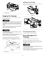
Page 11: ... the grass bag refer to Installing the Grass Bag page 11 and move the Recycling bagging lever to the bagging mode Figure 24 G020277 Figure 24 1 Bagging mode Installing the Grass Bag Raise and hold up the rear door Figure 25 install the bag Figure 26 and lower the rear door Figure 25 Figure 26 Removing the Grass Bag To remove the bag reverse the steps above Rear discharging the Clippings Use the re...

Page 12: ...only dry grass or leaves Wet grass and leaves tend to clump on the yard and can cause the machine to become clogged or the engine to stall WARNING Wet grass or leaves can cause serious injury if you slip and contact the blade Mow only in dry conditions Alternate the mowing direction This helps disperse the clippings over the lawn for even fertilization If the finished lawn appearance is unsatisfac...

Page 13: ...nual for any additional yearly maintenance procedures Preparing for Maintenance 1 Stop the engine and wait for all moving parts to stop 2 Disconnect the spark plug wire from the spark plug Figure 27 before performing any maintenance procedure G020278 1 Figure 27 1 Spark plug wire 3 After performing the maintenance procedure s connect the spark plug wire to the spark plug Important Before tipping t...

Page 14: ... a few minutes before changing the oil to warm it Note Warm oil flows better and carries more contaminants 3 Disconnect the wire from the spark plug Refer to Preparing for Maintenance page 13 4 Remove the dipstick 5 Tip the machine onto its side with the dipstick down to drain the used oil out through the oil fill tube Figure 29 G020279 Figure 29 6 Return the machine to the operating position 7 Sl...

Page 15: ...ording to national laws in the area The consumer has a critical role in returning waste electronic electrical equipment for recycling and disposal Recycling keeps these products out of the municipal waste stream The crossed out bin symbol is a reminder to follow these points Please contact your local authority or local dealer and ask for further details regarding the correct method of disposal Lub...

Page 16: ... how far the upper end of the cable jacket moves Figure 38 Figure 38 1 Cable mount 2 Cable jacket Note Moving the cable jacket upward decreases the ground speed moving the jacket downward increases the ground speed 5 Tighten the nut firmly 6 Start the machine and check the adjustment Note If the self propel drive is not properly adjusted repeat this procedure Replacing the Blade Service Interval Y...

Page 17: ...bolt is very difficult to overtighten Cleaning the Machine Service Interval Before each use or daily WARNING The machine may dislodge material from under the machine housing Wear eye protection Stay in the operating position behind the handle Do not allow bystanders in the area 1 With the engine running on a flat paved surface spray a stream of water in front of the right rear wheel Figure 41 Note...

Page 18: ...lding the Handle WARNING Folding or unfolding the handle improperly can damage the cables causing an unsafe operating condition Do not damage the cables when folding or unfolding the handle If a cable is damaged contact an Authorized Service Dealer 1 Loosen both handle knobs that attach the handle to the chassis until you can move the handle freely Figure 42 1 2 G020271 Figure 42 1 Handle knob 2 2...

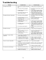
Page 19: ... hard or loses power 6 The fuel tank contains stale fuel 6 Drain and fill the fuel tank with fresh gasoline 1 The wire is not connected to the spark plug 1 Connect the wire to the spark plug 2 The air filter element is dirty and is restricting the air flow 2 Clean the air filter pre cleaner and or replace the paper air filter The engine runs rough 3 The spark plug is pitted fouled or incorrectly g...

Page 20: ...Notes 20 ...

Page 21: ...Notes 21 ...

Page 22: ...Notes 22 ...

Page 23: ...rmation Toro Collects Toro Warranty Company Toro respects your privacy In order to process your warranty claim and contact you in the event of a product recall we ask you to share certain personal information with us either directly or through your local Toro company or dealer The Toro warranty system is hosted on servers located within the United States where privacy law may not provide the same ...

Page 24: ...turer 5Whichever occurs first 6Lifetime Frame Warranty If the main frame consisting of the parts welded together to form the tractor structure that other components such as the engine are secured to cracks or breaks in normal use it will be repaired or replaced at Toro s option under warranty at no cost for parts and labor Frame failure due to misuse or abuse and failure or repair required due to ...

Reviews: