3
g017848
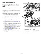
Figure 57
1.
Left cable adjustment
3.
Right cable adjustment
2.
Cable lock
7.
Check for proper tracking.
Note:
If the machine will not start after adjusting
the tracking, make sure proximity switch target aligns
with bolt attached to motion-control lever; refer to
Adjusting the Proximity Switch (page 41)
.
8.
Repeat the cable adjustment until the tracking is
correct.
9.
Check that the machine does not creep from neutral
with the park brakes disengaged.
Important:
Do not rotate the linkage too far, as this
may cause the machine to creep in neutral.
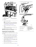
Adjusting the Proximity Switch
Use this procedure if the machine will not start after adjusting
the tracking.
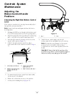
1.
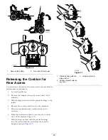
Ensure that the bolt attached to the motion-control
lever aligns with the proximity switch target (
).
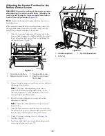
2.
If needed, loosen the bolts and adjust the proximity
switch until the target aligns with the bolt attached to
the motion-control lever (
).
3.
Check the distance of the bolt to the proximity switch;
it needs to be between 0.51 to 1.02 mm (0.02 to 0.04
inches) as shown in
4.
If adjustment is needed, loosen the jam nut and adjust
the bolt to the correct distance.
5.
Tighten the jam nut after adjusting the bolt (
).
6.
Test the safety-interlock system before operation.
G015609
1 6
2 3 4
4
2
5
6
Figure 58
1.
Proximity switch target
4.
Bolt attached to the
motion-control lever
2.
Proximity switch
5.
Distance between 0.51
to 1.02 mm (0.02 to 0.04
inches) is needed
3.
Bolts and nuts
6.
Jam nut
41
Summary of Contents for GrandStand 74574
Page 65: ...g026979 Electrical Schematic Rev A 65 ...
Page 66: ...Notes 66 ...
Page 67: ...Notes 67 ...

