background image

Electrical System
Maintenance

Electrical System Safety

Disconnect the battery before repairing the
machine. Disconnect the negative terminal first
and the positive last. Connect the positive terminal
first and the negative last.

Charge the battery in an open, well-ventilated
area, away from sparks and flames. Unplug the
charger before connecting or disconnecting the
battery. Wear protective clothing and use insulated
tools.

Battery acid is poisonous and can cause burns.
Avoid contact with skin, eyes, and clothing. Protect
your face, eyes, and clothing when working with a
battery.

Battery gases can explode. Keep cigarettes,
sparks, and flames away from the battery.

Servicing the Battery

Service Interval:

Every 75 hours—Check the battery

cable connections.

Every 75 hours—Clean the battery.

Always keep the battery clean and fully charged. Use
a paper towel to clean the battery case. If the battery
terminals are corroded, clean them with a solution of
4 parts water and 1 part baking soda. Apply a light
coating of grease to the battery terminals to reduce
corrosion.

Specifications:

12 V, 450 A (cold cranking)

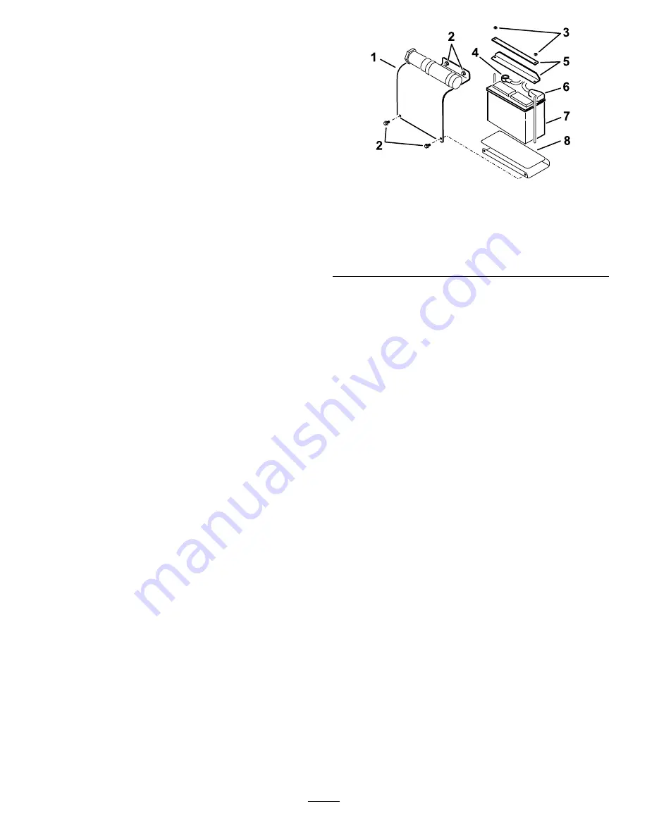
Removing the Battery

1.

Park the machine on a level surface, engage the
parking brake, and lower the loader arms.

2.

Shut off the engine and remove the key.

3.

Remove the battery cover (

Figure 35

)

g230939

Figure 35

1.

Battery cover

5.

Nut

2.

Bolt

6.

Positive battery cable

3.

Battery

7.

Negative battery cable

4.

Bars

8.

Battery pad

4.

Remove the nuts and bars securing the battery
(

Figure 35

).

5.

Disconnect the negative (black) cable to the
negative (-) battery post (

Figure 35

).

6.

Disconnect the positive (red) cable to the
positive (+) battery post (

Figure 35

).

7.

Lift the battery off the platform.

33


Summary of Contents for Dingo 320-D

Page 1: ...Form No 3430 249 Rev A 320 D Compact Tool Carrier Model No 22337CP Serial No 404340000 and Up Register at www Toro com Original Instructions EN 3430 249 A...

Page 2: ...designed to operate a wide variety of attachments each of which perform a specialized function Using this product for purposes other than its intended use could prove dangerous to you and bystanders...

Page 3: ...essing Internal Components 27 Lubrication 28 Greasing the Machine 28 Engine Maintenance 28 Engine Safety 28 Servicing the Air Cleaner 28 Servicing the Engine Oil 29 Fuel System Maintenance 31 Draining...

Page 4: ...the machine the heavy end Most other attachments make the front of the machine the heavy end Have the property or work area marked for buried lines and other objects and do not dig in marked areas Re...

Page 5: ...on explosive gases can cause blindness and other injuries 3 Caustic liquid chemical burn hazard 8 Battery acid can cause blindness or severe burns 4 Wear eye protection 9 Flush eyes immediately with w...

Page 6: ...4 Warning read the Operator s Manual decal108 4723 108 4723 1 Auxiliary hydraulics 3 Neutral off 2 Locked reverse detent 4 Forward decal114 9600 114 9600 1 Read the Operator s Manual decal120 0627 12...

Page 7: ...s Manual before performing maintenance 2 Warning remove the ignition key and lower the loader arms before leaving the machine 3 Cutting hazard of hand wait for moving parts to stop 4 Crushing dismembe...

Page 8: ...rd do not step off operator platform with load raised always operate with the heavy end of the machine pointed uphill carry loads low never jerk the controls use a steady even motion maximum load is 2...

Page 9: ...igure 3 g230938 Figure 3 1 Speed selector lever 3 Nut 2 Speed selector valve 2 Checking the Fluid Levels and Tire Pressure No Parts Required Procedure Before starting the engine for the first time che...

Page 10: ...ustment 2 Move the throttle to the FAST position 3 Using a tachometer and the throttle adjustment screw on the engine Figure 4 set the engine speed to 3 200 rpm maximum then tighten the jam nut on the...

Page 11: ...points 20 Radiator fill cap 3 Auxiliary hydraulic couplers 9 Operator platform removable counterweight not shown 15 Handle 21 Thigh support 4 Loader arms 10 Rear access cover open 16 Battery 22 Flow d...

Page 12: ...the attachment forward slowly push the attachment tilt lever forward To tilt the attachment rearward slowly pull the attachment tilt lever rearward Loader Arm Lever To lower the loader arms slowly pus...

Page 13: ...regular intervals for 6 hours Flow Divider Control The traction unit hydraulics i e the traction drive loader arms and attachment tilt work on a separate hydraulic circuit from the auxiliary hydrauli...

Page 14: ...Service Dealer for diagnostics and repair Oil Pressure Light This light is on for a few seconds whenever you start the engine If the oil pressure light is on while the engine is running the engine oi...

Page 15: ...untrained people to operate or service the machine Local regulations may restrict the age or require certified training of the operator The owner is responsible for training all operators and mechani...

Page 16: ...with low 500 ppm or ultra low 15 ppm sulfur content The minimum cetane rating should be 40 Purchase fuel in quantities that you can use within 180 days to ensure fuel freshness Use summer grade diese...

Page 17: ...Before starting the machine each day perform the Each Use Daily procedures listed in the Maintenance page 25 Important Check the hydraulic fluid level and bleed the fuel system before starting the en...

Page 18: ...and use caution when making turns and crossing roads and sidewalks Watch for traffic Stop the attachment when you are not working Stop the machine turn off the engine remove the key and inspect the m...

Page 19: ...gine may be started without waiting for the light to turn off Important Do not engage the starter for more than 10 seconds at a time If the engine fails to start wait 30 seconds for the starter to coo...

Page 20: ...late forward 4 Position the mount plate into the upper lip of the attachment receiver plate Figure 13 g003710 Figure 13 1 Mount plate 2 Receiver plate 5 Raise the loader arms while tilting back the mo...

Page 21: ...RAL position to relieve pressure at the hydraulic couplers 3 Remove the protective covers from the hydraulic connectors on the machine 4 Ensure that all foreign matter is cleaned from the hydraulic co...

Page 22: ...Do not exceed 4 8 km h 3 mph when towing 6 After repairing the machine close the tow valves and tighten the jam nuts Important Do not overtighten the tow valves 7 Replace the plugs Hauling the Machine...

Page 23: ...nnect the trailer brakes 3 Lower the ramp s 4 Lower the loader arms 5 Load the machine onto the trailer with the heavy end up the ramp carrying loads low Figure 17 If the machine has a full load beari...

Page 24: ...ng attachment e g trencher back it down the ramp If the machine has an empty load bearing attachment or no attachment drive it forward down the ramp g237905 Figure 19 1 Machine with full attachment or...

Page 25: ...amper with the safety devices Use only Toro approved attachments Attachments can change the stability and the operating characteristics of the machine You may void the warranty if you use the machine...

Page 26: ...y raised position 3 Shut off the engine and remove the key 4 Position a cylinder lock over each lift cylinder rod Figure 20 g005162 Figure 20 1 Cylinder lock 4 Clevis pin 2 Lift cylinder 5 Lift cylind...

Page 27: ...r the arms 3 Shut off the engine and remove the key 4 Release the 2 locking tabs Figure 22 top left tab illustrated g005943 Figure 22 1 Cover 2 Locking tab 5 Pull the cover off the machine 6 When fini...

Page 28: ...ting or overspeed the engine Keep your hands feet face clothing and other body parts away from the muffler and other hot surfaces Servicing the Air Cleaner Service Interval Every 200 hours Service the...

Page 29: ...H 4 CI 4 or higher Crankcase Capacity with filter 3 2 L 0 84 US gallons Viscosity See the table below g238048 Figure 27 Checking the Engine Oil Level 1 Park the machine on a level surface engage the p...

Page 30: ...wipe the filter adapter Figure 30 gasket surface g000653 Figure 30 1 Oil filter 3 Adapter 2 Gasket 9 Apply a thin coat of new oil to the rubber gasket on the replacement filter Figure 30 10 Install t...

Page 31: ...ttom of the fuel tank g005935 Figure 31 1 Fuel filter 2 Drain valve 5 Close the valve 6 Close the rear access cover Changing the Fuel Filter Service Interval Yearly Important Never install a dirty fil...

Page 32: ...drain pan 8 Open the vent plug and crank the engine until fuel comes out a steady stream 9 Close the vent plug 10 Close the rear access cover Draining the Fuel Tank 1 Park the machine on a level surfa...

Page 33: ...ble connections Every 75 hours Clean the battery Always keep the battery clean and fully charged Use a paper towel to clean the battery case If the battery terminals are corroded clean them with a sol...

Page 34: ...chine Removing the Battery page 33 4 Wash the entire case with a solution of baking soda and water 5 Rinse the battery with clear water 6 Coat the battery posts and cable connectors with Grafo 112X sk...

Page 35: ...radiator cap Use a rag when opening the radiator cap and open the cap slowly to allow steam to escape Cleaning the Radiator Screen Service Interval Before each use or daily Remove any buildup of grass...

Page 36: ...ealed Changing the Engine Coolant Service Interval Yearly Have an Authorized Service Dealer change the engine coolant yearly If you need to add engine coolant refer to Checking the Engine Coolant Leve...

Page 37: ...wing fluids in the hydraulic system Toro Premium Transmission Hydraulic Tractor Fluid refer to your Authorized Service Dealer for more information Toro PX Extended Life Hydraulic Fluid refer to your A...

Page 38: ...After the first 8 hours Every 400 hours Important Do not substitute an automotive oil filter otherwise severe hydraulic system damage may result 1 Park the machine on a level surface remove any attac...

Page 39: ...nd lower the loader arms Cleaning Removing Debris Service Interval Before each use or daily Important Operating the engine with blocked screens and or cooling shrouds removed will result in engine dam...

Page 40: ...ge 31 7 Torque the wheel lug nuts to 68 N m 50 ft lb 8 Check the hydraulic fluid level refer to Checking the Hydraulic Fluid Level page 38 9 Check the tire pressure refer to Checking the Tire Pressure...

Page 41: ...line 6 There is air in the fuel 6 Bleed the nozzles and check for air leaks at the fuel hose connections and fittings between the fuel tank and engine 7 The glow plugs are inoperative 7 Check the fus...

Page 42: ...ir in the fuel 3 Bleed the nozzles and check for air leaks at the fuel hose connections and fittings between the fuel tank and engine 4 The injection nozzles are damaged 4 Contact your Authorized Serv...

Page 43: ...fuel system 4 Drain and flush the fuel system add fresh fuel 5 The engine is overheating 5 Refer to The engine overheats 6 The spark arrestor screen is clogged 6 Clean or replace the spark arrestor sc...

Page 44: ...ompression 6 Contact your Authorized Service Dealer 1 The parking brake is engaged 1 Disengage the parking brake 2 The hydraulic fluid level is low 2 Add hydraulic fluid to the reservoir 3 The hydraul...

Page 45: ...Schematics g030503 Electrical Schematic Rev C 45...

Page 46: ...g029270 Hydraulic Schematic Rev B 46...

Page 47: ...these activities We will not sell your personal information to any other company We reserve the right to disclose personal information in order to comply with applicable laws and with requests by the...

Page 48: ...to restaurants grocery stores hotels schools and hospitals and on a wide variety of products Additionally some online and mail order retailers provide Prop 65 warnings on their websites or in catalogs...

Reviews: