background image

Installation

4

Remove Carrier Frame

1.

Remove hairpin cotters and clevis pins from
mower hanger brackets and remove mower from
carrier frame (Fig. 1).

1

m-3531

3

2

Figure 1

1.

Mower Hanger Bracket

2.

Clevis Pin

3.

Hairpin Cotter

Install Castor Wheels

1.

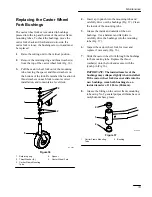
Place spacer and (2) thrust washers on shaft and
slide the castor wheel into the mounting tube
(Fig. 2).

2.

Place (2) thrust washers on top of the fork and
secure with retaining ring (Fig. 2).

Note:

The location of the thrust washers on
each fork may need adjustment to
maintain a level deck.

3.

Grease the fitting on the carrier frame mounting
tube using No. 2 general purpose lithium base or
molybdenum base grease, refer to: Greasing and
Lubrication.

4.

Set the castor wheel tire pressure to 50 psi
(345 kPa).

m-3531

4

2

2

1

3

6

5

Figure 2

1.

Retaining  ring

2.

Thrust Washer (4)

3.

Spacer

4.

Carrier Frame Mounting
Tube

5.

Grease fitting

6.

Castor Wheel Fork

Summary of Contents for 78477

Page 1: ...ly It contains information about your safety and the safety of others Also become familiar with the controls and their proper use before you operate the product FORM NO 3321 443 Z Master 48 Recycler for OUT FRONT Z TRACTION UNIT Model No 78477 891696 Up ...

Page 2: ...Serial No The warning system in this manual identifies potential hazards and has special safety messages that help you and others avoid personal injury even death DANGER WARNING and CAUTION are signal words used to identify the level of hazard However regardless of the hazard be extremely careful DANGER signals an extreme hazard that will cause serious injury or death if the recommended precaution...

Page 3: ... Power Take Off PTO 10 Adjusting Height of Cut 11 Adjusting Rollers 11 Tilting the Mower 12 Page Maintenance 13 Service Interval Chart 13 Cutting Blades 13 Correcting Cutting Unit Mismatch 16 Setting the Front to Rear Pitch 17 Setting the Side to Side Leveling 17 Greasing and Lubrication 18 Replacing the Castor Wheel Fork Bushings 19 Servicing the Castor Wheels and Bearings 20 Replacing Push Arm B...
Page 4: ...Safety 2 Safety and Instruction Decals Safety decals and instructions are easily visible to the operator and are located near any area of potential danger Replace any decal that is damaged or lost ...

Page 5: ...Install push arms to carrier frame Spring Assembly Shoulder Bolt 3 8 16 x 7 8 22 mm Locknut 3 8 16 2 2 2 Install springs to carrier frame Shoulder Bolt 3 8 16 x 7 8 22 mm Locknut 3 8 16 Bolt 3 8 16 x 1 5 8 41 5 mm Locknut 3 8 16 2 2 2 2 Install mower to traction unit Save when removing PTO drive shaft Shoulder bolt 5 16 18 x 7 16 11 mm Flange nut 5 16 18 1 1 Secure power take off PTO cover Operato...

Page 6: ...e Fig 2 2 Place 2 thrust washers on top of the fork and secure with retaining ring Fig 2 Note The location of the thrust washers on each fork may need adjustment to maintain a level deck 3 Grease the fitting on the carrier frame mounting tube using No 2 general purpose lithium base or molybdenum base grease refer to Greasing and Lubrication 4 Set the castor wheel tire pressure to 50 psi 345 kPa m ...

Page 7: ... 3 8 x 7 8 23 mm shoulder bolt and 3 8 locknut Fig 4 1 m 3209 3 2 Figure 4 1 Spring Assembly 2 Shoulder Bolt 3 8 x 7 8 22 mm 3 Locknut 3 8 Installing Mower 1 Position carrier frame in front of traction unit and place push arms into clevises Fig 5 2 Retain push arms with pivot pin assemblies aligned with flat against frame and secure with hairpin cotters Fig 5 Note Pivot pin assemblies and hairpin ...

Page 8: ... 2 Shoulder Bolt 3 8 x 7 8 22 mm 3 Locknut 3 8 5 Roll mower in front of traction unit 6 Rotate PTO drive shaft so holes in universal joint align with hole in gearbox shaft and slide together Fig 7 7 Drive roll pin through hole in universal joint to secure PTO drive shaft to gearbox shaft Fig 7 Note Drive shaft and roll pin are part of traction unit 1 2 4 m 3376 3 Figure 7 1 PTO Driveshaft 2 Univer...

Page 9: ...ure 8 1 Mower Hanger Bracket 2 Clevis Pin 3 Hairpin Cotter 11 Secure PTO cover down with 5 16 18 x 7 8 11 mm shoulder bolt and 5 16 flange nut Fig 9 2 m 3718 3 1 Figure 9 1 PTO cover 2 Shoulder bolt 5 16 18 x 7 8 11 mm 3 Flange nut 5 16 Removing the Mower 1 Remove 5 16 18 x 7 8 11 mm shoulder bolt and 5 16 flange nut holding PTO cover down Fig 9 2 Drive roll pin through hole in universal joint to ...

Page 10: ...e Mower 6 Remove hairpin cotters and clevis pins from mower hanger brackets and remove mower from carrier frame Fig 12 1 m 3532 3 2 Figure 12 1 Mower Hanger Bracket 2 Clevis Pin 3 Hairpin Cotter 7 Raise the carrier frame and roll the mower away from traction unit 8 Lower carrier frame and remove hairpin cotters and pivot pin assemblies securing push arms to traction unit clevises Fig 13 Note Save ...

Page 11: ...8 16 locknuts from universal joint and slide the driveshaft off gearbox shaft Fig 14 Note Save all hardware for use when installing mower 1 2 4 m 3198 3 5 Figure 14 1 PTO Driveshaft 2 Universal Joint 3 Gearbox shaft 4 Bolt 3 8 16 x 1 5 8 41 5 MM 5 Locknut 3 8 16 ...

Page 12: ...the traction control levers and place in neutral Fig 15 2 Release the parking brake Fig 15 m 3939 3 2 1 Figure 15 1 Traction control lever 2 Parking brake 3 PTO Switch 3 To engage lift cover and move the PTO switch to the ON position Fig 16 Disengaging the PTO 1 Closing the cover moves the PTO switch to the OFF position Fig 16 m 2721 2 1 Figure 16 1 PTO Off 2 PTO On ...

Page 13: ...in the same hole location for a level cut 1 m 3532 3 2 Figure 17 1 Mower Hanger Bracket 2 Clevis Pin 3 Hairpin Cotter Adjusting Rollers The rollers are preset for heights of cut above 2 51 mm If the height of cut is set to the 1 or 1 1 2 25 or 39 mm the rollers must be adjusted to the upper hole location 1 After adjusting height of cut tilt mower to adjust rollers refer to Tilting Mower 2 Remove t...

Page 14: ...rake 2 PTO cover 3 Latch pin 4 Notch open 4 Standing in front of the mower lift up and push rearward on front to raise mower Fig 20 Raise mower until it contacts stops and latch pins snap into locked position m 3375 1 Figure 20 1 Mower up To Lower Mower 1 Pull out latch pins and rotate into notch to hold in the open position Fig 19 Standing in front of the mower pull forward on front and lower mow...

Page 15: ... replacement you may want to keep extra blades on hand POTENTIAL HAZARD A blade that is worn or damaged could break apart and pieces could be thrown at bystanders or at you as you use the mower WHAT CAN HAPPEN Pieces of blade that may be thrown could seriously injure or kill you or bystanders HOW TO AVOID THE HAZARD Periodically inspect the blade for wear and damage Immediately install a new blade...

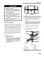
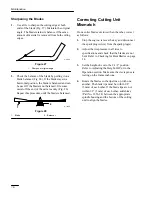
Page 16: ...t Forming Checking for Bent Blades 1 Rotate the blades until the ends face forward and backward Fig 23 Measure from a level surface to the cutting edge of the blades Fig 24 Note this dimension 2 Rotate the opposite ends of the blades forward Measure from a level surface to the cutting edge of the blades at the same position as in step 1 above The difference between the dimensions obtained in steps...

Page 17: ...lade end using a rag or thickly padded glove Remove the retainer bolt with its washer and spacer and the blade bolts and locknuts from the blade retainer Fig 26 Installing the Blades IMPORTANT The blades are different for each side and rotate in opposite directions forcing clippings to the center rear of the mower Align cutting edges properly when installing Fig 25 Front m 3372 1 1 1 Figure 25 1 C...

Page 18: ...ade 2 Balancer Correcting Cutting Unit Mismatch If one cutter blade cuts lower than the other correct as follows 1 Stop the engine remove the key and disconnect the spark plug wire s from the spark plug s 2 Adjust the tire pressure in all tires to specifications and check that the blades are not bent Refer to Checking for Bent Blades on page 14 3 Set the height of cut to the 2 1 2 position Refer t...

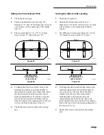
Page 19: ... the top to lower the front of the mower Fig 36 5 Check the side to side leveling of the cutting unit Setting the Side to Side Leveling 1 Check the tire pressure 2 Position the blades side to side Fig 31 Measure at A and B locations Fig 31 from a level surface to the cutting edge of blades Fig 32 3 The difference between measurements A and B should be no more than 1 4 6 mm Front m 3372 A B Figure ...

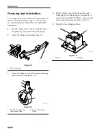
Page 20: ...he fittings on push arms Fig 33 1 m 3936 Figure 33 1 Push arm bearing 3 Grease the fittings on the carrier frame mounting tubes and castor wheels Fig 34 m 3281 1 2 Figure 34 1 Carrier Frame Mounting Tube Grease Fitting 2 Castor Wheel Grease Fitting 4 Remove plug on the side of the gearbox and check the level of lubrication in the gearbox If level is low add SAE EP 80 90 wt gear oil until level is ...

Page 21: ...asher 4 3 Carrier Frame Mounting Tube 4 Spacer 5 Castor Wheel Fork 4 Insert a pin punch into the mounting tube and carefully drive out the bushings Fig 37 Clean the inside of the mounting tube 5 Grease the inside and outside of the new bushings Use a hammer and flat plate to carefully drive the bushings into the mounting tube Fig 37 6 Inspect the castor wheel fork for wear and replace if necessary...

Page 22: ... wheel hub and clean any grease and dirt from the wheel hub Fig 38 4 Inspect the roller bearing bushings spanner bushing and inside of the wheel hub for wear Replace any defective or worn parts Fig 38 5 To assemble place one 1 bushing into the wheel hub Grease the roller bearing and spanner bushing and slide them into the wheel hub Place the second bushing into the wheel hub Fig 38 6 Install the c...

Page 23: ...retaining ring and flat washer securing the push arm to the mower Fig 39 1 m 3936 2 3 4 Figure 39 1 Pin 2 Push arm 3 Flat washer 1 1 2 38 mm 4 Retaining ring 4 Insert a pin punch into the push arm and carefully drive out the bushings Fig 40 Clean the inside of the push arm 5 Use a hammer and flat plate to carefully drive new bushings into the end of push arm Fig 40 6 Place push arm onto carrier fr...

Page 24: ...rden hose 3 Check the condition of the blades Refer to Cutting Blades on page 13 4 Check and tighten all bolts nuts and screws Repair or replace any damaged or defective parts 5 Paint all scratched or bare metal surfaces Paint is available from your Authorized Service Dealer 6 Store the machine in a clean dry garage or storage area Cover the machine to protect it and keep it clean ...

Page 25: ...lace gears 7 Blade spindle bent 7 Replace spindle 8 Universal joint worn 8 Replace universal joint Uneven cutting height 1 Blade s not sharp 1 Sharpen blade s 2 Cutting blade s is are bent 2 Install new cutting blade s 3 Mower is not level 3 Level mower from side to side and front to rear 4 Underside of mower is dirty 4 Clean the underside of the mower 5 Tire pressure is incorrect 5 Adjust tire pr...

Page 26: ......

Page 27: ......

Page 28: ......

Reviews: